Super Star 2400 User manual

Operation Manual
3600 Channels 5-Mode
AM/FM/USB/LSB/CW
Mobile Transceiver

General Description
The Super star 2400 is a combination transmitter-receiver designed primarily
for mobile Use. It employs the very latest technology to provide 240 cha-
nnels + 480 channels (+/-5KHz) if operation by means of digital frequency
synthesis with PLL (phase-locked-loop) circuitry. The use of PLL assures a
precise on-frequency operation on every channel in both transmit and rec-
eive mode. The Super Star 2400 also includes many other features which
will provide greater operating convenience and assure optimum communi-
cations under a wide range of conditions.
Operable on 240 channels divided into six groups of 40 channels.
3-way RF Gain switch.
Full noise reduction features - ANL and noise blanker.
5 modes of operation - CW, LSB, USB, AM, or FM - selectable with a rotary
switch.
Provision of PA.
Concentrically mounted Fine and Coarse controls to fine tune to any trans-
missions or operate in inter-channel frequencies.
Tone switch to select receive tonal quality in 2-way.
RF power output switchable in 3-way for required communication range.
TX lamp that indicates you are on-the-air.
External speaker jack for an extra sound source.
The transceiver is ready for connection to a 13.8 Volt DC only negative
ground system.
A high-sensitivity dynamic microphone equipped.
CAUTION
FOR REPLACEMENT OF THE
FUSE IN DC POWER CABLE,
PLEASE BE SURE TO USE
3,5A FUSE.
2

Specifications
General
Frequency composition. PLL synthesizer
Frequency range. A 26.065 to 26.505 MHz
B 26.515 to 26.955 MHz
C 26.965 to 27.405 MHz
D 27.415 to 27.855 MHz
E 27.865 to 28.305 MHz
F 28.315 to 28.755 MHz
Channels. Total 3600: 240 5 MODE
240(+5 KHz) 5 MODE
240(- 5 KHz) 5 MODE
Frequency space. 10 to 20 KHz
Emission. AM/FM/USB/LSB/CW
Power source. 13.8 V DC (Only negative ground)
Receiver
Sensitivity. AM 1 micro-V @ 10 dB S/N
FM 1 micro-V @ 20 dB S/N
SSB/CW 0.5 micro-V @ 10 dB S/N
Selectivity. 60 dB
Audio Output. 2 W @ 8 Ohm
Fine Tune range. 800 Hz
Coarse Tune range.
Frequency. AM/FM 10.685 MHz/455 KHz
SSB/CW 10.695 MHz
Transmitter
RF power output. High Mid Low
SSB/CW (p-p) 12W 8W 2W
AM 7.5W 4W 1W
FM 10W 4W 1W
SSB generation. Double-balanced modulator with crystal
latice filter
Coarse Tune range. 5 khz
3

Operating Controls and Features
(1) Off/Volume Control
Varies the sound output from the speaker. Also incorporates an on-off switch
at the extremely counterclockwise position.
(2) Band Selector
Selects a group of 40 channels in six positions -A, B, C, D, E, or F(240 in all).
(3) Squelch Control
Used to eliminate any annoying background noise when no signals are present.
The degree of sensitivity to incoming signals is adjustable. When the Squelch
control is rotated to the fully clockwise position, it provides maximum squelch;
in the fully counterclockwise position, it provides minimum squelch.
(4) Mode Selector
Selects the mode of reception and transmission - CW (continuant wave), LSB
(lower side band), USB (upper side band), AM (amplitude modulation), or FM
(frequency modulation).
4
1112

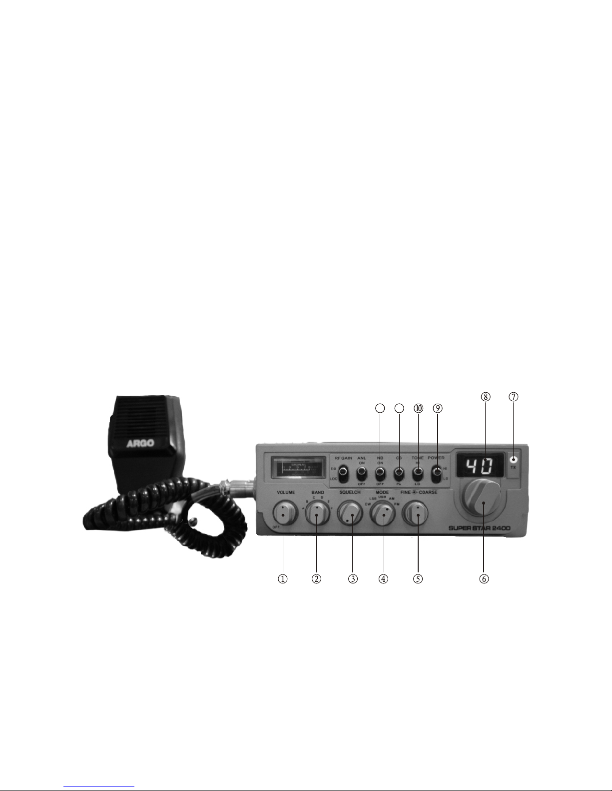
(5) Fine/Coarse Control
This is concentrically located control that permits individual adjustment of
receiving and/or transmitting frequencies.
Fine (inner knob). Provides fine tuning of the receiver section. On regular
AM and FM reception, this will permit adjustment to off-frequency transmis-
sions. In the SSB( either upper side band or lower side band) mode, this is
used as a voice clarifier to adjust for clearer voice reception. This control
will not affect the transmitter frequency.
Coarse Tune (outer knob). This control operates in the same manner as
the Fine knob except it provides adjust of both receive and transmit frequ-
encies.
(6) Channel selector.
A 40-detent rotary switch to select any of 240 channels in conjunction with
the band Selector switch.
Window above this switch indicates the channelss selected using an LED
(Light-emitting-diode) digital readout.
(7) TX indicator
Lights up when transmitting.
(8) Channel indicator
A digital LED display to show channel selected.
Turned off when operating PA.
(9) Power Selector
Enables you to select the RF power output of the transceiver in 3 ways:
High. In this position the transceiver produces full rated RF power for max-
imum communication range.
Middle. In this position, the RF power is medium level.
Low. In this position, the minimum RF power output is obtained, may be
used or short range communication.
Note. The RF power output level (W) which each position provides is depe-
ndent on the mode of operation. See Specifications section for specific RF
power output.
(10) Tone Switch
Changes tonal quality in receiving in 2 ways:
High. High tones in the sound output are emphasized.
Low. Low tones in the sound output are emphasized.
(11) CB-PA switch
When set to PA (lever down) position, the transceiver acts as a public add-
ress amplifier. Before operating PA, you must first connect an external PA
speaker (8 Ohm, More than 2 W) to the PA Speaker jack on the unit rear
panel.
5

(12) NB switch
Activates the noise blanker circuit which is effective in reduction of impulse
type noise (ignition noise, etc.).
(13) ANL switch
Activates the automatic noise limiter in the audio. The ANL will be effective
in reduction of atmospheric (discharge) interference.
(14) RF Gain switch
Selects RF Gain (receiver sensitivity) of the transceiver in 3 ways:
DX. In this position. The receiver section provides maximum sensitivity so
that it can pick up even weak signals.
Normally this switch should be placed in this position.
Mid. In this position. The receiver sensitivity is medium, and may be used
when you desire to pick only strong or fairly strong signals.
Local. In this position, the receiver sensitivity is minimum, and the receiver
will pick up only the strong signals. May be used when receiving strong
(close) signals which are causing overload in receiving sound.
(15) Meter
Serves to dual purpose
When receiving, this meter gives the relative strength of incoming signals
in `s`units. When transmitting, this gives RF power output in lower scale.
(16) Microphone jack
Accepts plug from the microphone supplied. The jack has a locating key in-
side and allows the plug inserted in only one way. Do not force the plug but
align key way properly onto the jack.
(17) Microphone
Supplied With transmit pushbar (PTT) mounted at the left side.
6
13
14
15
16
17

Rear panel Connection
(1) Antenna
Accepts a PL-259 type coaxial connector from the antenna lead-in cable.
(2) CW Key jack
Accepts a 3.5 mm 2-conductor phone plug to connect a CW key.
(3) External Speaker jack
Used to connect an external speaker (8 Ohm 4W) as an extra sound source.
Insertion of the plug from a speaker will silence the internal speaker auto-
matically.
(4) PA Speaker jack
Used to connect a PA speaker (8 Ohm 4W) for PA operation.
Before operating PA you must first connect a PA speaker to this jack.
(5) 13.8V DC jack
13.8 V DC power for the transceiver supplied through this socket (using DC
power cable supplied).
7
ANT
CW EXT SP PA 13.8V DC

Mobil Installation
Before installing the transceiver in a car, truck, boat, etc., Be sure to choose
a location which is convenient to the operating controls, and will not inter-
fere with the normal functions of the driver. The transceiver may be mounted
to the underside of the instrument panel or deshboard of a car, truck, ect.,
By means of the special bracket that is supplied with the transceiver.
Power Connection
The transceiver is designed to operate from a battery source of 13.8 Volt DC,
in vehicles only negative ground system. The fused DC power cable supplied
is used to make the necessary power connection to the transceiver. The red
[fused] lead is connected to the positive [+] side of the electrical system in
the vehicle, and the black lead is connected to the negative [-] side of the
system.
Antenna Connection
RG-58/u cable is generally used to connect the CB antenna to the transceiver.
The cable should be terminated with a PL-259 connector for connection to
the antenna input on the transceiver.
12V Battery
Negative (-) Terminal
12V Battery
Negative (+) Terminal
Fuse
[3.5 Amp]
To DC power socket
on the transceiver
BLACK
RED
8

Channel Selection
The transceiver is capable of operation on 240 channels which are divided
into 6 groups of 40 channels A, B, C, D, E and F. These groups are selected
with the Band Selector switch as the following.
Band switch
Position Frequency Range
A 26.065 to 26.505 MHz
B 26.515 to 26.955 MHz
C 26.965 to 27.405 MHz
D 27.415 to 27.855 MHz
E 27.865 to 28.305 MHz
F 28.315 to 28.755 MHz
After the band to which the channel you desire to operate belongs is selec-
ted, rotate the Channel selector to find the channel. Rotating the channel
selector clockwise or counterclockwise by 1 detent will tune the transceiver
10 Khz upscale or downscale. I.e. If you desire to operate on 27.405 MHz
first set the Band selector switch to `c`, then turn the channel selector to
the position at which the channel readout shows `40`
Operation
(1) Turn the Volume control clockwise to apply power to the transceiver.
The S-RF meter should be illuminated.
(2) Rotate the Squelch control counterclockwise fully.
(3) Set the CB-PA switch to CB position. Now background noise or transmi-
ssion should be heard.
(4) Select the mode of reception AM, SSB, FM, or CW.
(5) Set the RF Gain switch to DX position.
(6) Select the channel desired.
(7) To transmit, depress the transmit switch on microphone; to receive, re-
lease the switch.
RF Gain Switch Adjustment
Normally, this control should be set to DX position to provide maximum re-
ceiver sensitivity for long range reception. However, when communicating
with a nearby station, you may find that the strong signal from this station
may cause overloading of your receiver. In such a case, you can use this
switch to reduce the receiver sensitivity and thus prevent any overloading
and distortion that may occur as a result of the extremely strong incoming
signals. First set the switch to Mid position and if this position will not pro-
vide a sufficient reduction of overloading condition, set to Local position.
9

Fine Control 0 peation
This control provides fine tuning of the receiver by 0.8 Khz. On regular
AM or FM reception, this will permit slight adjustment of your tuning in ca-
ses where the received signal is slightly off-frequency. For SSB reception,
this control is used as a voice clarifier by turning it for clearest, most i1ntel-
ligible voice.
Coarse Tune Control Operation
This Control acts like a VFO (variable frequency oscillator) allowing inter-
channel reception and transmission. This shifts the assigned center frque-
ncy of the channel 5 KHz up (when rotated clockwise fully) or down (when
rotated counterclockwise fully). In the center position, the receiving and
transmitting frequency is normal (as listed in the Frequency/Channel Chart).
Stand-By Pee
Special provision has been made to your transceiver to give your partner a
sign by beep-tone to tell you are turning to receive. In each time you rele-
ase the push-to-talk button on the microphone, the beep tone is automat-
ically transmitted.
CW Operation
(1) Set the Mode selector to CW position.
(2) Connect a CW key to the CW key jack on the rear panel.
(3) To transmit with Morse codes, simply operate the key.
Note. To transmit CW, you may not depress the transmit switch (PTT) on
the microphone.
Morse Codes
A ( )
B ( )
C ( )
D ( )
E ( )
F ( )
G ( )
H ( )
I ( )
J ( )
K ( )
L ( )
M ( )
N ( )
O ( )
P ( )
Q ( )
R ( )
S ( )
T ( )
U ( )
V ( )
W ( )
X ( )
Y ( )
Z ( )
1 ( )
2 ( )
3 ( )
4 ( )
5 ( )
6 ( )
7 ( )
8 ( )
9 ( )
0 ( )
10

Frequency/Channel Chart
A-Band B-Band C-Band D-Band E-Band F-Band
Channel Frequency
Channel Frequency Channel Frequency Channel Frequency Channel Frequency Channel Frequency
1 26,065
2 26,075
3 26,085
4 26,105
5 26,115
6 26,125
7 26,135
8 26,155
9 26,165
10 26,175
11 26,185
12 26,205
13 26,215
14 26,225
15 26,235
16 26,255
17 26,265
18 26,275
19 26,285
20 26,305
21 26,315
22 26,325
23 26,355
24 26,335
25 26,345
26 26,365
27 26,375
28 26,385
29 26,395
30 26,405
31 26,415
32 26,425
33 26,435
34 26,445
35 26,455
36 26,465
37 26,475
38 26,485
39 26,795
40 26,505
1 26,515
2 26,525
3 26,535
4 26,555
5 26,565
6 26,575
7 26,585
8 26,605
9 26,615
10 26,625
11 26,635
12 26,655
13 26,665
14 26,675
15 26,685
16 26,705
17 26,715
18 26,725
19 26,735
20 26,755
21 26,765
22 26,775
23 26,805
24 26,785
25 26,795
26 26,815
27 26,825
28 26,835
29 26,845
30 26,855
31 26,865
32 26,875
33 26,885
34 26,895
35 26,905
36 26,915
37 26,925
38 26,935
39 26,945
40 26,955
1 26,965
2 26,975
3 27,985
4 27,005
5 27,015
6 27,025
7 27,035
8 27,055
9 27,065
10 27,075
11 27,085
12 27,105
13 27,115
14 27,125
15 27,135
16 27,155
17 27,165
18 27,175
19 27,185
20 27,205
21 27,215
22 27v225
23 27,255
24 27,235
25 27,245
26 27,265
27 27,275
28 27,285
29 27,295
30 27,305
31 27,315
32 27,325
33 27,335
34 27,345
35 27,355
36 27v365
37 27,475
38 27,385
39 27,395
40 27,405
1 27,415
2 27,425
3 27,435
4 27,455
5 27,465
6 27,475
7 27,485
8 27,505
9 27,515
10 27,525
11 27,535
12 27,555
13 27,565
14 27,575
15 27,585
16 27,605
17 27,615
18 27,625
19 27,635
20 27,655
21 27,665
22 27,675
23 27,705
24 27,685
25 27,695
26 27,715
27 27,725
28 27,735
29 27,745
30 27,755
31 27,765
32 27,775
33 27,785
34 27,795
35 27,805
36 27,815
37 27,825
38 27,835
39 27,845
40 27,855
1 27,865
2 27,875
3 27,885
4 27,905
5 27,915
6 27,925
7 27,935
8 27,955
9 27,965
10 27,975
11 27,985
12 28,005
13 28,015
14 28,025
15 28,035
16 28,055
17 28,065
18 28,075
19 28,085
20 28,105
21 28,115
22 28,125
23 28,155
24 28,135
25 28,145
26 28,165
27 28,175
28 28,185
29 28,195
30 28,205
31 28,215
32 28,225
33 28,235
34 28,245
35 28,255
36 28,265
37 28,275
38 28,285
39 28,295
40 28,305
1 28,315
2 28,325
3 28,335
4 28,355
5 28,365
6 28,375
7 28,385
8 28,405
9 28,415
10 28,425
11 28,435
12 28,455
13 28,465
14 28,475
15 28,485
16 28,505
17 28,515
18 28,525
19 28,535
20 28,555
21 28,565
22 28,575
23 28,605
24 28,585
25 28,595
26 28,615
27 28,625
28 28,635
29 28,645
30 28,655
31 28,665
32 28,675
33 28,685
34 28,695
35 28,705
36 28,715
37 28,725
38 28,735
39 28,745
40 28,755
M
HzM
HzM
HzM
HzM
HzM
Hz

Other manuals for 2400
1
Table of contents
Other Super Star Transceiver manuals

Super Star
Super Star 120 User manual

Super Star
Super Star SS-3900EFT User manual

Super Star
Super Star 360 User manual

Super Star
Super Star SS3 User manual

Super Star
Super Star 120FM User manual

Super Star
Super Star 3900 User manual

Super Star
Super Star 3900 OLED User manual

Super Star
Super Star SS-158EDX User manual

Super Star
Super Star 3900 User manual

Super Star
Super Star 3 User manual