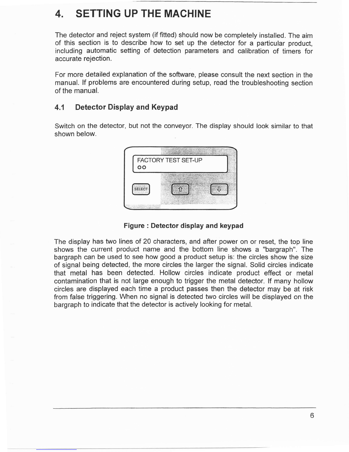
LOCK Inspection Sytems LTD MET 30 Plus User manual

N"t3'{{i?
MET
30+
MetalDetectors
Operating
Manual
INSPECTION SYSTEMS LTD

H3I$1
Lock
Inspection
Systems
MET
30+
Operatirg
Manual
Software
Version
1.xx
O2001
LOCKInspection
Systems
Ltd
Lock
House
Neville
Street
Oldham
Lancs
OL96LF
Tel
0161
6240333
Fax
0161
524
5181 REF:Q875-0019-issue
3

MET30+ Operating
Manual Metal
Detectors
CONTENTS
1. GENERAL
2. HEALTH
AND
SAFETY
2.1 Health
and
Safety
atWorketc.
Act
3. INTRODUCTION
4. SETTING
UP
THE
MACHINE
4.1 Deterctor
Display
and
Keypad
4.2 Initial Test
4.3 Product
Setup
4,4 TimerSetup
5. USING
THESOFTWARE
5.1 Power
up
5.2 Security
Codes
5.3 Operator
Menu
5.4 Supervisor
Menu
5.5 Engineers
Menu
6. OPERATION
CHART
7. TROUBLESHOOTING
GUIDE
7.1 FalseTriggering/PoorSensitivity
7.2 Fails
todetect
test
sample
7.3 Detects
sample
anddoesnot
falsetrigger
7.4 Detectssamplebutfalsetriggers
8. SAMPLE
TEST
8.1 Operation
8.2 Recommended
actiononfailing
test
8.3 Engineering
setup
8.4 Sample
test
flowchart
9. PRINTER
9.1 PrintModes
9.2 Reports
9.3 Engineering
SetuP
9.4 Printer
CableDiagrams
4
4
4
5
6
6
7
7
9
12
12
15
16
17
.,,
28
29
29
29
29
29
30
30
31
31
33
34
35
39
4l
43

10.
GLOSSARY
10.I Aperture
10.2 Bargraph
f0.3 Factory
Test
Setup
10.4 FaheTriggering
10.5 Metal-Free
Zone
70.6 Noise
10.7 ProductEffect
10.8 product
Guide
f0.9 Sensitivity
10.10 Skid
ptate
10.I1 Systemchek
10.12 Test
Sample
10.t3 Trigger
44
44
44
44
44
44
44
45
45
45
45
45
45
45
3


1. GENERAL
The
instructions
given
in
this
manual
have
been
written
clearly
and
briefly
toenable
an easy understanding
of the actions
necessary
to install
and operate
this
equipment.
lnorder
to ensuretrouble-free
andreliable
serviceit isstrongly
recommended
that
operatorsof the equipmentareprovided
with
thismanual
in order
to familiarise
themselves
withthe
controlsand
procedures.
2. HEALTH
AND
SAFETY
2.1 Health
and SafetyatWork etc.Act
ThePurchaser
shall
comply
with
theinstructions
andinformation
ofthis
manual,
and
it is strongly
advisedthatall personnel
associated
with
thisequipment
be made
familiarwith
the
information
contained
herein.
Itisessential
thatthe
personnel
engagedon
theoperation
ofthe
plant
becompetent
andexperienced
inthework,and
thatthey
complywith
thestatutory
requirements
and
regulations,
including
the
provisions
oftheHealthand
Safety
atWorkAct,
and
any
amendments
thatmaybecomelegal
requirements.
Note:For installationof theMET30
+referto thelnstallation
Manual
4

INTRODUCTION
This is the manuar
for the MET30+.Berow
is a summary
of the information
contained
in
each
section
of
the
manual:
Setting
up
the
machine
A description
of theuser
interface
to thedetector
(display
andkeypad)
is in this
section'
Following
thisis a testto make
sure
thaithe.
basic
,vri",r.r
is working
correctly'
Thisis foflowed
by details
of howto set up the ,yste-m
ior a particular
product,
including
detection
parameters
and
timeriypu.
Using
thesoftware
Acomplete
reference
to
the
software.
Every
option
in
the
software
is
described.
Operation
Ghart
Block
diagram
of
the
MET
30+
menu
system.
Troubleshooting
Guide
A list
of
common
problems
that
may
be
encountered
and
possible
solutions.
Sample
test
guide
Detail
sample
test
instructions.
Printer
Detail
printer
instructions.
Spares
List
Alist
of
spares
available
for
MET
30+.
Glossary
A list
of
termsspecific
tometal
detectors,
and
their
meanings.
3.

4. SETTING
UPTHEMACHINE
Thedetector
and
rejectsystem
(if
fitted)
shouldnow
becompletely
installed.
The
aim
of thissection
is to describe
how
to setupthedetector
for a particular
product,
including
automatic
setting
of detection
parameters
andcalibration
of timersfor
accurate
rejection.
Formoredetailed
explanation
ofthesoftware,
please
consult
thenext
sectioninthe
manual.
lf problems
areencountered
duringsetup,read
thetroubleshooting
section
ofthe
manual.
4.1 Detector
Display
and Keypad
Switch
onthe detector,butnottheconveyor.Thedisplayshould
looksimilar
tothat
shown
below.
Figure: Detector
displayandkeypad
Thedisplay
has
two
linesof20characters,
and
after
power
onorreset,
thetopline
shows
the current
product
name
andthe bottom
lineshows
a "bargraph".
The
bargraph
can
beusedtosee
how
good
a product
setupis:
thecircles
showthesize
ofsignal
being
detected,
themorecircles
the
larger
thesignal.Solid
circlesindicate
that metalhas beendetected.Hollow
circles
indicate
product
effect
or metal
contamination
that
isnot
large
enoughtotriggerthemetaldetector.
lf manyhollow
circles
are
displayed
eachtimea productpasses
thenthedetector
maybeat risk
from
false
triggering.
When
no
signalisdetectedtwocircleswill
be
displayedonthe
bargraph
toindicatethatthe
detectoris
actively
looking
formetal.
6

Thekeypad
hasthreekeys,
labelled
from
teft
torightS:F_$B+]!,
!$,,*, tfatany
timeit
is required
to reset
the unit,allthreebuttons
on thekeypad
should
be pressed
simultaneously.
Thiscauses
theunit
toreset
asthough
it
has
just
been
switched
on.
4.2 Initial
Test
Everydetector
is shipped
witha testsample
- a small
piece
of metal
to testthe
detector
with.
Thistest
samplewilleither
beembedded
intheend
of a 30cm
grey
plastic
stick,
orina credit-card-sized,
plastic-laminated
card.
Before
thedetectoris
shipped,
it is setupto see
thissamplewithout
false
triggering
(false
triggering
is
whenthe
detectorindicates
that
ithas
seenmetal
when
none
ispresent,
andis
due
to electrical
noise,
vibration,
large
product
effect,etc.).
This
setupis stored
onthe
detector
under
thename
"FACTORY
TEST
SETUP".
With
thedetector
switched
on,andthe
conveyoroffcheck
the
bargraph
tomake
sure
that
the
machine
is
not
false
triggering.Switch
theconveyor
on.The
bargraph
on
the
metaldetector
shouldshownomoreactivitywith
theconveyor
running
than
whenit
is off.lf thedetectorstartstofalse
trigger,consult
thetrouble-shootingguide.
lf a
reject
mechanism
is fitted,
usetherejectoverrideswitch
in the power
supply
to
activatethe rejectmechanism.lf thisis detected
by the metal
detector
(i.e.
the
bargraph
shows
solidcircles)
thenconsultthetrouble-shooting
guide.
Withthe
conveyor
running,
pass
the
test
sample
throughthe
aperture.
The
detector
isleastsensitive
in
thecentreoftheaperture,
sothebest
testis
topass
the
sample
throughthe
centreof
theaperture.Withateststick
thisisrelatively
easy.With
atest
card,
it may
benecessaryto put
thecard
ona boxto lift
it upintheaperture,
but
makesure
that
the
boxcontainsnometalitself,
by
passing
it
through
theaperture
on
itsownandmakingsure
theheaddoesn't
trigger.When
passing
thetestsample,
makesure
thathands,
rings,
watches
etc.arekept
awayfrom
theaperture.
lf the
detector
does
notseethetestsample,thencheck
thatthe
power
supplyiscorrectly
wired.lfitis
thenconsultLock.
4.3 Product
Setup
The
aimofthis
subsection
isto
get
the
metal
detectortolearn
the
characteristicsofa
particular
product.
Inorderto dothis,some
product
sampleswill
be required.The
description
ofhowtouse
thesoftware
iskeptdeliberatelybriefin
thissubsection,for
moredetail
seethe
nextsectioninthe
manual:
"Using
thesoftware".
Press onthekeypad,
you
shouldbeasked
to enter
a securitycode.The
factoryGfault setting
for this is 2000,so press
FFJfiffi to enterthe code.
The
display
should
thenshow:
Do
sample
test
7

P.ress
fl_r9ur
times,
th.en
ffi tochoose
setup
product.
press -"gain
to
choose"New
product",
andthen
typein
the
product
name.*.Use
tne"ffi6pt feys
to
changethecurrentletter,
andwhen
this
iscorrect
press
$*g_-ffi$
tomove
to
thenext
letter.
whenthe
product
name
isfinished,press
ffff;ffiffiiffio accept
it.
Thedisplay
should
now
show:
+ Automatic
Manual
Press
S",fiffiff
tochoose
standard,resulting
inthefollowing:
Adjust
tolerance
NO
Make
sure
that
the
conveyor
isswitched
on
andthat
product
isready
tobe
passed.
Once
ffi is pressed
to start
the automatic
setup,
product
will need
to be
passed
continuously
until
thesetupisfinished,
otherwise
the
detector
willbeunable
tolearn
theproduct's
signalcorrectly.
While
passing
the
product
make
sure
thatno
metal
goes
nearthe
aperture,
particularly
watches,
rings
etc.
Press
S-Hlgm ,thedisplayshould
show
lnitialisingfor
Keep
passing
product
until
thedisplayshows
something
similarto:
H=60 G=15
P= 0.0' T=120o/o
Press
S'Eiffi toreturn
tothedisplay
showing
the
product
name
and
bargraph.The
detectorshouldnowbe setupto ignore
thesignal
from
the product,
butstitlsee
metal.Pass
the
product
throughtheaperture
and
make
sure
that
detector
doesnot
trigger.lf it doesn't,move
ontothenext
subsection:
"Timer
setup".
lfthedetector
does
trigger
onthe
product
read
thenotes
below.
Notes
onautomaticsetup
Thedetector
will
usually
beable
tosetitself
up
automatically,
however
thefollowing
points
should
beborneinmind.
Products
canhave
different
effects
dependingon
theirtemperature-this
a particularproblem
when
frozen
product
startstothaw,
ora
hot
product
isallowedtocooldown.Orientation
of product
can
alsoaffect
product
effect,
e.g. if a setupis donewith packs
passed
lengthways,
a packpassed
widthways
mayberejected.
8

lf
the
product
varies
alot
e.g.
pieces
of
meat;
ortheenvironment
is
electrically
noisy,
then
the
sensitivity
of
the
detectormay
needtobereduced.
Inorder
todothisread
about
"product
detectionenvelope",
"Height
adjustment"
and"Width
adjustment"
in
thenext
section
ofthe
manual.
4.4 Timer
Setup
There
aretwoparts
to this.
The
firstisto tellthedetectorwhat
sort
of systemis
connected
toit,i.e.whetheritisvariablespeed
and
whether
there
isaproduct
gating
photocell
or not.
The
secondisto setthecorrect
timer
values
to reject
thecorrect
pack.
Press
S.Em As before
youshould
be askedto enter
the security
code.
The
factory'"fefauif-setting
for this is 3000.
Usingthe fli andi$ keysscrollto the (e)
Engineering
setup
and
cycle
throughthe
available
options,the
tworequired
for
timer
setup
are:
(c)
Configure
system
and
(R)
Adjustrejecttimer.
Totellthe
detector
about
the
system
connectedtoit,
enable
therelevant
timer
inputs
andadjust
their
polarities
accordingto the instructionsin the subsection
entitled
"Configure
system"
on page
25.ll theconveyorandreject
mechanism
hasbeen
supplied
by
Lock
thisshould
bealreadyset
up.
Every
product
hasa timer
associatedwithit.
This
timer
is responsible
fordeciding
whenthereject
mechanismshouldbeactivatedaftermetalcontamination
has
been
detected
by
thesoftware.
When
a new
product
iscreatedthetimer
values
for
the
previous
product
arecopied
intothe new product.
lf the new product
comesin a differentsize packto the
previous
one,
it maybe necessary
to adjustsomeofthetimervalues.
Thevalues
canbe changed
inthe "Adjust
rejecttimer"optionon page
23. Please
readthis
before
proceeding.
There
are
twobasicsituationswithregard
to settingtimer
values:
either
there
isa
synchronising
photocell,
or
there
isn't.
Other
variationswillbe
discussed
later.
9

4.4.1 No
Synchronising
Photocell
Only
two
parameters
areusedin
this
situation:
delay
timeand
reject
time.
trtaacr
'' YY"'
,l
deloy treject
Whenthe detectordetectsmetal
it generates
a trigger
pulse.
This
starts
a delay
timer.
When
thedelay
timerexpires
thereject
relayisactivated.
The
time
forwhich
the reject
relay
remains
activeforcanbe changed
byadjusting
thereject
time.lf
therearemany
triggers,
thereject
relaywillbeactivated
afterthecorrect
delay,for
eachtrigger.
Foran
immediate
reject,
set
thedelay
timeto0.01.
4.4.2 SynchronisingPhotocell
Thissystem
uses
a photocell
to make
surethatthecontaminated
product
is inthe
correct
position
with
respecttotherejectmechanism.
Four
parameters
areusedin
this
situation:
delayand
reject
time
asbefore,aswell
asa photocell
delay
timeand
an
enabling
alarmtime.
rrr9ger
nhrnfoeoll ^.,t^^
PU r>s
ohotocell deloy rejec r
oeroy
10

Whenthe detector
generates
a triggera delay
timeris started
as for the "no
synchronising
photocell"
situation.When
thedelay
timerexpires
anenabling
alarm
timeris started.
Therejectmechanismwillonly
activatewhile
thisalarm
timeris
active.
As each
product
passes
alongthebeltitbreaks
thesynchronisingphotocell
beamand
generates
a photocellpulse.
A photocell
delay
timer
isthen
started.
lfthis
expires
and
the
product
wasuncontaminatedthen
the
alarm
timerwill
not
beactive
so nothing
happens.Howeverif the product
was contaminated
then,
whenthe
photocell
delaytimerexpires,thealarm
timer
should
beactive.ln
thiscase
the
reject
relayis
activated.
ln orderto set
this
timer
up,set
thedelaytimeto 0.01s
andthealarm
time
to
something
large,e.g.
10.0s.
Set
therejecttime,
0.2s
istypicalforanair-blastor
pusher
reject.
Passa contaminated
pack
andadjustthe photocell
delay
untilthe
reject
mechanism
operatesat thecorrecttime
to reject
the pack,
i.e.
if the reject
mechanism
activatestoo
late
thenreducethe
photocelltime,
andvice
versa.
Once
thereject
andphotocell
delaytimeshavebeen
setup,thedelay
and
alarm
times
need
setting.lf these
timesarenotcorrectthengoodpacks
preceding
or
following
the
contaminated
pack
may
be
rejected
as
well.
Attacha metal
sample
tothebackofthe
pack
and
pass
the
pack
through
themetal
detector.
The
pack
should
be
rejected.lncrease
thedelaytime
by
0.1s
and
pass
the
pack
again.
Keep
doing
thisuntilthe
pack
isnot
rejected.
Decrease
thedelay
timeby
0.15s
to allowa safety
margin.
(lf the system
has a variable
speedconveyor
decreasethe
taco
pulses
by2to allow
asafetymargin.)
Tosetthe
alarm
timea similar
procedure
isperformed.
This
timethemetalsample
should
beplaced
onthe
front
ofthepack,
andthealarm
timedecreased
untilthe
pack
isnot
rejected.Tospeedupthe
process,
adjust
thealarmtimeinlarge
steps
initially,
e.g.
10s,
5s,2s,1s.lncreasethe
alarm
time
by0.15s
(or
2 delay
pulses)
to
allowasafety
margin.
4.4.3 Variable
Speed
Gonveyors
For
variable
speedconveyors,
thetimerswork
inexactly
thesame
way,
exceptthat
the
delay
time,
andwhereapplicable
the
photocell
delay
time,aremeasured
intacho
pulses,
i.e.these
values
are
basedondistancetravelledrather
thantime
elapsed.
11

5, USING
THE
SOFTWARE
This
section
ofthe
manualdescribes
what
thesoftware
doesandhow
to useit.]tis
intended
mainly
forreferenceand
isnot
meanttodescribe
how
thesoftware
would
typically
beused,
orwhycertain
optionsare
required.
5.1 Power
uP
When
theunit
isswitched
onitwilldisplaythe
product
nameandbargraph.Thisis
called
the
normal
runningdisplay.
TESTSETUP
oo
Pressing
the
ffi
or
ffi
keys
willcycle
thedisplaythrough
the
product
setup,
statusand
back
to
the
bargraph.
Noneofthe
informationcanbe
modifiedat
this
level.
Pressing
the
ffi
keywill
firstshow
a
screen
showing
therejectand
product
counts:
I count: 3147
count: 1
The
next
screen
tobedisplayed
showsdetection
parameters:
G=15
P= 3.7" T=120o/o
W isthe width,
H the height
andP the phase
(0)used
for detection
as is shownon
the diagram below. Note: width and heightreferto characteristics
of the electrical
signal
from
theproduct,
and
havenothingtodowith
thephysical
dimensionsofthe
product.
12

The
height
value
isshownin
bracketsif
height-checkingis
disabled,i.e.
the
heightis
not
being
used
fordetection
andthe
product
detectionenvelope
is
open-ended.
g
T;-^
a
0 phate
h height
w widlh
f
Figure:Productdetectionenvelope
The
other
figures
displayedare
the
gain
(G)
andtolerance
(T).
Themaximum
gain
of
the
system
is15.lfthe
product
effect
islarge,the
gain
will
bereduced.
The
tolerance
isthe
amount
by
whichauto-setup
values
wereadjustedtoget
the
product
setup,for
example,
if
the
valueof
widthmeasured
duringauto-setupwere
50andthe
tolerance
120o/o,
then
the
value
of
widthused
fordetectionanddisplayedinthescreen
above
would
be50
. (1201100)
=
69.
Bysimultaneously
prgssing
t!'," and
$ key'sthe
following
theengineering
displays
are
shown.
(i-0;
and
ff key'scan
beused
tocyclethroughthe
displays.)
Thefirst
screen
shows
versioninformation:
30+Ev1.02csum
= DEC4
89235 286KHZ
Thetop
line
of
thedisplay
showsthe
versionnumberstored
intheEPROM
andthe
checksum
oftheEPROM.Thebottomlineshows
thedetector
idstring.Thisisfree
format
text
and
wouldtypicallybeusedto showtheserialnumber
ofthe head,its
frequency
etc.
The
next
screen
shows
A/Dvalues
(Forlock
serviceengineers
only
):
33 42 0;4
55 41 2,5
13

Thenextscreenshows
the
digital
l/O
data
(For
lock
service
engineers
only
):
Inputs: 00000000
Outputs
: 11111111
Thenextscreenshows
timer
parameters:
Ph,Dl
= 2.50, 2.00s
= 5.00, 0.35s
Theabbreviationshave
the
following
meanings:
Ph Photocelldelay
time
Dl Delaytime
(from
trigger
to
start
ofalarm
time)
Al Alarmtime
(time
during
which
delayed
photocell
pulses
will
cause
rejects
to
occur)
Rj Rejecttime
Theexactformofthedisplay
varies
with
system
configuration.
lf a variable
speed
conveyor
isbeing
used
all
timervalues
apart
fromreject
time
willbedisplayed
asa
numberof tacho
pulses
(pul).
lf thesystemhas
no photocell
then
photocell
delay
timeandalarmtime
have
no
meaning,
so
theywilr
not
be
displayed.
Theway
timers
work
andhow
tosetthem
upis
explained
in
the
subsection
entifled
"timer
setup".
Thenext
screen
shows
the
systemchek
time.
time 5.00s
The
nextscreenshows
system
configuration:
VPL
kITGRPA
tgrpa
1
1010
01101101
10
The
lettershave
thefollowing
meanings
(1
means
on
or
yes):
rrvrr
- Verticalfall
on?
rrP'l
- Phasetracking
on
by
default?
',L"
- Autolearn
onby
default?
t'kr'
- Trackingenabled
for
current
product?
"1"
- Autolearnenabled
for
current
product?
rrT"
- Tachoenabled
(variable
speed)?
"t"
= Tacho
input
polarity.
14

'rc'r
- Photogated?
"Rt'
- Reject
systemchekenabled?
"P"
- Product
systemchekenabled?
"Ar'
- Auxiliary
input
enabled?
Photogate
polarity.
Reject
systemchek
polarity.
Product
systemchek
polarity.
Auxiliary
input
polarity.
ttgtt=
ilfil _
l-
ttptt=
il^|| _
a
The
next
screen
shows
theNOISETEST
option.
NOISE
TEST:-
Press'SEL'
Pressing
tn" Fffi keyinitiates
a Noise
Test.A message
is
displayed
asking
the
usertowait.
After
ashorttimethe
datais
displayed
asdetection
parameters.
Following
this
is
ascreenshowing
theserial
port
setup:
A:9600N81
-
B:9600
E81
-RS2485
There
are
twoserial
ports
ontheMet
30+.Thefirst
(called
A)whichis
set
toRS232.
The
second
port(called
B)whichis
adedicatedRS422/485
(multi-drop)
The
firstnumber
displayed
afterthe
':'
isthe
baudrate.Thisisfollowed
by
the
parity
(N=None,E=Even,O=Odd,
M=Mark
[always
1],
S=Space
[always
0]).The
next
two
digitsspecify
the number
of databits
andstopbitsrespectively.
After
thisis a '-'
indicating
no handshaking.
Following
thisiseitherRS232
or RS485
showing
the
mode
inwhich
theport
isbeingused,
andfinally
there
isa letter
or '-'
showing
the
typeofinformation
being
transmitted
on
the
port:
'-'means
noinformation,'P'
means
printing,
'A'
meansADCdata
(for
diagnostic
purposes).
5.2 SecurityCodes
Foursecurity
codesareused
bythesoftware,inincreasing
order
of security
these
are:operator,
supervisor,engineer
and
Lock.
When
theunitis
supplied
theyareset
toadefault
codebutthiscan
bealtered
bytheuser.They
are:-
OPERATOR
1000,
SUPERVISOR
2000and ENGINEER
3000.The Lock
codeis for useby Lock
lnspection
service
engineers
andcontainsmachine
configuration
and
debug
options.
On
pressing
.$'ftKffi from
thenormalrunning
display
(where
the
product
name
and
bargraph
are
displayed),
thefollowing
screenis
shown:
rsecuritycode:
0
15

Enteringthe operatorcode
allowsaccess
onlytotheoperator
functions
(changing
product,
sample
test
and
print
report).
Entering
the
supervisor
code
allows
access
to
supervisor
functions
inaddition
to operator
functions
and
so on.lf anyofthefour
security
codes
havethe
samevalue,
thenthesoftware
willallow
access
inline
with
thehighest
levelsecurity
code.
For
example,ifthesupervisor
and
engineer
codes
werethe
same
thenentering
this
code
would
allow
accessto
the
engineering
options
(as
wellasthe
supervisor
options).
Thesecurity
codewill
remain
activeforoneminuteafter
the
last
key
press.
5.3 Operator
Menu
Thelowest
levelmenu
looks
like:
Use_[[!*ff;
and
$ key'stoselectanoptionshownbythe
first
letterflashing
thenthe
-S*ffm key
toselect
it.
5.3.1 Test
Thisoption
allowsa testof themetaldetection
sensitivity
to bedone.
Firstly
the
software
asks
foraPIN
(personal
identificationnumber):
Enter
PIN
number:
1234
After
thePIN
isenteredtheuser
hasnine
secondstopass
the
metal
sample.
lfthe
detector
fails
to detect
metal
inthistimeit displaysthemessage
"TEST
FAILED",
andwaits
fortheffiruffiffi key
to bepressed
andreturns
tothebargraph
display.
lf
metal
has beendetected
then"TEST
PASSED"is displayed
andwaitsfor the
(ffiffi keytobepressed
before
returning
tothebargraphdisplay.
5.3.2 Product
This
menu
itemallowsdifferent
product
setups
tobe
chosen.
On
selectingthismenu
item
aproduct
nameand
number
aredisplayed.
fhe,ff.;ffikeys
maybe
used
toscroll
through
thelistofavailable
products.
When
thedesired
product
isdisplayed
press
$Jffi tosetup
theMET30+
for
that
product.
Test
Print Exit
16

5.3.3 Print
Thismenu
allows
you
tosenda report
totheserial
port
forprinting
ifthe'Print
on
demand'
option
hasbeen
setintheengineeringoption.lf'Print
onevent'has
been
selected
thereportissenttotheserial
port
assoonas
the
testhas
been
done.lf
the
'Print'
option
is selected
when
'Print
on event'
is usedthen'Printing
on event
is
displayed
anditryfllgjgJ-'th"ffi keybefore
returning
tothemenu.
Toreturn
to
the
bargraph
the ffi and
# keysmustbe
pressed.
When
the'Print
ondemand'
option
ii used
the-Piint
option
6selectedby
the
ffi
or
=*
keys.lhggflg
$ffi#t f"V.
When
thisis don*e_!!gdisplayshows
'Printing
report'
and'S*S!ffi$$
to endprint'.
Pressing
tn. ffiffi key stopsthe printout.The report
Cin be re-printedby
selecting
the'Print'option
again.
Noreportscanbecleared
from
this
menu.
5.3.4 Exit
Select
this
to
return
tothe
normalrunningdisplay.
5.4 Supervisor
Menu
Thesupervisor
menu
looks
like:
TPRCSEDcoselx
Dosampletest
Thedisplay
is
shown
withoneoJtheletters
flashing,thetextwill
change
depending
on
which
letter
isselected.The
# keycyclesthelettertotheleft
and
the
tO
keytothe
right.
The
letter
have
the
followingmeanings:
T=Dosample
test
C
=Clear
counts
D=Delete
product
P
=Select
product
S=Setup
product
R=Printreport
E=Edit
product
c=Set
systemclock o =Operator's
code
s=
Supervisor's
code e=Engineeringsetup |
=Lock
engineering
x=Exit.
5.4.1 Do
SampleTest
(T)
:
Same
as
Test
option
intheoperator
menu.
5.4.2 Select
Product
(P)
:
Same
as
Product
optionintheoperator
menu.
17

5.4.3 Print
Report
(R)
:
SameasthePrintoption
inthe
operatormenu
but
thistimewhen
thereports
have
been
printed Clearrecords
? Noisdisplayed.
The
defaultis Nobutthiscanbe
changed
to'Yes'
by
either
the
'ilE
' or'ffi' key.The
'S".ff"m ' key
is
then
pressed
andreturns
tothesupervisor
menu.
5.4.4 ClearCounts
(C)
:
Usethis optionto clearthe reject
andproduct
counts
to zero.Note
that product
counting
isonly
reliablefor
certainsortsofproduct
with
well-defined
product
effects.
5.4.5 Setup
Product
(S)
:
The display
initiallyrequests
selectionbetween
set up for a new product
or
adjustment
of an old product.
UseffiLljto move
the position
of the arrow
and
;ffiffi toconfirmtheselection.
'+ Newproduct
Adiust
old
product
5.4.5.1 New
Product
5.4.5.2 Adjust
OldProduct
lf"Adjust
old
product"
is
selectedscroll
through
the
listofproducts
andselectonein
the
same
wayasthe
"Product"menuitemabove.
5.4.5.3 Automatic/Manual
Setup
Afterchoosing
a namefor
a new
product
setuporselectinganold
product
toadjust,
achoice
isdisplayed
betweendoinganautomatic
or
amanual
setup:
+ Automatic
Manual
lf "New
product"
is selected,
a product
namemustbe entered.
Thisis doneby
scrolling
throughthe alphab*gh*tne fiff keys.Whenthe desired
character
appears
onthedisplay
press
m, [_q,
mistakeismade
press
the
ffffi keysuntil
a '<'isdisplayed
and
then
press
Flffiffiffi#
to
moveback
to theprevious
character.
When
thefull
namehasbeenenteredusethe
ffi keys
todisplay
thediamond,
then
press Productnamesmaybeupto20
cnaractersinlength.
18
Table of contents
Popular Metal Detector manuals by other brands

ZKTeco
ZKTeco ZK-D1010S Troubleshooting & Maintenance

KTS-Electronic
KTS-Electronic PULSE AR III instruction manual

Steinberg Systems
Steinberg Systems SBS-MD-24 user manual

Fisher
Fisher 1212-X operating manual

Makro Metal Detectors
Makro Metal Detectors Racer instructions

Elenco Electronics
Elenco Electronics K-26 Assembly and instruction manual