LocoCruiser LC202 User manual

LocoCruiser Standard series DCC decoder
User Manual
Ver1.0
2012.06
ANE MODEL
32454 No.9, Lane 675, Sec.2,Nanping RD.
Pinjin City,Taoyuan County, Taiwan. R.O.C.
+ 886 3 4961368 / 2658082
www.anemodel.com
service@anemodel.com

LocoCruiser standard series decoder user manual Ver1.0
1
Before you start to use the decoder, please
read the following warnings first.
1、This product is for all HO scale railroad models use only and a small number of N scale
railroad models.
2、Please read this manual carefully before installing the decoder.
3、Please do not use this decoder under the non-DCC control system of model train.
4、This product is not suitable for children under 8 years old. Improper use may cause injury by
sharp points of edges.
5、Do not expose the product to the rain, humidity, fire, the direct sunlight and corrosive
chemical product.
6、The suitable working temperature is 0-80°C.
8、Strong electromagnetic wave may interrupt the normal working of the product.
9、To avoid over-heating do not wrap the circuit broad in insulation tape.
10、Do not forcedly press or fold the product.
11、This product is not waterproof.
12、Before installing the decoder, make sure to eliminate the static electricity from the installer.
13、Before installing the decoder, remove the locomotive from the track,
14、After installing the decoder, make sure that no wires are squeezed or cut.

LocoCruiser standard series decoder user manual Ver1.0
2
Contents
Warning ....................................................................................................................................................1
Contents...................................................................................................................................................2
1. Introduction...........................................................................................................................................3
2. LocoCruiser Standard decoder Series 2...............................................................................................3
3.General Properties of all Decoders........................................................................................................4
3.1 Operating Modes ............................................................................................................................4
3.2 Motor Control ..................................................................................................................................4
3.3 Analogue Mode...............................................................................................................................4
3.4 Functions ........................................................................................................................................4
3.5 Programming ..................................................................................................................................5
3.6 Operational reliability.......................................................................................................................5
4. Installation ............................................................................................................................................5
4.1 Ten Steps for successful decoder installation..................................................................................5
4.1.1 Avoiding heat problems with decoder installations ...................................................................5
4.1.2 Recommended tools for decoder installation............................................................................6
4.2 Requirements for installation...........................................................................................................6
4.3 Installation recommendations .........................................................................................................6
4.4 Locomotive with 8-pin DCC-standard Interface...............................................................................6
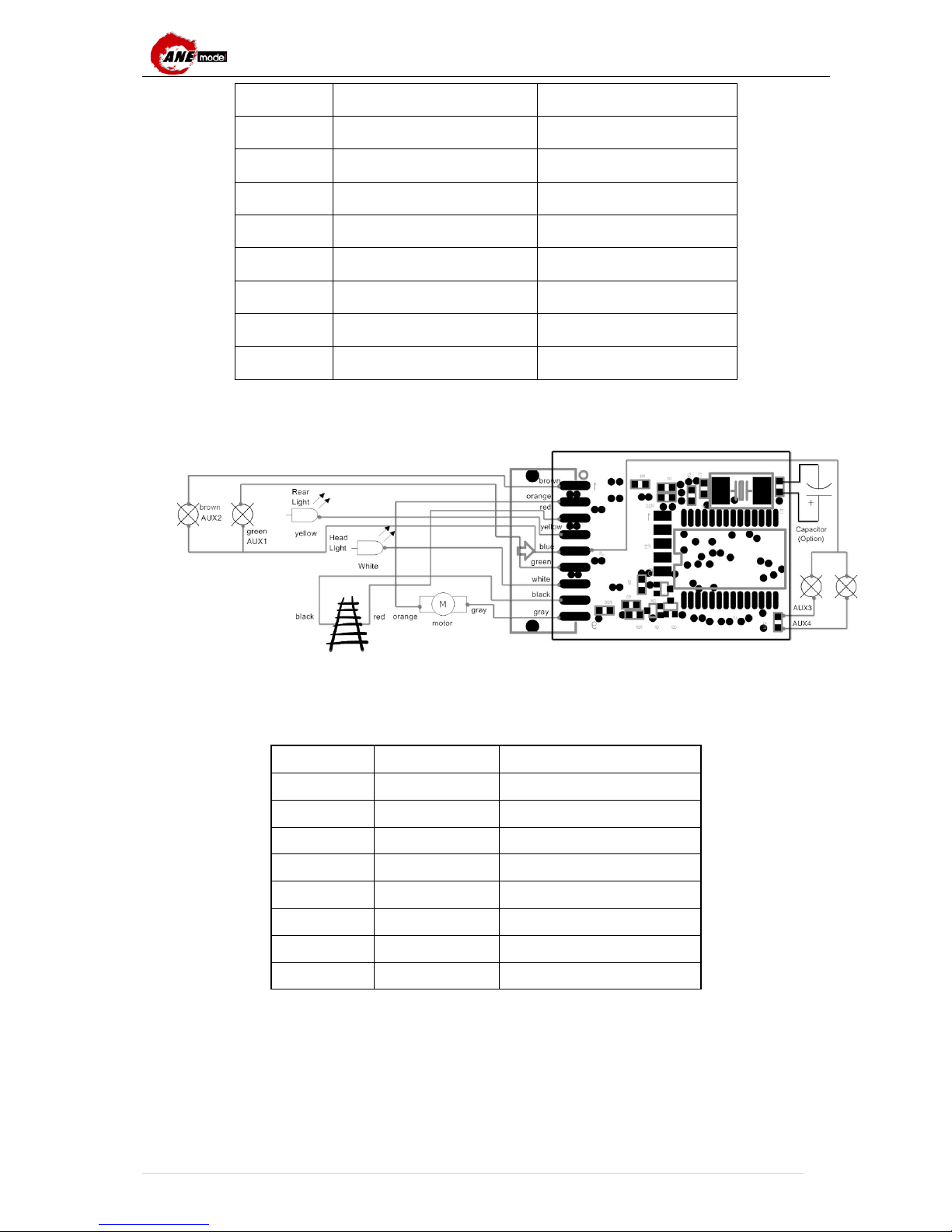
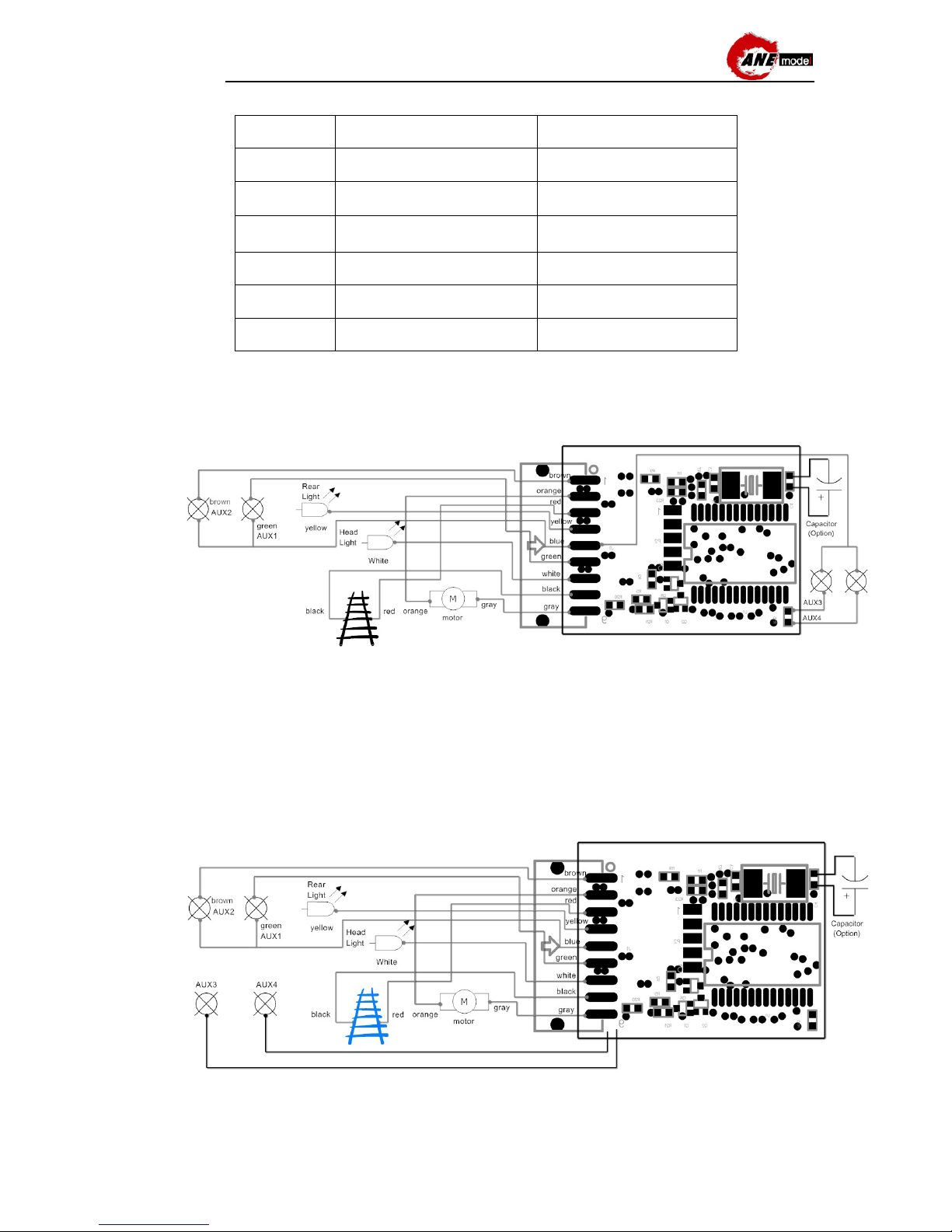
4.4.1 Wiring Diagram for LocoCruiser LC201....................................................................................7
4.5 Locomotive with 6-pin DCC-standard Interface...............................................................................7
4.5.1 Wiring Diagram for LocoCruiser LC202....................................................................................8
4.6 Locomotive with 21-pin DCC-standard Interface.............................................................................8
4.6.1 Wiring Diagram for LocoCruiser LC203....................................................................................8
4.7 Connecting Additional Functions.....................................................................................................8
4.8 Suitable Light Bulbs ........................................................................................................................9
4.9 Suitable locomotive type .................................................................................................................9
5. Initial operation .....................................................................................................................................9
5.1 DCC Mode......................................................................................................................................9
5.1.1 DCC Speed Steps (“flashing lights”).............................................................................................9
5.2 Speed control..................................................................................................................................9
5.2.1 Speed curve setting(Factory Default): .................................................................................9
5.2.2 Speed table mode...................................................................................................................10
5.2.3 Speed model Exchange.......................................................................................................... 11
5.2.4 Acceleration & Deceleration ...................................................................................................11
5.3 DC control..................................................................................................................................... 11
5.3.1 DC control method..................................................................................................................11
5.4 Engine address setting..................................................................................................................11
5.4.1 Engine address ...................................................................................................................... 11
5.4.2 Locomotive engine address setting........................................................................................ 11
5.5 Light effect ....................................................................................................................................12
5.5.1 Turn on/off light.......................................................................................................................12
5.5.2 light effect...............................................................................................................................12
5.6 CV29 setting .................................................................................................................................12
6. Decoder Settings (Programming) .......................................................................................................13
6.1 Configutation Variables (CV).........................................................................................................13
6.1.1 Standardisation in the NMRA .................................................................................................13
6.1.2 Bits and Bytes.........................................................................................................................14

LocoCruiser standard series decoder user manual Ver1.0
3
7. CV value table....................................................................................................................................14
7.1 Light function...............................................................................................................................14
7.2 Speed table.................................................................................................................................15
8. Disclosure announce..........................................................................................................................15
9.Troubleshooting...................................................................................................................................16
9.1 The Decoder is installed. After electrified, the lights do not work and the locomotive does not
move after changing speed. ...................................................................................................................16
9.2 During the locomotive moving, the moving is not continuous......................................................16
9.3 The locomotive runs normally, but the lights do not work............................................................16
9.4 Headlights work, but the locomlotive does not move...................................................................16
9.5 When I use the consist address control the loco, I have changed the value of CV17 & Cv18.
But I still can’t control the loco?.........................................................................................................16
9.6 I have followed the manual to do, but still have problems not included in the manual. What can
I do?..................................................................................................................................................16
Appendix II:Repair information.............................................................................................................16

LocoCruiser standard series decoder user manual Ver1.0
4
1.Introduction
Congratulations for choosing the ANE MODEL LocoCruiser Standard series decoder. It is designed
to give you exciting DCC control features at a reasonable price. ANE MODEL mobile decoder is
suitable for all HO scale and some N scale locomotives with space for installation.
LocoCruiser Standard decoder compliments the excellent properties of their predecessors and
expand their capabilities with extra functions. It supports the 14-step, 28-step and 128-step control
of the DCC protocol and 8 lighting effects, including dimmer, warning effect, blinking by speed effect,
random blinking effect, strobe light effect and 3 fixed-frequency blinking effects.
ANE MODEL Standard decoder should be your first choice as they can offer you flexibility and
reliability that you have come to expect to have a state-of-the-art decoder.
Caution: Please feel free to contact ANE MODEL or ANE MODEL Authorized Distributor with
any questions or concerns you might have about our products. We are always looking forward to
hearing your voice, and make our products better. Don’t hesitate to contact us!
2.LocoCruiser Standard decoder Series 2
LC201
LocoCruiser standard
Back-EMF decoder with
NMRA 8 pin plug
LC202
LocoCruiser standard
Back-EMF decoder
without NMRA 8 pin plug
LC203
LocoCruiser standard
Back-EMF decoder
with NMRA 21 pin plug
The picture of
the product
Working voltage
12V-26V
12V-26V
12V-26V
Motor current 1.5 Amp continuous and
2 Amp peak 1.5 Amp continuous and
2 Amp peak 1.5 Amp continuous
and 2 Amp peak
Function output
voltage 16V 16V 16V
Function output
max. current
300mA 300mA 300mA
Working
temperature 0—80°C 0—80°C 0—80°C
Dimension(L*W
*T) 1 "(26 mm)* 0.6" (15.5
mm)* 0.2" (5 mm) 1 "(26 mm)* 0.6" (15.5
mm)* 0.2" (5 mm)

LocoCruiser standard series decoder user manual Ver1.0
5
3. General Properties of all Decoders
3.1 Operating Modes
With the locomotive running on the layout and if you need to adjust some CV values, you don’t
have to move the locomotive to the programming track, you can adjust it through DCC
controller’s OPS mode (Operating mode), by calling up the number of the locomotive, then
modify the CV value directly. There’s one thing you need to note, OPS mode can only set
the function of the decoder. It can’t read the CV value of the decoder. If you need to adjust
the CV value precisely, then we suggest you to move the locomotive to programming track to
read and program.
3.2 Motor Control
In order to provide more perfectly running performance, ANE MODEL manufacture
LocoCruiser Series 2, especially designed a motor control program with Back-EMF function.
For a variety of locomotives, the motor will adjust output control automatically, so modellers
can experience speed control and silent running with a high standard.
3.3 Analogue Mode
According to the setting of CV29, LocoCruiser Series 2 provides you a dual mode with the loco
decoders able to run under DCC or DC control. This eliminates having to go to the trouble of
temporarily removing the DCC decoder.
3.4 Functions
LocoCruiser Series 2 has 4~6 function outputs. Each function output can reach the maximum
current of 300mA no matter weather you are controlling incandescent light bulbs or LEDs, it
can achieve your needs. At the same time, each function output has a variety of lighting
effects. From the simplest on/ off to a wide variety of lighting performance, LocoCruiser
Series 2 is your best choice! The CV value of various lighting performance are below:
CV value
Function
0 Light on
2 Strobe
4 Mars Light
8
Reverse direction
16
Forward direction
32
1/4 sec flashing
(A)
(this two effect design for ditch light)
64
1/4 sec flashing
(B)
(this two effect design for ditch light)
36 Firebox
69 Warning light
128 1/2 sec flashing
3.5 Programming
In some part of DCC controllers, there’s an individual programming track function. To connect
the programming track output with single track, put the locomotive on this track, then you can
read and program. LocoCruiser Series 2 decoders fully support the programming track
function. You can read and adjust the CV value of LocoCruiser Series 2 decoders through
the programming track, and let the Series 2 fully control the features of your locomotive as well

LocoCruiser standard series decoder user manual Ver1.0
6
as running smoothly on your layout.
3.6 Operational reliability
LocoCruiser Series 2 running decoders have passed extensive testing and functional
adaptation. It can meet the running performance of most DCC ready locomotives. You don’t
need to make any adjustments. In some particular locomotives, you may just need to make
small adjustments of CV value to reach the perfect running performance and lighting control.
We’ll publish the related information on our website, please follow the description for adjusting.
If you find that your locomotive doesn’t run smoothly after installing the ANE MODEL decoder,
please feel free to contact us at once. We will process your question promptly to make sure
that your locos run smooth and trouble free.
4. Installation
To install the decoder is not that difficult as you think. Just follow the following simple steps
carefully, you can enjoy the procedure on the instant. Each ANE MODEL decoder comes with
an instruction sheet that shows you the specifics of the decoder.
4.1Ten Steps for successful decoder installation
4.1.1 Avoiding heat problems with decoder installations
Most HO & N scale model locomotvie motors and lamps are designed by the locomotive
manufacturers to operate at full speed at 12 volts DC on the track. LocoCruiser recommends running
your DCC command station and boosters at the lowest track voltage possible that provides
acceptable operation. The “N Scale (12 V)” setting on LocoCruiser equipment works for most HO & N
scale layouts. Some DCC systems made by other companies supply more voltage to the track and
are not adjustable. If the track voltage applied exceeds the operating parameters of the locomotive
and ist lamps, it is possible for overheating to damage your locomotive whether you use DC or DCC.
For example, running an N Scale lovomocite that was designed to run on 12-14 volts on a sstem that
supplies 12 or more volts to the track may cause overheating and damage to the locomotive, its shell
and your decoder.
4.1.2 Recommended tools for decoder installation
You’ll need a few simple tools when you begin installing decoders:
1. Read the instructions FIRST and PLAN your installation
2. Have the proper tools on hand.
3. Choose a locomotive that runs well on regular DCC or DC system.
4. Choose the appropriate decoder for the installation.
5. Test the decoder before installation.
6. Carefully remove the body of the loco.
7. Plug the pins into the socket in accordance with the marks of the decoder and the
circuit board of the locomotive
8. If there’s no socket or only 6-pin socket on your loco, please choose LC202 version
decoder and follow the wiring diagram below.
9. Test the installation DCC.
10. Customize your decoder by programming selected CVs.

LocoCruiser standard series decoder user manual Ver1.0
7
1. A soldering iron, preferably temperature controlled. Though many installations do not
require soldering, you may still need to use a soldering iron to install extras like lamps
for special lighting effects.
2. Solder.
3. A small screwdriver for disassembling your loco
4. Small diagonal cutters for cutting & stripping small wire.
5. Tweezers to pick up small loco parts.
6. Heat shrink tubing for protecting wire connections, this is better than electrical tape.
7. Tape for securing wires and the decoder inside the locomotive.
8. Decoder installation should be done in a reasonably static free environment. We
recommend that you do all installations on a nonmetallic surface. LocoCruiser
decoders are not overly sensitive to static electricity & with a little common sense,
you won’t have problems.
4.2 Requirements for installation
ANE MODEL Series 2 decoders are mainly designed for OO/HO scale(1/76~1/87) locomotives
and railcars.
The different connections are listed below.
The type of decoder
Statements
LC201 With NMRA Medium 8 pin plug, apply to the locomotive with NMRA 8 pin
socket
LC202 With 9 NMRA standard wiring, so modellers can solder
directly to the
locomotive wiring
LC203 With NMRA 21pin socket, apply to the locomotive with 21pin plug
LC204 Board replacement type decoder, suitable for most locomotives which has
lack of internal space
, such as: ATLAS, Athearn, KATO USA and KATO
Japan locomotives.
LC205 These are exclusive for UK with 21pin socket / If you are interested, please
contact our UK distributor, LocoLine
LC206 The exclusive sale for UK with 8 pin socket decoder / If you are interested,
please contact with our UK distributor, LocoLine
LC201,LC202&LC206 These three types of decoder have a standard NMRA JST 9 pin connector.
You can buy the wiring harness from us, and replace the connector with 8
pin plug or without 8 pin plug.
4.3 Installation recommendations
We strongly recommend modellers confirm that the locomotive will operate normally before
installing the decoder. Also, the decoder can be tested for operation by using a Decoder
Testing Board. This, can avoid problems before installation of the decoder.
4.4 Locomotive with 8-pin DCC-standard Interface
According to the instructions in the locomotive manual, remove the body shell, and find the 8
pin socket. First, remove the dummy plug from the socket, and find the correct direction to
insert the decoder plug( Usually there’s a number or arrow marked “pin 1” on the 8 pin socket.
And then fit with 8 pin head, you’ll finish the installation.
The wire color comparison table of 8-pin DCC-standard interface

LocoCruiser standard series decoder user manual Ver1.0
8
No. Color Connect
1 Orange Motor +
2 Yellow Rear light -
3 Empty Empty
4 Black Left track
5 Gray Motor -
6 White Front light -
7 blue Common + pole
8 Red Right track
4.4.1 Wiring Diagram for LocoCruiser LC201
4.5 Locomotive with 6-pin DCC-standard Interface
Please check the wire colors are connected to the correct parts of the locomotive.
Pin No. Colour Details
1 Orange Motor +
2 Yellow Rear Light -
3 Empty Empty
4 Black Left Rail
5 Gray Motor -
6 White Front light -
7 Blue Function Common +
8 Red Right Rail
After finishing the installation, please check the motor and function wiring is completly
insulated. If not, the decoder could short out and burn out. If this happens then the decoder
will not be covered by warranty. Please be careful!

LocoCruiser standard series decoder user manual Ver1.0
9
The wire color comparison table of 6-pin DCC-standard interface
No. Color Connect
1 Orange Motor +
2 Gray Motor -
3 Red Right track
4 Black Left track
5 White Front light -
6 Yellow Rear light -
Please make sure all connected wires are correct. Connecting wrong wire could destroy the
decoder.
4.5.1 Wiring Diagram for LocoCruiser LC202
4.6 Locomotive with 21-pin DCC-standard Interface
According to the instructions in the locomotive manual, remove the body shell, and find the 21
pin plug. First, remove the plug from the socket and find the correct direction( Usually there’s a
number or arrow marked “pin 1” on the 8 pin head. And then fit with 8 pin head, you’ll finish the
installation.
4.6.1 Wiring Diagram for LocoCruiser LC203
4.7 Connecting Additional Functions
The Series 2 decoders have 4~6 additional functions. Each function output can reach
300mA.

LocoCruiser standard series decoder user manual Ver1.0
10
4.8 Suitable Light Bulbs
Each function output can directly connect with 12 v bulb, unless the locomotive instructions
say it cannot support the voltage of the blub.
4.9Suitable locomotive type
The ANE MODEL LocoCruiser standard decoder is suitable for all HO scale and some N scale
locomotives (size permitting). The decoder is fully compatible with NMRA/DCC standards
and can be controlled by various DCC (digital command control) systems which are
compatible with DCC standards. Operating by conventional DC controller is possible without
any problems.
5. Initial operation
5.1 DCC Mode
Remove any capacitors that are wired into the track feeders. This could impair
the functionality of the decoder.
The LocoCruiser works with any DCC system. Unfortunately, the DCC protocol
also bring some difficulties into the game. One of them occurs so often that we
deal with it right away.
5.1.1 DCC Speed Steps (“flashing lights”)
“Lights do not work “ with DCC systems: DCC locomotives run with 14, 28, or
128 speed steps. The decoder must”know” the speed step setting of the
command station. The command station must be able to operate with this mode
and must be set accordingly. If this is not the case, the following problems may
occur:
1. You cannot switch the lights with F0 at all.
2. The lights keep switching on and off dependent on the speed step.
In this case, make sure that the speed step settings of decoder and
command station are the same.
5.2 Speed control
There are two speed control settings: the speed curve setting and the speed table setting.
5.2.1 Speed curve setting(Factory Default):
The speed curve setting is to set the starting voltage in CV2, the maximum voltage in CV5
and the medium point voltage in CV6. In order to explain more, the speed step and the
speed value are represented with a curve in an axis graph. In the following 4 figures (from
4-1 to 4-4), the horizontal line represents the speed step while the vertical line represents
the speed value. The speed of the locomotive is divided into 28 steps in the speed step
line. Thus, each step represents one speed step and the value is from 0 to 28. The speed
value is the current speed of the locomotive and the value is from 0 to 255. The 14-step
and the 128-step settings are similar with the curves. The 14-step speed setting is 14, the
middle speed will be 7-step; on the other hand, when the loco is under 128-step speed, the
middle speed will be 64-step.

LocoCruiser standard series decoder user manual Ver1.0
11
Figure 4-2:Speed curve with CV6 > CV5/2
You can see the change from the figure 4-2. If CV6>CV5/2:
When the speed value is less than the middle value 14 (i.e., in a low speed status), the
speed change is fast.
When the speed value is higher than the middle value 14 (i.e., in a high speed status), the
speed change is slow.
Figure 4-3:Speed curve with CV6=CV5/2
You can see the change from the figure 4-3. If CV6=CV5/2, both the high and low speed
change are slow. It’s the same result for the speed curve with CV6=0 or 1.
5.2.2 Speed table mode
The speed curve is divided into 28 steps in the speed table mode. Each speed value
responds the values from CV67 to CV94 (as per figure 4-4).
Figure 4-4:Speed table
In the speed table mode, to modify the CV of the co-responding speed step means to
modify the value of the speed step to achieve a different result.
Figure 4-1:Speed curve with CV6 < CV5/2

LocoCruiser standard series decoder user manual Ver1.0
12
5.2.3 Speed model Exchange
Setting bit 4 of CV29 enables to switch the two modes. The speed curve mode is activated if
the value is 0; If the value is 1; the speed table mode is activated (default setting)
5.2.4 Acceleration & Deceleration
The final acceleration of the locomotive is determined by the value of CV3; on the other
hand, the deceleration is determined by the value of CV4.
The higher the acceleration(CV3)/deceleration(CV4)value, the higher the final
acceleration/deceleration. That is to say, the acceleration/deceleration speed of the
locomotive is lower. The lower the value is, the lower the final acceleration/deceleration is.
That is to say, the acceleration/deceleration speed of the locomotive is higher.
5.3 DC control
5.3.1 DC control method
Using a conventional DC controller to operate is possible without any problem. You can
run a locomotive that already has the ANE MODEL LocoCruiser Standard series decoder
installed, on 16VDC track. DC environment does not support Back-EMF function and
lighting effect.
5.4 Engine address setting
5.4.1 Engine address
The engine address indicates the assigned numbers of the moving locomotives on the track.
Setting the engine address will enable you to control the locomotives by the DCC controller.
The following describes show the definitions of DCC protocol’s engine address.
CV1:Engine address
CV17&CV18:Extended engine address
CV19: Consist address
The priority of the 3 engine addresses which are defined in the DCC protocol is: Consist
address>Extended engine address >Engine address
5.4.2 Locomotive engine address setting
The first priority is the Consist address of CV19. The locomotives are under the control of
the Consist address unless the value is 0 or 128. As for the “Extended engine address”
(CV17&CV18) and the “Engine address” (CV1), if the value of the Extended engine address
is not 0 and the value of bit5 of CV29 is 1, the locomotives will be under the control of the
Extended engine address. If the value of the Extended engine address is 0 or the value of
CV29 bit5 is 0, the locomotives are under the control of the Engine address.
Chapter 6 of this manual will show you the CV values. You can find the CV values which
related to the engine address. The range of CV19 value that responds to the Consist
address is from 1 to 127 and from 129 to 255. If the value of CV19 is larger or equal to 1
and is smaller and equal to 127, the locomotive will agree with forward direction. At this
time, the locomotive is under the control of the address 1-127. If the value of CV19 is
larger or equal to 129 and is smaller and equal to 255, the locomotive will accept the
opposite direction. At this time, the locomotive is under control of the address (CV19
value-128).
The range of the Extended engine address (CV17&CV18) value is 128-9999. The value is
according to the value of the lowest 6 bits of the CV17 combines with the 8 bits of CV18.

LocoCruiser standard series decoder user manual Ver1.0
13
5.5Light effect
5.5.1 Turn on/off light
The LocoCruiser standard series Decoder is equipped with 5 fixed lighting outputs. The
relative values are stored in CV33 to CV37. The table 4-1 shows their default settings:
CV Function Default Range
33 F0F (on/off) 1 1,
2,
4,
8,
16,
32,
128
34 F0R(on/off) 2
35 F1(on/off) 4
36 F2(on/off) 8
37 F3(on/off) 16
95 F4(on/off) Not yet open
Table 4-1: Lighting output on/off allocation (F0F is front light and F0R is rear light)
Note:
Value =1 control by F1
Value =2 control by F2
Value =16 control by F0
Value =128, always light on.
5.5.2 light effect
The CV33, CV34 values just effect the turn on or off status. However, the LocoCruiser
standard series Decoder is featured with 10 lighting effects including the dimmer, the
warning effect, the blinking per speed effect, the random blinking effect, the strobe light
effect and 3 fixed-frequency blinking effects. Understanding more about the CV49 to CV53
will help you adjusting the CV settings to bring you more than one thousand of lighting
effects. The information of CVs, outputs and light effects are shown in table 4-3 as below.
CV Function Default Range
Record your number in
here
49 FOF light effect 16 0-255
50 FOR light effect 8 0-255
51 F1 light effect 0 0-255
52 F2 light effect 0 0-255
53 F3 light effect 0 0-255
96 F3 light effect
Not yet
open
0-255
Table 4-2: Light effect allocation
5.6 CV29 setting
CV29 related to the operating efficiency of the decoder. The performance of every bit switch
will have a significant impact on the decoder. In order to allow the modelers can easily adjust each
bit of CV29, we make list of CV29 switch setting in particular in the following table, so you can refer
to each different needs to adjust.
CV29
Bit 0
Bit 1
Bit 2
Bit 3
Bit 4
Bit 5
Value
Function
description Reverse
direction of
loco
14 or
28/128
speed
steps
DC analog
operation Bi-direction
control (Not
release)
Speed
table Long
address

LocoCruiser standard series decoder user manual Ver1.0
14
-- -- -- -- -- -- 0
Open
--
--
--
--
--
1
-- Open -- -- -- -- 2
Open Open -- -- -- -- 3
-- -- Open -- -- -- 4
Open
--
Open
--
--
--
5
default
--
Open
Open
--
--
--
6
Open Open Open -- -- -- 7
-- -- -- -- Open -- 16
Open -- -- -- Open --
17
-- Open -- -- Open -- 18
-- -- Open -- Open -- 20
-- Open Open -- Open -- 22
Open
Open
Open
--
Open
--
23
-- -- -- -- -- Open 32
Open -- -- -- -- Open 33
Open -- -- -- Open 34
Open
Open
--
--
--
Open
35
--
--
Open
--
--
Open
36
Open -- Open -- -- Open 37
-- Open Open -- -- Open 38
Open Open Open -- -- Open
39
-- -- -- -- Open Open 48
Open -- -- -- Open Open 49
-- Open -- -- Open Open 50
Open
Open
--
--
Open
Open
51
-- -- Open -- Open Open 52
Open -- Open -- Open Open 53
-- Open Open -- Open Open 54
Open
Open
Open
--
Open
Open
55
6.Decoder Settings (Programming)
6.1 Configutation Variables (CV)
Almost all configuration Variables (CVs) LocoCruiser decoders follow the CV concept
developed in the US. CV stands for “Configuration Variable” and indicates that the storage
cells described above are not only variable but they also determine the behavior of the
decoder.
6.1.1 Standardisation in the NMRA
The NMRA ( National Model Railroad Association) has defined which CVs determine certain
parameters of a decoder. The DCC standard allocates fixed numbers for certain CVs
( adherence is obligatory). This greatly simplifies things for the user since decoders of most
manufacturers comply with this standard and therefore dealing with CVs requires the same
process with the same CV-numbers regardless of the manufacturer.
The DCC concept permits to enter numbers ranging from 0 to 255 into CVs. Each CV carries
only one number. While the position number is predetermined, the range of values may vary.

LocoCruiser standard series decoder user manual Ver1.0
15
Not all CVs must accept values ranging from 0 to 255. The permitted values for LocoCruiser
decoders are listed in the table in chapter 7 showing all available CVs.
6.1.2 Bits and Bytes
Most CVs contain numbers: CV1 for instance contains the locomotive address. This can be
any number between 1 and 127. While most CVs expect numbers to be entered, some
others are rather like a “ collection point” of various”switches”, that administer different
functions in one CV (mainly ”on” or “off”): CVs29 and 49 are good examples: you must
calculate the value for these CVs yourself. The value depends on which settings you want to
program:
Have a look at the explanations for CV29 in the table in chapter 7: firstly, decide which
options should be active. The column “Value” has two numbers for each option. If the option
is switched off, the value is 0. Otherwise, it is a number between 1 and 128.
Add all the values for the respective options to arrive at the correct value for this CV.
7. CV value table
CV Function Default Range Remark
1
Engine address
3
1
-
127
CV29value
adjustment, please
see the chapter 5.6
2 Start voltage 1 1-CV6 value
3 Acceleration 5
0
-
255
4 Deceleration 5 0-255
5 Maximum speed 0 CV6-255 value
6 Medium speed 0 CV2-CV5 value
7 Version number 201 Cannot be revised
8
Manufacturer’s ID
45
Cannot be revised
10
EMF Feedback Cut-out
255
0
-
255
17 Extended engine high
address 192 192-255
18 Extended engine low address 0
0
-
255
19
Consist address
0
0
-
255
29
Configuration register
6
0
-
255
7.1 Light function
Function Default Range
Record your number in here
Remark
33 F0F (on/off) 1 1,
2,
4,
8,
16,
32,
128
34 F0R(on/off) 2
35 F1(on/off) 4
36 F2(on/off) 8
37 F3(on/off) 16
95 F4(on/off) 32
49 FOF light effect 16 0-255
50 FOR light effect 8 0-255
51 F1 light effect 0 0-255
52 F2 light effect 0 0-255
53 F3 light effect 0 0-255

LocoCruiser standard series decoder user manual Ver1.0
16
96 F4 light effect 0 0-255
7.2 Speed table
Function
Default
Range
Remark
67
Speed Table 1
1
0-255
68
Speed Table 2
6
0-255
69
Speed Table 3
12
0-255
70
Speed Table 4
16
0-255
71
Speed Table 5
20
0-255
72
Speed Table 6
24
0-255
73
Speed Table 7
28
0-255
74
Speed Table 8
32
0-255
75
Speed Table 9
36
0-255
76
Speed Table 10
42
0-255
77
Speed Table 11
48
0-255
78
Speed Table 12
54
0-255
79
Speed Table 13
60
0-255
80
Speed Table 14
68
0-255
81
Speed Table 15
76
0-255
82
Speed Table 16
84
0-255
83
Speed Table 17
92
0-255
84
Speed Table 18
102
0-255
85
Speed Table 19
112
0-255
86
Speed Table 20
124
0-255
87
Speed Table 21
136
0-255
88
Speed Table 22
152
0-255
89
Speed Table 23
168
0-255
90
Speed Table 24
188
0-255
91
Speed Table 25
208
0-255
92
Speed Table 26
230
0-255
93
Speed Table 27
252
0-255
94
Speed Table 28
255
0-255
8. Disclosure announce
This warranty excludes the LocoCruiser standard series Decoder malfunction under the
following reasons:
♦User does not follow the instructions to install the Decoder, causing the product to be
damaged or malfunction.
♦User does not follow the instructions to operate the Decoder and make the product
damaged or malfunction.
♦User disassembles or replaces the component of the product by himself, then makes the
product damaged or malfunction.
♦The product is corroded, ignited or broken, because of improper management by user so
that the product cannot work normally.
♦User does not follow the instructions in this manual to operate the product, which causes
damage or malfunction.
The right of the above declaration belongs to ANE Model.
9. Troubleshooting
Some reasons may cause the LocoCruiser standard series Decoder not to work as desired.

LocoCruiser standard series decoder user manual Ver1.0
17
Here are some frequently asked questions and the answers that may help you use the
product properly.
9.1 The Decoder is installed. After electrified, the lights do not work and the
locomotive does not move after changing speed.
Check if the wires are fitted properly.
Check if any short circuits between the DCC control and the track.
9.2 During the locomotive moving, the moving is not continuous.
Check if the track is clean.
Check if the wires are fitted properly and good connections.
9.3 The locomotive runs normally, but the lights do not work
If the lights do not work, check if the wires are fitted properly. Repeatedly press the light
button then see if something has changed.
Read the CV value that activates the lights and check if the lights are turned off. Refer
to Chapter 5.3.1 for more detail.
If the problem remains, please ask our dealer for a new unit.
9.4 Headlights work, but the locomotive does not move
Read the value of CV1 and check if the engine address is different from the Decoder.
Rewrite the engine address.
9.5 When I use the consist address to control the loco, I have changed the
value of CV17 & CV18. But I still can’t control the loco?
Please check the CV29, bit 5 value. If the value of bit 5 is not 1, please change to 1.
9.6 I have followed the manual to do, but still have problems not included
in the manual. What can I do?
If you still can’t solve the problems, please contact us via E-mail or telephone, we will
reply to you as soon as possible.
Appendix II:Repair information
ANE Model provides you with the warranty and service for LocoCruiser standard series decoder
as the following:
1、The LocoCruiser standard series decoder is replaced free of charge within 90 days and
repaired free of charge within one year after purchasing.
2 、After the free-of-charge repair period (one year), the LocoCruiser standard series Decoder
provides a lifelong repair service with charge.
This manual suits for next models
2
Table of contents
Popular Media Converter manuals by other brands

Hengstler
Hengstler AC 58 Interbus installation instructions

RGBlink
RGBlink CP 3072PRO user manual

Littfinski Daten Technik
Littfinski Daten Technik LS-DEC-8x2-B Assembly instruction

Lenze
Lenze 8200 motec Mounting instructions

KROHNE
KROHNE IFC 010 K Installation and operating intructions

Soundstream
Soundstream iCQ.2 operating manual