moyno 2000 User manual

MOYNO
®
2000 Pumps
G2/G3 Enhanced Feed Models
Version 5 Models
SERVICE MANUAL

Note: This service manual outlines installation, operation and maintenance procedures for the flanged ”G4” models of Moyno 2000
pump. For information on the flanged G1, open throat (G2) and/or the bridge breaker (G3) models of the Moyno 2000 pump,
refer to their respective Service Manual, or contact your nearest Moyno pump representative.
TABLE OF CONTENTS
Page
1-1. INTRODUCTION……………………………….....
1
1-2. GENERAL…………………………………1
1-3. NAMEPLATE DATA……………………...1
1-4. Pump Rotation…………………1
1-5. Model Number…………………1
1-6. Frame Size Designation………1
1-7. Type Designation……………...1
1-8. Version Designation………….. 2
1-9. Trim Code……………………... 2
1-10. Variation of Standard Parts…..2
2-1. INSTALLATION……………………………………2
2-2. GENERAL…………………………………2
2-3. PIPING……………………………………. 2
2-4. Suction Piping………………….2
2-5. Discharge Piping………………2
2-6. FOUNDATION…………………………… 2
2-7. SHAFT ALIGNMENT……………………. 3
2-8. On Coupling Connected Units. 3
2-9. On Belt Drive Units…………… 3
2-10. WATER FLUSH OF PACKING………..3
3-1. OPERATION…………………………………….... 3
3-2. INITIAL CHECK…………………………..3
3-3. START-UP……………………………….. 3
3-4. PACKING LEAKAGE…………………….4
4-1. MAINTENANCE……………………………………4
4-2. GENERAL…………………………………4
4-3. PACKING ADJUSTMENT……………….4
4-4. PACKING REPLACEMENT……………..4
4-5. LUBRICATION……………………………5
4-6. Bearings………………………...5
4-7. Gear Joints……………………..5
4-8. PUMP DISASSEMBLY……………..…... 5
4-9. Disconnect Pump……………...5
4-10. Packing Removal……………...5
4-11. Stator Removal……………….. 5
4-12. Drive train removal………..….. 5
4-13. Rotor, Connecting Rod, and
Intermediate Shaft Removal .. 6
4-14. Drive Shaft and Bearings
Removal………………………..6
4-15. G3 BRIDGE BREAKER
DISASSEMBLY…………………………6
4-16. G3 Paddle Removal………..… 6
4-17. G3 Bearing Side Removal..…..6
4-18. G3 Drive Side Removal……… 6
Page
4-19. CLEANING……………………………..7
4-20. INSPECTION…………………………..7
4-21. Bearings…………………..….. 7
4-22. Drive shafts………………..….7
4-23. Seals……….……………..….. 7
4-24. Packing…….……………….... 7
4-25. Rotor…….………………..….. 7
4-26. Stator…….………………..….. 8
4-27. All Other Parts……………….. 8
4-28. PUMP ASSEMBLY ……………………8
4-29. Lubrication During Assembly. 8
4-30. Packing Installation…………. 8
4-31. Bearing Housing/Suction
Housing Assembly…………... 8
4-32. Bearing/Drive Shaft
Assembly……………………...8
4-33. Rotor/Stator Assembly……… 9
4-34. Rotor Gear Joint Assembly… 9
4-35. Rotor/Stator to Drive End
Assembly……………………...10
4-36. Stator Support/Discharge
Assembly…………………….. 10
4-37. G3 BRIDGE BREAKER ASSEMBLY .11
4-38. G3 Drive Side Assembly…….11
4-39. G3 Bearing Side Assembly …11
4-40. G3 Paddle Assembly …….….11
4-41. FINAL ASSEMBLY…………………….12
4-42. Packing Adjustment……..….12
4-43. OTHER CONSIDERATIONS…………12
4-44. Short Term Storage .………. 12
4-44. Long Term Storage .………. 12
4-46. PACKING SPECIFICATION………….12
4-47. VARIATIONS OF STANDARD PARTS.
12
4-48. Rotors……..…………….……. 13
4-49. Drive Shafts……………...….. 13
4-50. PUMP MODEL DESIGNATION…..… 13
4-51. G2 PARTS LISTS………………….…. 14
4-52. Table 4.1 G2 Exploded View15
4-53. G3 PARTS LISTS………………….…. 16
4-54. Table 4.2 G3 Exploded View.17
4-55. TROUBLESHOOTING CHART…..…. 18
1
SERVICE MANUAL
Moyno
®
2000 Pumps
G2/G3 Enhanced Feed Open Throat Models
1-1. INTRODUCTION
1-2. GENERAL
The Moyno
®
2000 Pump is the culmination of over 70 years of
experience in manufacturing and marketing fluids handling
equipment. This rugged pump has been engineered to be the most
reliable product ever sold under the Moyno name. The pump has
been painstakingly tested to assure consistent performance in the
most difficult of applications. Itrepresents thenextgeneration of the
world’s most versatile pump.
The Moyno 2000 Pump is a progressing cavity pump. A single
helical rotor rolling eccentrically in the double helix of the stator
creates the pumping action. The rotor in conjunction with the stator
forms a series of sealed cavities 180 degrees apart. s the rotor
turns, the cavities progress from the suction to the discharge. As
one cavity diminishes, the opposing cavity increases at exactlythe
same rate. Thus the sum of the two discharges is a constant
volume. The result is a pulsation-free positive displacement flow
utilizing no valves.
The G2 product line is thelatest Moyno design whichincorporates a
wide open throat feed hopper with auger connecting rod for better
fill efficiency. The G3 version incorporates the features of the G2
open throat plus has a separate bridge breaker mechanism to
effectively pump even higher solids and viscosity products. This
manual supports the G2/G3 version 5 product lines purchased after
Oct 2003 (See fig 1-1 for indicator in trim code).
G2 Version 5 features include integral extension tube, larger auger
feed connecting rods, and two piece drive shaft for easy
maintenance. TheG3Version 5includesthefeatures oftheG2 plus
separate drive on the Bridge Breaker to allow the flexibility to vary
the paddle speed, separate from the pump, when needed. The
paddle shaft is designed for maintenance ease by allowing the
paddles to be removed from the inside of the suction hopper. This
feature allows servicing of the bottom pump portion without
disturbing the bridge breaker drive mechanism, significantly
reducing downtime.
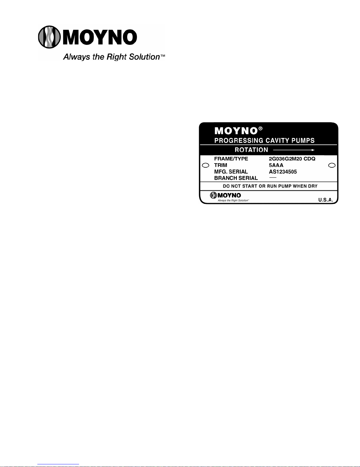
1-3. NAMEPLATE DATA
The pump nameplate, located on the bearing housing, contains
important information relating to the operation and servicing of the
pump. This information includes the direction of rotation arrow and
the pump model and serial numbers (see Figure 1-1.). The pump
model number must be used for reference when ordering spare
parts.
1-4. Pump Rotation. A rotation arrow on the nameplate indicates
the direction of rotation. Normal rotation of Moyno 2000 pumps is
clockwise, when viewed from the driven end of the pump.
Figure 1-1. Typical nameplate showing rotation arrow,
model, and manufacturing serial numbers.
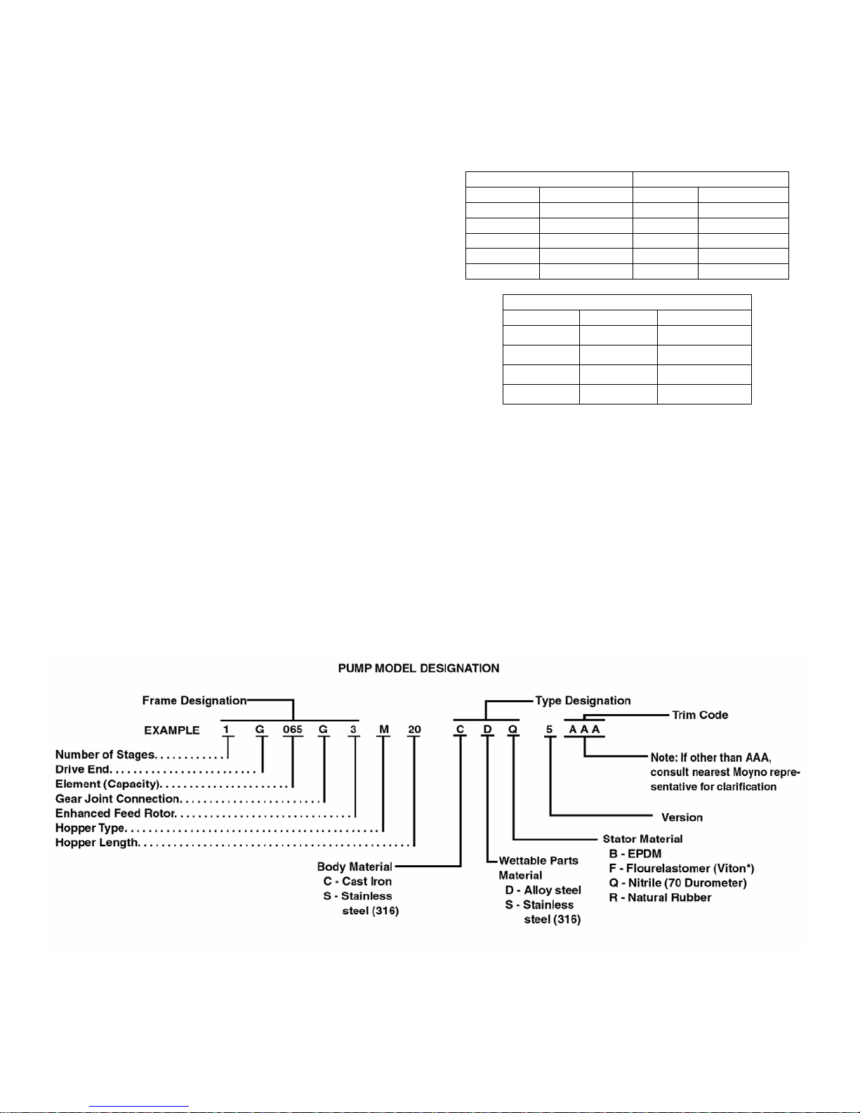
1-5. Model Number. The pump model number consists of
three componentparts:Frame Designation,TypeDesignation
and a Trim Code. A typical model number, for example, might
be 2G036G2M20 CDQ 5AAA, as shown on the nameplate in
Figure 1-1. Version #5 is indicated before the trim code (IE:
5AAA).
1-6. Frame Designation. The Moyno 2000 is modular in
concept allowing for optimal matchingof driveends andpump
elements (rotor and stator) to meet the requirements of the
application. The ten or more characters in the frame
designation describe the particular combination of drive end,
hopper length, and pump elements, as well as other
construction details of your pump. The first character in the
frame designation, always a number, indicates the number of
stages of the pump elements.
The second character is always a letter (E-K) and indicates
the drive end size. The third, fourth and fifth numerical
characters are indicating the theoretical capability of
the
pumping elements per 100 revolutions on water. The sixth
character represents the type of universal joint utilized, “G” =
gear type joint. The seventh character, a number, indicates
the type of suction housing. Open throat pumps are
designated by a “2”, open throat pumps with a bridge breaker
option by the numeral “3”. On the G2 and G3 versions, the
eighth character is a letter that represents the type of hopper
and auger style used. The length of the hopper is designated
by the ninth and tenth numerical characters. A length
designation of 20 indicates a hopper length made to mate to 2
meter belt filter press (2.2 meters wide).
1-7. Type Designation. Following the Frame Designation is
the Type Designation, a series of three letters describing the
materials from which the pump is constructed.
Section: MOYNO
®
2000 G2/G3 PUMPS
Page: 1
Date: October 2005
2
The first letter identifies the material of the suction housing.
C ⎯Cast Iron
E ⎯Carpenter 20 Stainless Steel*
G ⎯416 Stainless Steel
H ⎯Hastelloy “C”**
J ⎯17-4 pH Stainless Steel
M ⎯Monel***
S ⎯316 Stainless Steel
W ⎯Cast Steel
X ⎯Special to Application
The second letter indicates the material used in the drive shaft,
connecting rod, rotor, and other wettable parts.
D ⎯Alloy Steel
E ⎯Carpenter 20 Stainless Steel*
G ⎯416 Stainless Steel
H ⎯Hastelloy “C”**
J ⎯17-4 pH Stainless Steel
M ⎯Monel***
S ⎯316 Stainless Steel
X ⎯Special to Application
The third letter indicates the material of the stator. It identifies
only the stator material and not that of the tube. The stator tube
construction is typically carbon steel since it is isolated from the
pumpage. Standard stator materials used in the Moyno 2000
pump are as follows:
B ⎯EPDM 300, 70 Durometer
C ⎯Nitrile 103, 50 Durometer
D ⎯Tool Steel
E ⎯Nitrile 110, 70 Durometer
F ⎯Fluoroelastomer 500, 75 Durometer
G ⎯416 Stainless Steel
H ⎯Hastelloy “C”**
I ⎯Teflon 15% Glass†
J ⎯17-4 pH Stainless Steel
K ⎯Hypalon 800, 70 Durometer†
M ⎯Nitrile 100M 70 Durometer
P ⎯Thiokol 70 Durometer‡
Q ⎯Nitrile 100, 70 Durometer
R ⎯Natural Rubber 200, 55 Durometer
T — Teflon 15% glass
U ⎯Urethane 70 Durometer
X ⎯Special to Application
Z ⎯White Nitrile 150, 70 Durometer
A typical type designation, such as CDQ, would identify the
following materials of construction:
C ⎯Cast iron suction housing
D ⎯Alloy steel rotor, drive shaft, connecting rod and
other minor metallic parts in contact with the fluid being
pumped.
Q ⎯Nitrile (70 Durometer) stator
*Carpenter 20 is a trademark of Carpenter Technology Corp.
**Hastelloy is a trademark of Cabot Corp.
***Monel is a trademark of INCO Alloy Corp.
†Hypalon and Teflon are trademarks of E. I. DuPont de Nemours
and Company
‡Thiokol is a trademark of Morton Thiokol, Inc.
1-8. Version Designation. Following the Frame Designation is
the a number which indicates the version Designation. A metric
version sold into the world markets is designated as a 1. The
current ANSI version, covered in this service manual, is
designated by 5.
1-9. Trim Code. Also included in the Model Number is the
three character Trim Code which is used to identify pump
construction. The letters “AAA” signify standard construction,
with letters other than “A” signifying variations. The first letter
identifies sealing variations; the second, internal variations;
and the third, rotor variations.
1-10. Variations of Standard Parts. Refer to Sections 4-47
through 4-49 for variations available for modifying pumps to
meet specialized pumping conditions. If the trim code of your
pump is other than “AAA”, contact your nearest Moyno
representative for clarification. Do not modify your pump with
any variation unless you have determined that it is compatible
with your application.
2-1. INSTALLATION
2-2. GENERAL
Moyno pumps are lubricated and tested at the factory prior to
shipment and require minimum pre-start up maintenance.
Packing, however, is not lubricated at the factory.
Accessibility to the pump and adequate clearance should be a
prime consideration in any installation. Enough space should
surround the unit so that maintenance can be carried out with
ease.
2-3. PIPING
2-4. Suction Hopper usedwithopenthroat and bridgebreaker
pumps should have nearly vertical sides, or be otherwise
designed to enhance the flow of the material into the pump.
2-5. Discharge Piping diameter should generally be as large
as the pump ports unless fluid conditions indicate otherwise.
An easily removable section of piping one-to-two times longer
than the connecting rod (approximately the length of the
suction housing and bearing housing together) should be
mated to the discharge port. This will allowthe rotor and stator
to be removed without having to remove the complete pump
from the base.
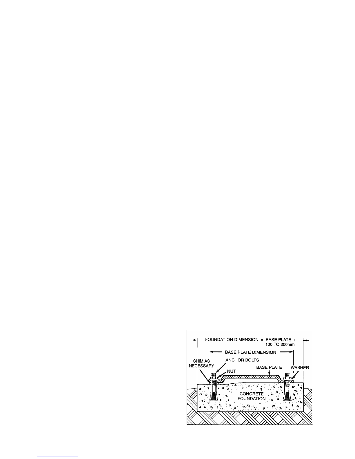
2-6. FOUNDATION
Each unit should bemounted on a strong,fabricatedsteelbase
plate. The base plate should be mounted on a concrete
foundation. The foundation should be approximately 4” to 8”
longer and wider than the base for which it is built (See Figure
2-1.). Anchor bolts for the base plate should be located in the
foundation.
Figure 2-1. Typical Foundation Example
3
Check the base plate surface with a carpenter’s level and
place shims under the base plate at the places necessary to
make it level. Then check the pump driver shaft and the
pump ports to ensure that they are level. Complete base
mounted units supplied by Moyno including pump and driver
are leveled with respect to the base at the factory. Shifting
may occur during shipment. The pump and driver should be
realigned. Care should be exercised to ensure that all
components are level and mounted in a direct line.
For maximum rigidity and lower noise levels, the base plate
should be grouted to the foundationafterthe anchor boltshave
been evenly tightened. A good grade of non-shrink grout is
recommended. The spaces between the base plate and the
foundation around the shims should also be filled with grout.
Allow the grout to dry according tomanufacturers’ instructions,
then fully tighten the anchor bolts.
2-7. SHAFT ALIGNMENT
Although the base-mounted units supplied by Moyno are
leveled with respect to the base before shipment, most of the
larger pump and driver units are shipped with the flexible
coupling disconnected.
After the base has been bolted down to the foundation, check
the following conditions:
2-8. On Coupling Connected Units, be sure that the pump
and driver shafts are realigned before the coupling is
connected. Care should be exercised to ensure that all
components are level and mounted in a direct line.
Check gap between coupling halves (refer to coupling
manufacturer’s recommendations). Adjustmentcan usuallybe
accomplished by loosening the mounting bolts on either the
pump or driver and moving the loosened component into
alignment with the fixed component. On couplings with equal
diameter hubs, it may be possible to lay a straight edge axially
across the coupling halves to check alignment.
Check gear reducer and motors for proper lubrication per
manufacturer’s recommendations.
2-9 On Belt Drive Units, check to ensure that sheaves or
sprockets are in alignment. Check belts for proper tension.
Tension requirements will vary with type of belt, center
distances, and belt speeds. Consult belt manufacturer for
specific recommendation.
2-10. WATER FLUSH OF PACKING
The packing maybe either grease lubricated through agrease
fitting in the stuffing box or have plumbing connected to the
housing to allow for water flushing.
Packing is not grease lubricated at the factory prior to
shipping.
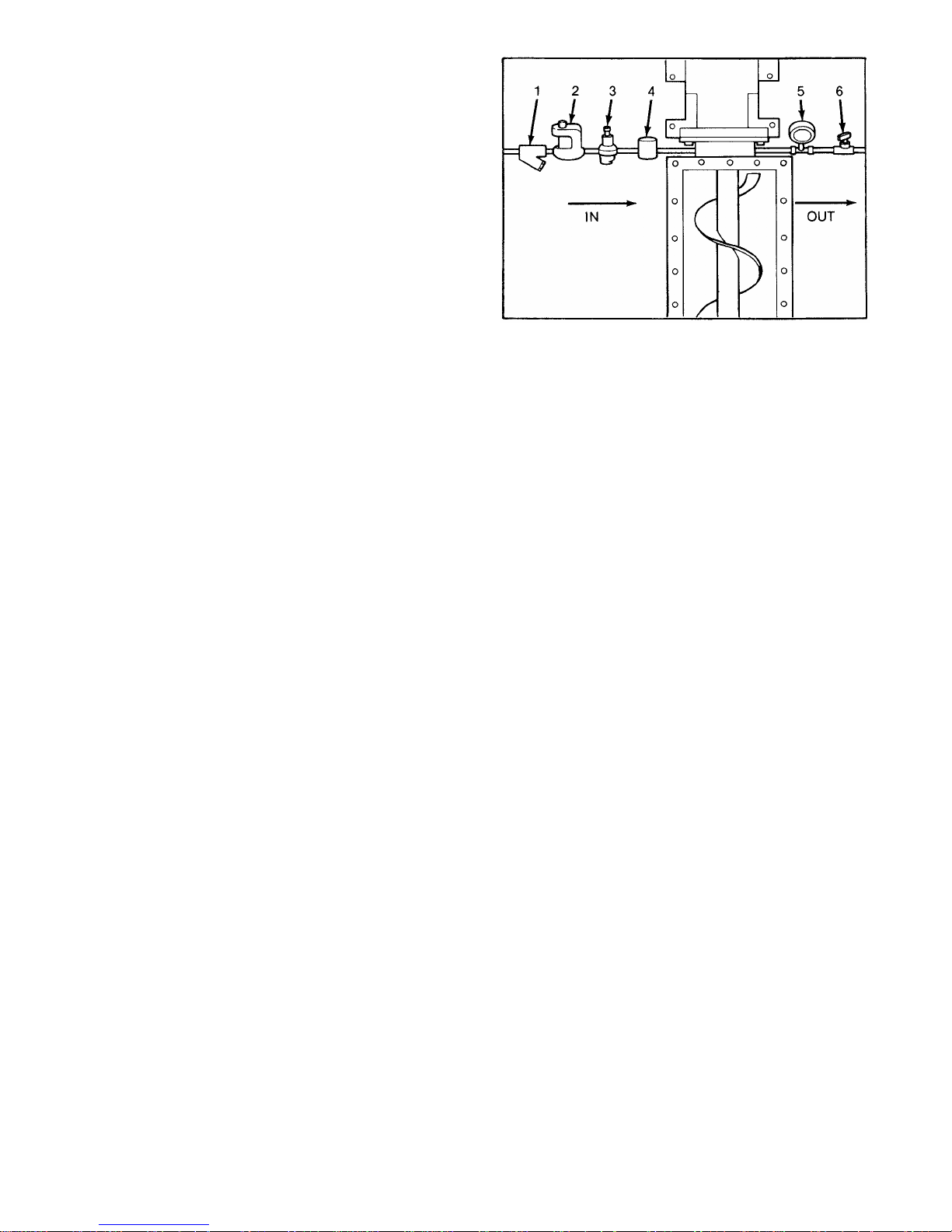
When the material being pumped is abrasive, water flushing
the packing is recommended to extend shaft life.
Clean water can be injected through a 1/8” NPT hole that
normally houses the grease fitting for lubricating the packing.
The water should be permitted to leak axially along the shaft
and be removed from the second tapped hole in the stuffing
box. The discharge from the stuffing box should be throttled
slightly to maintain 10 – 15 PSI higher pressure in the stuffing
box than is present in the suction housing (See Figure 2-2.).
Flow rate should be approximately ½ - 2 GPM.
If a mechanical seal is used, consult the seal manufacturer’s
instructions for seal flush requirements.
Figure 2-2. Typical water flush arrangement for units with
packing includes strainer valve (1), pressure regulating
valve (2), sight flow meter (3), solenoid valve (4), pressure
gauge (5), and needle valve (6).
3-1. OPERATION
3-2. INITIAL CHECK
Before putting the pump into operation, the following items
should be checked to ensure that each piece of equipment is
installed correctly:
⎯Pump, driver, coupling, or sheave alignment.
⎯Electrical connections.
⎯Gauges and other instruments.
⎯Water flush connection to the stuffing box.
⎯Pump rotation. Normal rotation is indicated on the
nameplate on the bearing housing.
⎯- G3 Bridge Breaker rotation. Normal rotation is for paddles
to rotate inward
⎯All valves should be open on both suction and discharge
sides of the pump.
⎯- Check for foreign objects in suction hopper.
CAUTION: This is a positive displacement pump. Do not
operate it against a closed valve.
3-3. START-UP
CAUTION: DRY OPERATION IS HARMFUL TO THE PUMP!
Never allow the pump to operate without liquid, as dry
operation will cause premature wear of the stator and
possible damage. The stator is lubricated by the liquid,
which is pumped.
1. Before operating the pump for the first time, fill it with liquid
(the drain plug hole on the suction housing may be used for
filling). If the liquid to be pumped is highly viscous, dilute it before
filling the pump. The liquid fill-up will lubricate the stator for the
initial start-up.
2. Once thepumphasbeen filledwith liquid, checkfordirection
of pump rotation by momentarilystarting and stopping the drive.
Check rotation arrow on pump nameplate for correct rotation.
3. If applicable, turn on the water to the packing.
4. Start pump.
5. Adjust packing as needed.
6. For G3 models, try to maintain level of the product within a
few inches above the top of the bridge breaker paddles.

4
3-4. PACKING LEAKAGE
A packed stuffing box is designed to control leakage, not stop it
completely. Leakage is generally necessary to reduce friction
and dissipate heat. The amount of leakage necessary will
depend on the fluid pump, the installation, and pump speed and
type. Refer to Section4-3. forpacking adjustment.G3 pumpsare
equipped with packing on the pump as well as both sides of each
bridge breaker paddle (IE: 4sets).
Moyno 2000 pumps have been designed for minimum stuffing
box leakage when properly maintained. If leakage cannot be
tolerated, then a mechanical seal should be used.
4-1. MAINTENANCE
NOTE: In this section, a number or a letter in parentheses will
follow the first reference to each pump part (#). These numbers
and letters are those used to identify the pump parts and
hardware items in the Exploded View (Section 4-52 and 4-54).
4-2. GENERAL
The Moyno 2000 pump has been designed for a minimum of
maintenance, the extent of which is routine adjustment and
lubrication of packing. The pump is one ofthe easiesttoworkon,
in that the main elements are very accessible and require few
tools to disassemble.
4-3. PACKING ADJUSTMENT
Packing gland nuts should be evenly adjusted so they are little
more than finger tight (See Figure 4-1). Over-tightening of the
packing gland may result in premature packing failure and
possible damage to the shaft and gland.
When packing is new, frequent minor adjustmentsduring the first
few hours of operation are recommended in order to compress
and seat each ring of packing evenly.
1. Upon initial start-up of the pump, adjust the gland nuts for a
leakage rate of 1 – 2 drops per second until the packing has
seatedand adjusted totheoperating temperature(approximately
10 – 15 minutes).
2. If leakage is excessive after 15 minutes of operation, tighten
the gland nuts until a desired leakage rate is obtained.
CAUTION: Do not tighten until zero leakage is obtained.
Over-tightening of the packing gland may result in
accelerated wear on the packing and damage to the shaft. In
those situations where no packing leakage can be tolerated,
consult your Moyno Authorized Service Representative.
Figure 4-1. Cross Section of Stuffing Box
4-4. PACKING REPLACEMENT
When tighteningthegland nuts cannolonger regulate leakage,
remove and replace the packing. Replace as follows:
1. Remove packing gland nuts (47), and slide gland (28) and
clamp collar (33) back along drive shaft (38).
2. Remove packing gland studs(6)
3. Use a pair of packingextractors (Figure4-2.) toremove four
packing rings (62), lantern ring halves (7), and two additional
packing rings (62).
Figure 4-2. Packing Removal Tool
4. Inspect surface of drive shaft for wear or grooves. If shaft
is worn through the chrome plating into the base metal, or is
badly scored or grooved, it should be replaced.
5. If drive shaft is not worn, install two rings of packing, the
lantern ring halves, and four more rings of packing; lubricating
them before installation with a good grade of packing grease.
Be sure to stagger the packing ring joints at 90-degree
increments (See Section 4-30.).
CAUTION: Always use a proper packing tamper tool to
install packing. Do not use a pointed for sharp tool, as
damage to the packing material or drive shaft could result.
To assure proper shaft lubrication, never use a one-piece
spiral wrap packing.
6. Replace packing gland(28) and securewith packing gland
nuts. (See Figure 4-1.)
7. Adjust packing per Section 4-3.
5
4-5 LUBRICATION
4-6. Bearings. The bearings are lubricated at the factory and
will only need to be re-lubricated when the shaft/bearing
assembly is removed from the pump.
4-7. Gear Joints. Both gear joints are packed with lubricant
during assembly, and will only need to be re-lubricated when
gear joints are disassembled.
4-8. PUMP DISASSEMBLY
NOTE: The following instructions cover ONE procedure for
disassembling all pumpcomponents. Major pumpcomponents
can be disassembled invarious wayssincespecific installation
location limitations will determine method of component
removal. Reference section 4-51: Table 4-1 G2 Parts List and
section 4-52: G2 Exploded View.
4-9. Disconnect Pump
1.Flush the pump (preferably with clean water) to remove the
pumpage from the unit.
2.Shut off pump.
3.Close suction (if any) and discharge valves.
4.Turn off flush water to packing or mechanical seal, if used.
5.Disconnect power source.
6.Drain any fluid in pump by removing the drain plug (34)from
the suction housing (35) or inspection plate (if installed).
4-10. Packing Removal
1.Shut off pump.
2.Complete Section 4-9, Steps 3 – 6.
3.Remove gland adjustment nuts (47), gland studs (6), and
gland halves (28) from stuffing box.
4. Remove packing rings (62). Using flexible packing extractors
(See Figure 4-2.) best does this. Use two extractors
simultaneously on opposite sides of each ring. Pull evenly.
5.Remove lantern rings (7) in similar fashion. Twist split rings
to remove from shaft (38).
6.Remove additional packing rings.
4-11. Stator Removal
1.Complete Section 4-9.
2.Remove section of discharge pipe attached to discharge
flange (8).
3.
4.Remove top half of stator support (13).
5.Unbolt stator clamp ring (9) from suction housing (35). Pull
statoroff rotor (seemethodsbelow).Remove stator gasket(4).
Use a screwdriver tip to carefully remove stator retaining ring
(39) (See Figure 4-3.). Remove stator clamp ring (9) from
stator (11).
Figure 4.3. Typical Retaining Ring Removal
NOTE: On multiple stage pumps, or when cleaning, checking or
changing stator (11), rotor (14), and/or gear joint assembly, one
of the following procedures issuggested for removing the stator.
Method 1: Utilize Moyno’s Hydraulic Stator Removal Device
(SRD). See separate SRD service manual or contact the local
Moyno distributor for further information on this new product.
Method2:Usewinch-typedeviceanchoreddirectlyoppositestator
end.Attach cable todischargeflange (8) topullstator (11) offrotor
(14).
Method 3: Remove stator (11), rotor (14), connecting rod (36),
and intermediate shaft (38) as a single unit (See Section 4-12).
Stator can than be taken off the rotor in a more convenient
location. Place the stator (11) in an upright position on the
discharge flange (8). Remove rotor (14), connecting rod (36),
and intermediate shaft (38) from the stator (11). It may be
necessary to use a chain or sling with a lifting device. Anchor
discharge flange (8) securely to the floor before lifting.
If sufficient space is not available to remove the entire drive
assembly (Rotor/Stator, conrod and intermediate shaft), pull the
drive train through the suction housing(35)far enoughtoexpose
the front gear joint. Disassemble the gearjoint at this time, per
section 4-13, and remove the rotor and stator together. If
additional clearance is needed to access the head ring screws
(50), slide adapter flange over the gear joint, or pull stator back
a few inches.
Method 4: Hold stator (11) with pipe or strap wrench and turn
drive shaft (37) slowlyin theclockwisedirectiontounscrewstator
(11) from rotor (14).
6. Remove discharge flange (8) by unbolting from stator clamp
ring (9) and remove stator gasket (4). Remove stator retaining ring
(39) and stator clamp ring from stator (11).
7. Check rotor (14) and stator (11) for wear (See Sections4-25
and 4-26 for instructions).
4-12. Drive Train Removal
1. Complete Section 4-9 and 4-10.
2. Remove shaft collar screw (49) from the shaft collar (33)
located between the suction housing and bearing housing. Push
drive pin (19) out from the intermediate shaft (38) with punch.
3. Pull the rotor, stator, connecting rod, and intermediate shaft
assembly through the suction housing (35). Adapter flange (27)
and O-Ring (3) will move with the assembly.
4. If sufficient space is not available to remove the entire drive
assembly, pull the drive train through the suction housing far
enough to expose the front gear joint. Disassemble the gearjoint

6
at this time per section 4-13.
4-13. Rotor, Connecting Rod, and Intermediate Shaft
Removal
1. Complete Sections 4-9, 4-11, and 4-12.
2. Pull the rotor/connecting rod/ and intermediate shaft
assembly from the pump. Remove the vent plug (45) and set
screw (41) from the gear joint shell (31).
3. Remove six socket head screws (50) from head ring (25)
and remove head ring and O-ring (1). Slide connecting rod/gear
joint assembly off rotor head. Remove gear joint keys (5) and
primary thrust plate (23) from rotor (14).
4. Slide gear joint shell (31) off gear ball/connecting rod
assembly. Slide ring gear (10) off gear ball (12).
5. Clamp connecting rod (36) in vice and hold with pipewrench
and remove lock nut (48). Remove gear ball (12), secondary
thrust plate (24), seal support (26), and gear joint seal (29) from
connecting rod.
6. Remove intermediate drive shaft (38) from the connecting
rod (36) by disassembling the back gearjoint in a similar fashion
as removing the rotor (14) from the connecting rod.
NOTE: It is recommended that eachtime the rotor/intermediate
shaft and gear joint is disassembled, theO-ring (1)and gearjoint
seal (29) should be replaced.
4-14. Drive Shaft and Bearings Removal
1. Complete Sections 4-9 through 4-13.
2. Disassemble bearing housing (34) from the suctionhousing
(35). Pull back the clamp ring (15) by loosening Hex screw (54)
from the bearing housing. Remove bearing housing from the
pump base through the base bolts. Slide the bearing housing
assemblybackwardsuntilstuffing box portionisdisengagedfrom
the suction housing.
3. Relocate bearing housing assemblyin aplace thatis easyto
work on. Remove six hex head screws (52) from bearing cover
plate (30). Slide bearing cover plate with radial grease seal (18)
and O-ring (2) off drive shaft (37).
4. Pull drive shaft/bearing assembly out of bearing housing
(34), taking steps to support the weight of the assembly as the
bearings clear the housing. Remove grease seal (17) from the
bearing housing.
NOTE: Some pumps may have an optional sleeve installed on
the drive shaft to receive any possible wear caused by the
packing.
CAUTION: The bearings are pressed on the shaft during
assembly. Care must be taken during disassembly to avoid
damaging the bearings or shaft.
5. Remove lock nut set screw (42) from the bearing nut (21).
Using suitable spanner wrench, or soft punch and hammer,
thread lock nut off drive shaft (37). Do not use a pipe wrench to
remove the lock nut.
6. Remove both halves of bearing spacer (22) from shaft (37),
and using suitable bearing press and adapters, press bearings
(20) off shaft.
4-15. G3 BRIDGE BREAKER DISASSEMBLY
NOTE: The following instructions cover ONE procedure for
disassembling all Bridge Breaker components. Major
components can be disassembled in various ways since
specific installationlocation limitationswilldetermine methodof
component removal. Reference section 4-53: Table 4-2 G3
Parts List and section 4-54: G3 Exploded View in addition
to the G2 parts. The only part shown on both parts list is the
suction housing, which is different on the G3 verses the G2.
See item 13 on table 4-2 for the G3 suction housing and item
35 on table 4-1 for the G2 suction housing.
4-16. G3 Paddle Removal
1. Reference table 4-2. Remove socket screws (28) from the
paddle end shaft (12), paddle intermediate shaft (9), and
paddle drive shaft (10). You may need to rotate shafts to
access the screws. Take off the coupling half to each shaft,
and pull paddles straight up.
2. In two metersuction housinglengths,there is anadditional
hanger bracket which will also need to be removed before
taking the paddles out. To remove the bracket for each paddle,
loosen hex screws (75).
Note: The interior of the suction housing can now be
accessed to help in servicing the pump drive train parts.
No further disassembly of the bridge breaker is required in
servicing the pump portion. See section 4-8 through 4-14
to disassemble the G3 pump portion. The next sections (4-
17 and 4-18) are for further disassembly of the bridge
breaker drive train.
4-17. G3 Bearing Side Removal
1. Remove shaft guard (18) by loosening hex nut (25).
2. Remove packing hex nut (26) and take off packing gland
halfs (8) for each shaft.
3. Unlock the bearings (4) from the paddle endshaft (12) by
loosening the set screw on each bearing.
4. Remove bearing retainer hex screws (32) and slide
bearing retainer (11) off the drive shafts. Dowel pins (27) are
used to align the bearing retainer with the extension block.
Remove the snap ring retainers (20) from the bearing retainer,
and pull bearings (4) out of their bore.
5. Remove extension block (6) from the suction housing
(13). Pull out spring dowels (27) that align the extension block
to the suction housing and align the extension block to the
bearing retainer (11).
6. Pull out the paddle end shafts (9) from the inside of the
suction housing (13). From the stuffing box bores on the
suction housing (13) pull out the packing rings (1). Unthread
packing gland studs (22) from the suction housingand remove.
4-18. G3 Drive Side Removal
1. Remove shaft guard (19) by loosening hex nut (25).
2. Remove packing hex nut (26) and take off packing gland
halfs (8) for each shaft.
3. Support gearmotor (39)forremoval. Loosen thehexbolts

7
(35) on the drive adapter (15) Slide the female hollow shaft
gearmotor off the male Paddle Drive Shaft (10).
4. Loosen Hex screws (31) and remove the gear case cover
(17) and gear case gasket (7) by sliding them off the paddle
drive shaft (10). Remove grease seal (21) from the gear case
cover. Loosen hex screws (33) and remove drive adapter (15)
from the gear case cover.
Note: Certain models may use a belt and pulley
arrangement with a shaft output gearmotor instead of a
hollow shaft gearmotor. On these models, an adapter
flange is substituted for the drive adapter (15). A pulley
would be installed on the paddle drive shaft (10) instead
of the hollow shaft gearmotor.
5. Remove gears (5) by sliding each gear off the paddle drive
shaft (10) and off the paddle intermediate shaft (9). Remove
key (23 and 24) from their respective paddle shafts.
6. Unlock the bearings (4) from the paddle end shaft (12) by
loosening the set screw on each bearing.
7. Support gearcase (16)forremoval. Removehex screw(30)
which attaches the bottom of the gearcase to the suction
housing (13) supportbracket.Unscrewsocketscrews(29) and
pull gearcase back away from the extension block (6) and
suction housing (13). Dowel pins (27) are used to align the
gearcase with the extension block (6). Remove seal washer
(38) from the gearcase.
8. Remove the snap ring retainers (20) from the gearcase
(16), and pull the bearings out of the gearcase (16) bore.
Remove grease seals (21) from the gearcase (16).
9. Remove extension block (6) from the suction housing (13).
Pull out spring dowels (27) that align the extensionblock tothe
suction housing and align the extension block to the gearcase
(16).
10.Pull out the paddle drive shafts (10) and the paddle
intermediate shaft (9) from the inside of the suction housing
(13). From the stuffing box bores on the suction housing (13)
pull out the packing rings (1). Unthread packing gland studs
(22) from the suction housing and remove.
4-19. CLEANING
Clean all parts in a suitable cleaning solvent being careful to
observe all safety precautions regarding the use of solvent.
4-20. INSPECTION
4-21. Bearings. After cleaning, rotate bearings very slowly
under hand pressure to feel for smoothness and even action.
Never spin a dry bearing. Check for cracks, galling, pitting,
burrs, etc. Replace bearing if there is any doubt concerning
complete serviceability.
4-22. Drive Shaft. Inspect drive shaft (37) and intermediate
drive shaft (38) for scoring, burrs, cracks, etc. Replace as
necessary. For G3 models also inspect paddle driveshaft(10)
and paddle intermediate drive shaft (9) for scoring, burrs,
cracks, etc. Replace as necessary.
4-23. Seals. It is sound practice to always replace grease
seals (17 and 18) whenever drive shaft and tapered roller
bearings are removed. Apply Locktite 690 to outside diameter
of both grease seals. For G3 models, replace the greaseseals
(21) whenever disassembling the bridge breaker bearings.
4-24. Packing. It is sound practice to always replace packing
(62) whenever the pump bearing housing is disassembled. For
G3 models, replace the packing (1) whenever disassembling the
bridge breaker bearings.
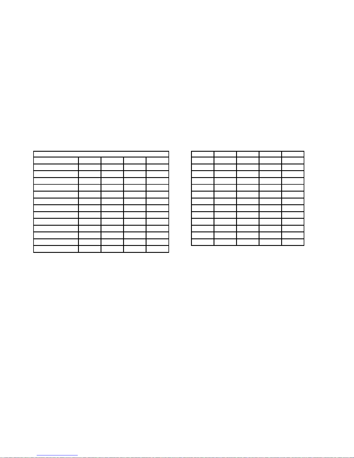
4-25. Rotor
1. To check for excessive wear of rotor (40), measure the
rotor crest-to-crest diameter (See Figure 4-4) and compare with
the following chart:
Rotor
Capacity Standard
*Crest to Crest Dia. (inches)
008 2.772 + .000/—.004
012 2.676 + .000/—.004
022 3.425 + .000/—.004
036 4.015 + .000/—.004
050 4.015 + .000/—.004
065 4.906 + .000/—.004
090 4.906 + .000/—004
115 5.709 + .000/—.004
175 6.584 + .000/—.004
335 5.800 + .000/—.005
345 7.260 + .000/—.004
620 7.128 + .000/—.005
800 7.658 + .000/— .004
* These dimensions are applicable for AAA trim codes only.
NOTE: The rotor is designated by the third, fourth and fifth
numbers in the Model Number, i.e., 2G012G2.
Figure 4-4. Measuring Rotor Dimension
2. If the measured crest-to-crest diameter is within 0.010 inch
of the standard value and is free of deep nicks, gouges, or other
surface defects, the rotor is re-usable.
3. Rotors with crest-to-crest values 0.011 to 0.050 inch under
the standard values should be replaced. These rotors can be

8
returned to Moyno for refurbishing. Rotors are stripped and re-
plated with chrome to standard dimensions provided that:
a. The key slots are not excessively worn.
b. The rotor surface is not cracked, pitted or deeply
grooved (1/32 inch or more).
c. The base surface metal is not pitted or corroded.
4-26. Stator. A worn stator may appear pitted and gouged or
may appear smooth similar to when new. Performance is the
best measure of rotor to stator fit. If unable to measure
performance adequately, suspected stator wear can be
evaluated by a Moyno sales or factory representative.
4-27. All Other Parts. Check for cracks, excessive wear,
damage to threaded holes, burrs, etc. Replace as necessary.
Replace O-rings and all gaskets at each disassembly and
reassembly.
4-28. PUMP ASSEMBLY
(Ref: Table 4-1, Section 4-51)
The Moyno 2000 pumps are reassembled in the reverse order of
dismantling. The following suggestions are offered:
1. While pump isdismantled,check all gaskets,seals,packing,
and O-rings. Replace all worn items. It is recommended that the
gear joint seals (29) and gear joint O-ring (1) be replaced each
time either of the gear joints is disassembled.
During the assembly process, cleanliness is important. To avoid
premature failure, bearings, and gear joint components must be
handled with care and kept clean.
4-29. Lubrication During Assembly
NOTE: The bearings are lubricated at the factory and will only
need to be re-lubricated when the shaft/bearing assembly is
completely removed from pump.
1. Bearings. Pack bearings after installation onshaft (Section
4-32). Lubricant should be packed around all of the rollers and
should completely cover the faces of the races. The void inside
the spacer between the bearings should be filled approximately
half way with lubricant.
2. Gear Joints. Both gear joints should be packed with
lubricant during assembly (Sections 4-34). DO NOT use zerk
fittings to lubricate gear joints after assembly. The pipe plugs (C)
in the drive shaft head, drive shaft, and gear joint shell are vent
plugs and MUST BE REMOVED during assembly of the gear
joints to allow excess lubricant to vent from the gear joints.
3. Packing. Lubricate packing rings during assembly.
Additional grease can be added after assembly through the zerk
fittings installed in the side of the stuffing box.
4. Approved Lubricants.
CAUTION: Do not mix different brands of lubricants for the
same application.
Area to Lubricate Approved Lubricant or Equivalent
Bearings, Gear Joints
& Packing ACG-2
(Dubois Chemical, Inc.)
4-28. Packing Installation
1. The standard packing set (62) consists of five braided
packing rings. Lantern ring halves (7) must be ordered
separately.
2. Install packing and lantern ring halves into the stuffing
box area of the suction housing (35) in the following sequence:
a. Wipe a film of lubricant on each packing ring and
install two rings. Push each ring firmly in place.
NOTE: Install the packing rings with the splits staggered at 90
degrees to the adjacent ring of packing. On initial assembly,
one ring of packing may not fit in stuffing box. This final ring of
packing should be installed after pumpisstarted and packingis
seated.
CAUTION: Always use a proper packing tamper tool to
install packing. Do not use pointed or sharp tool, as
damage to the packing material or drive shaft could result.
To assure proper shaft lubrication, never use a one-piece
spiral wrap packing.
b. Install the two lantern ring halves with the flat side
against the packing.
c. Install final three packing rings, firmly pushing each
ring into place.
3. Installpacking gland studs(6),packinggland halves(28),
and gland adjusting nuts (47). Tighten nuts finger tight at this
time.
4-31. Bearing Housing/Suction Housing Assembly. This
procedure may be performed now or after the bearing drive
shaft assembly is installed in the bearing housing.
1. Place clamp ring (15) on suction housing (35) and install
retaining ring (40) in groove on suction housing.
2. Slide turned diameter of suction housing into bore on end
of bearing housing (34). Align holes in clamp ring (15) with four
threaded holes in bearing housing (34) and thread four hex
head screws (54) with lock washers into threaded holes.
Tighten finger tight.
3. Both suction housing and bearing housing supports should
be hand tightened only to the base. With suction housing and
bearing housing positioned correctly, tighten four hex head
screws (54) to secure suction housing to the bearing housing.
Tighten suction housing and bearing housing feet to the base.
NOTE: Refer to Torque Guidelines Chart (Page 12) for the
proper torque requirement for all threaded fasteners.
4-32. Bearing/Drive Shaft Assembly
1. Bearings must be pressed on the shaft in the following
sequence: (Largerunits [G drive end and larger] require heating of
the bearings to 250 degrees F before assembly).
a. Press bearing (20) cone on shaft (37) making sure
rollersface inproper directiontoreceivecup(Stepb). Cone
should be pressed firmly against shoulder on shaft.
b. Place cup on rollers.
c. Place bearing spacer (22) halves on cup.
d. Place second cup on spacers.
e. Press second bearing (20) cone on shaft with rollers
facing seat in cup. Cone should be pressed on until face of
cone is flush or even with shoulder on shaft.
9
CAUTION: Do not press second cone past shoulder on
shaft.
2.Thread bearing nut (21) on shaft (37) and tighten until it
rests against the shoulder on the drive shaft. Install brass tip
set screw (42) in bearing nut and tighten.
NOTE: The tapered bearings are designed such that when
properly installed there may be a very slight end play in the
bearings (bearing spacer halves mayslip freely outof place) or
they may have a slight pre-load (bearing spacer halves held
tightly in place and bearings do not turn freely).
3.Remove bearing spacer halves (22). Thoroughly pack
lubricant around rollers and on bearing races. Install one half
of bearing spacer. Fill area between bearings half full of
lubricant, and install other half of bearing spacer.
NOTE: Assuming the bearings are not too hot, an alternate
method of lubricating bearings is as follows: Pack the rollersof
the first cone immediately after it is pressed onshaft. Lubricate
race of first cup before it is installed. Place bearing spacer
halves in place and fill it full of lubricant. Lubricate race of
second bearing cup and place on spacer. Pack rollers of
second cone with lubricant, and press on shaft until flush with
shoulder.
NOTE: If too much grease is packed into the bearings during
assembly, it may seep from the grease seals during the first
few hours of operation until the proper lubricant level is
achieved. This lubricant should be wiped from the seal area,
when the pump is not operating, to prevent contaminantsfrom
collecting in the seal area.
4.Install (light press) grease lip seals ( 17 and 18) into bearing
cover plate (30) and bearing housing (34) with Locktite. The lip
of the radial grease seal (18) should be facing outward with
spring visible. The tip of the seal (17) should be facing the
bearings. The lips of both seals should be wiped with grease.
5.Install drive shaft (37) with bearings installed in bearing
housing, being careful to avoid damaging thegrease seal (17).
6.Place O-ring (2) on bearing cover plate (30)and bolt bearing
cover plate to bearing housing (34) using six hex headscrews
(52) and lock washers (56). The six screws should be
tightened evenly, and care should be taken to ensure the O-
ring becomes seated in the step in the bearing housing. When
the bearing cover plate is fully secured to the bearing housing,
a small gap of 0.010 to 0.020 inch will exist between the
bearing cover plate and the bearing housing.
NOTE: Some pumps have a sleeve installed on the drive
shaft to receive any possible wear caused by the packing. If
the shaft sleeve is used, install at this time and tighten set
screws to the drive shaft.
4-33. Rotor/Stator Assembly
1.Slide head ring (25) overrotor (14) contourto the rotorhead.
The side of the head ring with the smallest diameter holes
should be facing the rotor head
NOTE: On some models the head ring is a two-piece com-
ponent which eliminates this step.
2.Slide stator clamp rings (9 and 16) on both ends of the
stator (11) and secure in position with retaining rings (39).
3.Place one stator gasket (4) in recess of adapter flange (27),
and fit adapter flange with gasket to end of stator (11). Install
O-Ring (3) onto adapter flange.
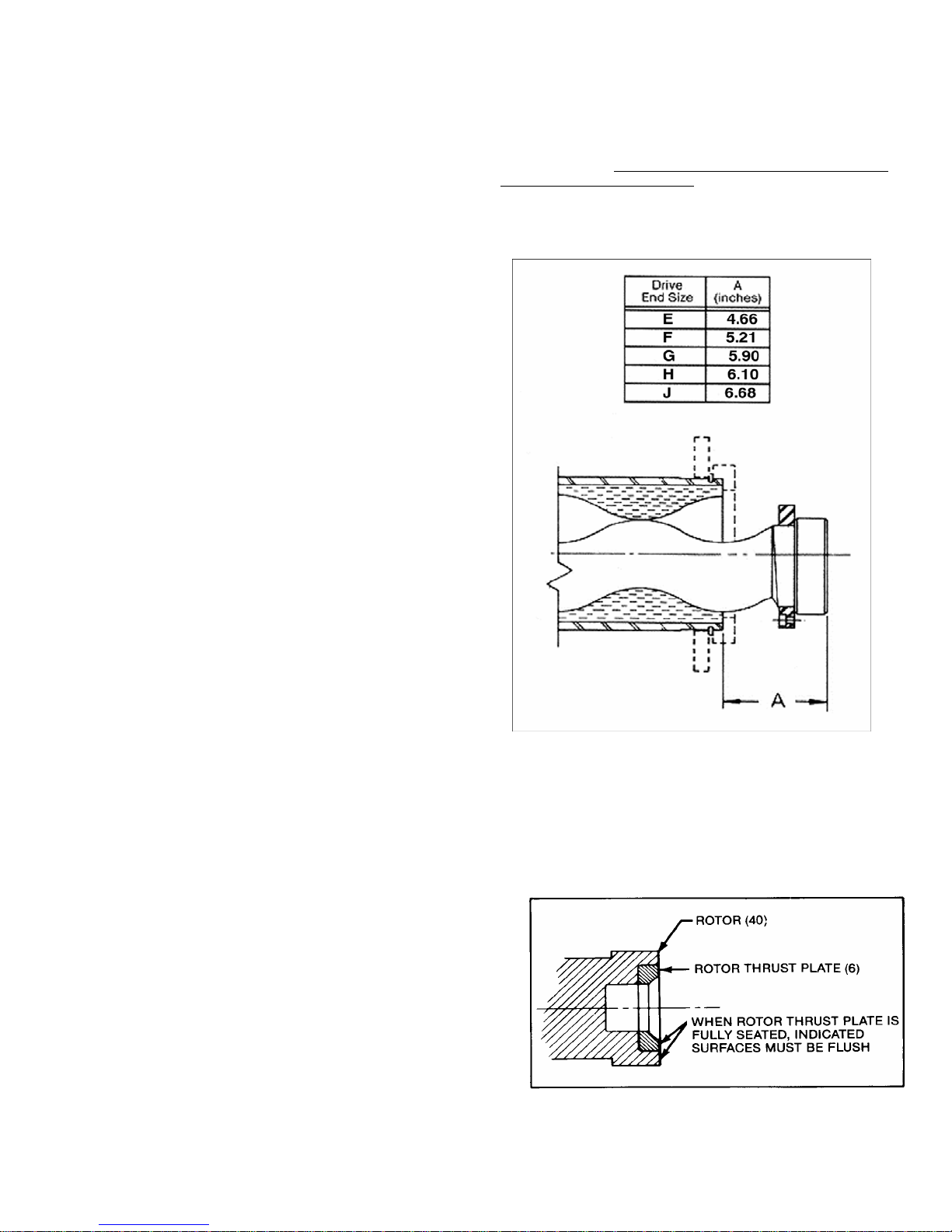
4.Coat the rotor (14) contour with waterless hand cleaner,
glycol, or other lubricant compatible with the stator elastomer.
Insert rotor into stator so that rotor head is at the specified
distance from the end of the stator (Dimension "A," Figure 5-
1). Be sure the rotor is inserted in the end of the stator fitted
with the adapter flange (27) and gasket (4).
NOTE: Rotor can also be inserted in the stator utilizing Moyno’s
Hydraulic Stator Removal Device (SRD). See separate SRD
service manual or contact the local Moyno distributor for further
information on this new product.
NOTE: Turning the rotor counterclockwise while inserting into
stator will ease assembly.
Figure 4-5. Rotor Installation
4-34. Rotor Gear Joint Assembly
1. Slip O-ring (1) over the rotor head and allow to hang loose.
Insert primary thrust plate (23) into rotor head, flat side first.
Thrust plate and rotor head surfaces must be flush to assure
proper assembly and operation of the pump (see Figure 5-2.).
2. Assemble the rotor end gear joint by first fitting a gear joint
seal (29) onto the connecting rod assembly (36). The seal must
be positioned so that the flat face of the seal neck fits into the
Figure 4-6. Rotor Thrust Plate Seating Detail

10
seal retainer component ofthe connectingrodassembly.Applya
small coating of approved gear joint lubricant to the inside
surfaces of the seal.
3. Apply a small amount of lubricant to the flat face of the seal
support (26) and slide it onto the connecting rod so that the flat
face and radius of the support is against the seal (29).
4. Grease theconcavespherical surface of the rear thrust plate
(24) and position thrust plate against the seal (29) with the lipon
the outside diameter of the seal fitting the step on the back side
of the thrust plate.
5. Apply a film of grease to the splines on the inside ofthe gear
ball (12). Install gear ball on connecting rod (36), with counter-
bored end of the gear ball (end without splines) first on
connecting rod. Gear ball should slide freely against shoulder on
connecting rod.Placelock nut (48)onconnecting rod andtighten
against gear ball. Apply grease to sphericalsurfaces and teeth of
gear ball.
6. Apply grease to the teeth of the ring gear (10), and slide ring
gear into the gear ball (12). When ring gear is in place, keyways
should be facing the lock nut end of connecting rod.
7. Apply a thin coating of grease to the spherical surface of the
thrust plate (23) already installed in the rotor head. Fill the
recessed area in the rotor head with grease.
8. Slide the gear joint shell (31) over the connecting rod (36)
and assembled gear joint components, being careful to seat the
outside diameter of the gear joint seal (29) in the end of the gear
joint shell (31). The two tapped holes in the gear joint shell
should be in line with one of the keyways in the ring gear.
9.
Place keys (5) in the keyways in the ring gear (10). Check
to ensure the
tapped holes in the side of the gear joint shell (31) are
aligned with one of the keyways.
10. Align the keys (5) in the ring gear (10) with the keyways in
the rotor head (14). Slide assembled gear joint shell (31) onto
the rotor head, checking to be sure the keys are properly
engaged in the rotor head and ring gear. The shallow hole in the
rotor head should be aligned with the first threaded hole in the
outside of the gear joint shell. Thread the set screw (41) into the
threaded hole in the shell until light contact is made with thehole
in the rotor head.
11. Place O-ring (1) into step in gear joint shell. Align holes in
head ring (25) with six threaded holes in end of gear joint shell
(31) and install stainless socket head screws (50) and lock
washer (58). Tighten the six socket head screws evenly,
checking to ensure O-ring (1) remains in place. When tightened
properly, a small gap of a few thousandths of an inch may exist
between the shell (31) and head ring (25).
12. Excess grease in the assembly will be purged from the vent
hole while the socket head screws (50) are tightened. Tighten
the set screw (41) in the shell (31). Move the free end of the
connecting rod (36) in a circular motion to assure that the joint is
free and assembled properly. This will also help to purge excess
grease from the assembly.
13. Install the stainless steel pipe plug (45) in the second hole in
the shell and tighten.
14. Assemble the back gear joint between the conrod (36) and
the intermediate drive shaft (38) in a similar fashion.
4-35. Rotor/Stator to Drive End Assembly
1. If not already in place, slip stator clamp rings (16 and 9) on
both ends of stator (11), and install retaining rings (39) in
grooves provided on both ends of stator.
2. Place stator gasket (4) in recess in end of adapter flange
(27) and discharge flange (9). Install O-Ring (3) onto adapter
flange.
3. Apply generous amount of anti-seize to male portion of
the drive shaft (37) that the intermediate shaft (38) will cover.
4. Move the rotor/stator, connecting rod, and intermediate
shaft assembly in position, and insert intermediate shaft (38)
through the suction housing (35) and its stuffing box while
sliding over the drive shaft (37). The assembly should be
supported as it is threaded through the suction housing. Align
stator (11) andadapter flange(27)withbore in suctionhousing,
and slide adapter flange in place, checking to ensure that O-
ring (3) remains properly positioned.
5. Rotate stator (11) until the hole on the intermediate shaft
(38) lines up with the matinghole on the drive shaft (37). When
holes are aligned, insert shaft pin (19) through both shafts. To
secure, position the two halves of the shaft collar (33) over the
shaft pin and tighten down with the shaft collar screws (49).
NOTE: To help align the pin holes once the intermediate shaft
(38) is positioned over the drive shaft (37), tap the end of the
rotor with a block of wood to help position the drive train.
6. Align holes in clamp ring (16) with threaded holes in
suction housing, and thread four hex head screws (64) with
lock washers (65) through holes in clamp ring into threaded
holes in suction housing. Tighten hex head screws evenly.
7. Make sure packing (62), lantern rings (7), and packing
glands (28) are positioned correctly. Tighten packing nut (47) a
little more than finger tight.
4-36. Stator Support/Discharge Assembly
1. Place top of stator support(s) (13) over stator and fasten
to bottom half of stator supports using hex head screws (55).
2. If not already done so, place stator gasket (4)inrecessin
discharge flange (8) and position discharge flange on end of
stator. Align holes in stator clamp ring (9) with threaded holes
in discharge flange, and install and tighten hex head screws
(53) and washers (57).
4-37. G3 BRIDGE BREAKER ASSEMBLY
The bridge breaker is reassembled in the reverse order of
dismantling.
Reference Table 4-2 Parts List and the G3 Exploded View
in addition to the G2 parts.
4-38.
G3 Drive Side Assembly
1. Insert the paddle drive shafts (10) and the paddle
intermediate shaft (9) from the inside of the suction housing
(13) and through their respective stuffing box bores. Insert the
packing rings (1) into the stuffing box bores on the suction
housing (13). Lantern rings are not normally used onthe bridge
breaker assembly. Thread in the packing gland studs (22) to
the suction housing.

11
2. Insert spring dowels (27) into the extension block (6).
Dowel pins align the extension block to the suction housing
(13) and align the extension block to the gearcase (16). Insert
extension block (6) into the suction housing (13) through the
use of the spring dowels.
3. Insert grease seals (21) into gearcase (16) bore. Install
bearings (4) also into the gearcase bore andsecure in position
with the snap ring retainers (20). Bearings on the G3 bridge
breaker are the sealed bearing type and do not require grease
themselves.
4. Insert seal washer (38) onto socket screws (29).
5. Support gearcase (16) for installation. Position gearcase
over the paddle drive shaft (10) and intermediate drive shaft
(9), and position so spring dowels (27) are engaged in the
gearcase. Tap lightly with a rubber mallet to ensure proper
engagement.
6. Screw socket screws (29) through the gearcase(16),
both sets of dowel pins(27), extension block (6), and thread
into the suction housing (13). Gearcase is also supported from
the suction housing. Insertscrew(30) through washer(67) and
suction housing (13) support bracket, and tighten into the
gearcase.
7. Position heads of the paddle drive shafts (10) and the
paddle intermediate shaft (9) approximately 0.125” from the
inside of the suction housing (13). Lock down the bearing (4)
to the shafts by tightening the bearing set screw.
8. Position key (23) into the keyway on the paddle drive
shaft (10). Lubricate gears (5) with bearing grease and slide
gear over the drive shaft and position on the key inside of the
gearcase (16). Turn the paddle drive shaft (10) and paddle
intermediate shaft (9) so the exposed clamp collar portion in
the suction housing (13) is facing up. Install key (23) and gear
(5) on the intermediate paddle drive shaft (9) in a similar way.
Position so teeth of the gears are intermeshing.
9. Insert grease seal (21) into the gear case cover (17).
Install drive adapter (15) onto the gear case cover (17) by
securing hex screw (33) and washer (65). Position the gear
case gasket (7) on the gearcase cover.
10. Install the gearcase cover (17) over the paddle drive
shaft (10) ensuring the grease seal (21) and gasket (7) is
properly positioned. Secure with hex screws (31 and 66) and
washers (65).
11. Align the key way of the gearmotor (39) with the keyway
of the paddle drive shaft (10). Gearmotor shaft can be rotated
by spinning the motor fan. Support gearmotor (39) for
installation and insert key (24) on to the paddle drive shaft
(10). Slide the gearmotor over the paddle drive shaft until the
gearmotor flange meets up with the drive adapter (15). Secure
gearmotor with the hex bolts (35) and washers (66) to the
drive adapter (15).
NOTE: Certain models may use a belt and pulley arrangement
with a shaft output gearmotor instead of a hollow shaft
gearmotor. On these models, an adapter flange is substituted
for the drive adapter (15). A pulley would be installed on the
paddle drive shaft (10) instead of the hollow shaft gearmotor.
4-39. G3 Bearing Side Assembly
1.Insert the paddle end shafts (12) from the inside of the
suction housing (13) and through their respective stuffing box
bores. Insert the packing rings (1) into the stuffing box bores
on the suction housing (13). Lantern rings are not normally
used on the bridge breaker assembly. Thread in the packing
gland studs (22) to the suction housing.
2. Insert spring dowels (27) into the extension block (6). Dowel
pins align the extension block to the suction housing (13) and
align the extension block to the bearing retainer (11). Insert
extension block (6) into the suction housing (13) through the
use of the spring dowels.
Install bearings (4) into the bearing retainer bore and secure in
position with the snap ring retainers (20). Bearings on the G3
bridge breaker are the sealed bearing type and do not require
grease themselves.
3. Insert washer (63) onto hex screws (32).
4. Support bearing retainer (11) for installation. Position
bearing retainer over the paddle end shaft (12) and position so
spring dowels (27) are engaged in the bearing retainer. Tap
lightly with a rubber mallet to ensure proper engagement.
5. Screw socket screws (32) through the bearing retainer (11),
both sets of dowel pins(27), extension block (6), and thread into
the suction housing (13).
4-40. G3 Paddle Assembly
1. Rotate paddledriveshaft(10), paddleintermediateshaft(9),
and paddle end shafts (12) with open collar half up. Insert
paddles into each shaft. It may be necessaryto movepaddleend
shafts (12) along their axis to position the bridge breaker drive
train.
2. Use Locktite 242 medium strength threadlockercompound
on the socket screws (28). Place shaft collar on paddleshaft and
secure with socket screws (28). Torque socket screws to 190 in.
lbs of torque on the E, F, and G drive ends and 345 in. lbs of
torque on the H, J, and K drive ends. Torque down screws using
a cross over sequence so coupling half is evenly spaced on
paddles and not slanted towards one side.
Note: Do not operate paddles without using a thread locker
compound on the socket screws and torquing the screws to
their proper level.
3. On the bearing side assembly, lock down the bearing (4) to
the paddle end shafts (12) by tightening the bearing set screw.
4. In two meter suction housing lengths, there is an additional
hanger bracket which will also need to be installed afterpaddles
are positioned. To install the bracket for each paddle, position
hanger bushing (79) around paddle end shaft (12). Position
bushing bracket (74) around bushings (79) and secure with hex
screw (80), washer (77) and hex nuts (78). Locate the bushing
bracket (74), in comparison to the suction housing (13), through
the use of bushing shims (73). Attach bushing bracket (74)to the
suction housing with hex screw (75) and washer (76).

12
4-4.FINAL ASSEMBLY
1. Install pipe plugs (43) and zerk fittings (63) in appropriate
threaded holes in suction housing. Install pipe plugs in threaded
holes ofthebearinghousing catchbasinunder the exposeddrive
shaft, or attach drain lines if preferred.
2. Position packing gland halves (8) around each shaft and
tighten packing hex nut (26) to slightly more than finger tight.
3. Install shaft guard (18 and 19) by securing hex nut (25) and
washers (36 and 37).
4. Connect power source. Turn on flush water to packing if
used. Open suction and discharge valves, and start pump.
4-42. Packing Adjustment
After starting, adjust packing per Section 4-3.
4-43. OTHER CONSIDERATIONS
4-44. Short-Term Storage. Storage of 6 months or less will not
damage the pump. However, to ensure the best possible
protection, the following is advised:
1. Store pump inside whenever possible or cover with some
type of protective covering. Do not allow moisture to collect
around pump.
2. Remove drain plug and inspection plates to allow the pump
body to drain and dry completely. Replace inspection plates.
3. Loosen the packing gland and inject a liberal amount of
grease into the stuffing box. Tighten the gland nuts only hand
tight. When water flush systems are to be used, do not use
grease. A small amount of light oil is recommended.
4. See drive manufacturer's instructions for motor and/or drive
storage.
5. See OPERATION Sections 3-1 through 3-4 before startup.
Be sure all lubricants are in good condition.
4-45. Long-Term Storage. If pump is to be in storage for more
than 6 months,performthe above short-termstorageprocedures
plus the following:
1. Occasionally rotate thepump manuallya few revolutionsto
avoid a "set" condition of rotor in stator elastomer. This will
prevent hard starting and excessive torque requirements when
pump is again put into operation.
2. Apply rust inhibitor to all unpainted cast iron and machined
carbon steel surfaces.
3. Remove drive belts if applicable.
4-46. PACKING SPECIFICATION
Standard packing on all Moyno 2000 pumps consists of braided
PTFE fibers impregnated with ultra-fine graphite. Optional types
of packing are available for food, high temperature, and other
types of service. Consult your nearest Moyno representative.
4-47. VARIATIONS OF STANDARD PARTS
The following are variations available for modifying pumps to
meet specialized pumping conditions. If the trim code of your
pump is other than "AAA", contact your nearest Moyno
representative for clarification. Do not modify your pump with
any variation unless you have determined that it is compatible
with your application.
The three-character trim code is designed as follows. The first
character identifies any seal variations, the second character
identifies any internal variations, and the third character
identifies any rotor variations.
Sealing
Variation
Internal
Variation
Rotor
Variation
A A A
The trim code"AAA"represents a pumpwithstandardfeatures.
Deviations from standard are to be indicated by changing the
appropriate character from the choices listed. When two or
more letters are combined, dashes are used to separate the
three areas of the trim code for clarify.
SEALING VARIATIONS
A ⎯BRAIDED TEFLON & GRAPHITE PACKING (Black).
Standard to all lines except Quick Disassembly pumps.
Optional on Quick Disassembly pumps.
C ⎯BRAIDED TEFLON PACKING (White). Optional packing
on all lines.
D ⎯DOUBLE MECHANICAL SEAL. Optional on all lines; not
offered on #2 "L" Frame.
F ⎯BRAIDED TEFLON FOOD GRADE PACKING (White).
Standard on all Quick Disassembly pumps. Optional on
all other lines.
G ⎯100% GRAPHITE PACKING (Gray). Optional to all lines.
H ⎯FLUSH PACKING GLAND.
S ⎯SINGLE MECHANICAL SEAL. Optional on all lines.
W ⎯WATER FLUSH. Optional on all lines.
X ⎯Special to application
INTERNAL VARIATIONS
A ⎯Standard plated shaft.
B ⎯Non--plated shaft.
C ⎯Solid drive shaft configuration.
E ⎯Extension tube with auger (Standard on G2/G3 version 5)
F ⎯Extended drive shaft (for back stop or large pulley).
G ⎯RMP15 ceramic coated drive shaft.
K ⎯RMS20 carbide coated drive shaft
M ⎯RMD10 carbide coated drive shaft.
R ⎯Fiber deflector
S ⎯Shaft sleeve
X ⎯Special to application.
ROTOR VARIATIONS
A ⎯Standard size with chrome plating.
B ⎯Non-plated (no plating).
13
C ⎯Standard undersize.
E ⎯Standard oversize.
G ⎯RMP15 ceramic coating.
K ⎯RMS20 carbide coating.
M ⎯RMD10 carbide coating.
X ⎯Special to application.
4-48. Rotors identified on parts listing are standard size with
hard chrome plated surface. Other variations of rotor size and
finish may be ordered by selecting the standard rotor part
number and changing the last digit of the rotor number as
follows:
2 = Standard size, non-plated.
3 = Undersize, chrome plated.
4 = Undersize, non-plated.
5 = Oversize, chrome plated.
Do not change rotor sizes without consulting your local Moyno
sales office. These variations are used for certain specialized
pumping conditions only.
4-49. Drive shafts shown have hard chrome plating on the
packing wear area. If non-plated drive shafts are required,
consult factory.
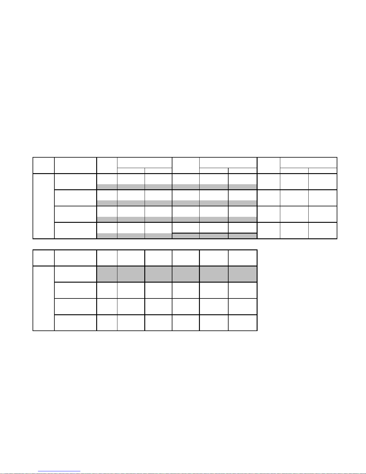
TORQUE GUIDELINES CHART
Stainless Steel Bolts Carbon Steel Bolts
Size Max. Torque Size Max Torque
NO. 10-24 22.8 in. lb. 5/16-18 10 ft. lb.
1/4-20 75.2 in lb. 3-/8-16 21.7 ft. lb.
5/16 - 18 132 in. lb. 1/2 - 13 43.5 ft. lb.
3/8 - 16 236 in. lb. 5/8 - 11 86 ft. lb.
1/2 - 13 517 in. lb. 3/4 - 10 152 ft. lb.
Connecting Rod Lock Nuts
Drive End Nut Size Max. Torque
F 3/4 - 16 35 ft. lb.
G, H 7/8 - 14 50 ft. lb.
J 1-1/4 - 12 85 ft. lb.
K 1-1/2 - 12 110 ft. lb.
NOTE: Torque values are from the Industrial Fasteners Institute
and Craftsman Corp.
4-50. SELECTING THE CORRECT PART FOR YOUR MOYNO 2000 PROGRESSING CAVITY PUMP
NOTE: For “Hopper types” other than “M”, Type / Trim codes designated by “X”, specialty stator materials not
shown, and specialty materials like stainless steel or hastelloy, consult factory for updated parts listing per the
pumps “AS” serial number.
14
4-51. G2 Open Throat Parts List
1 O-Ring : Rotor/intermed Sft 3207902150 3207902153 3207902156 3207902158 3207902162 3207902264
2 O-Ring - Bearing Cover 3207902248 3207902256 3207902264 3207902267 3207902270 3207902450
3 O-Ring : Adapter Flange 3207902251 3207902258 3207902262 3207902269 3207902275 3207902278
4 Stator Gasket 4052001000 4062000900 4072001000 4082000900 4082000900 4102001300
5 Key - Gear Joint 4052001100 4062001000 4072001100 4082001000 4092000700 4102000800
6 Gland Studs 4052001400 4052001400 4072001400 4092000900 4092000900 4220022000
7 Latern Ring Half 4053000500 4230011000 4230042000 4230057000 4093000500 4230068000
8 Discharge Flange 4053000901 4063001001 4073000901 4083000901 4083000901 4103004301
9 Clamp Ring - Disch Flange 4053001000 4063001100 4073001000 4083001000 4083001000 4103004200
10 Ring Gear 4053001200 4064000900 4074000900 4084000900 4094000900 4104000900
11 Stator
12 Gear Joint Ball 4054000700 4064000700 4074000700 4084000700 4094000700 4104000700
13 Stator Support 4054000901 4064001001 4074001000 4084001000 4094001300 4104001001
14 Rotor
15 Clamp Ring 4063001100 4073001000 4230052000 4083001000 4230017000 4230070000
16 Clamp Ring - Suction Housing 4063002200 4073001800 4230855000 4230856000 4103002200 4230879000
17 Grease Seal - Bearing Housing 4220045000 4102009800 4220014000 4220016001 3201693000 4220019000
18 Grease Seal - Bearing Cover 4102000600 4102009800 4220014000 4220016000 3201693000 4220050000
19 Drive Pin 4220769017 4220770017 4220771017 4220772017 4220773017 4220774017
20 Roller Bearing 4230029000 4230007000 4230046000 4230054000 4230013000 4230073000
21 Bearing Lock Nut 4230030000 4240015000 4240065000 4240075000 4240023000 4240082000
22 Bearing Spacer 4230031000 4230008000 4230047000 4230053000 4230014000 4230071000
23 Thrust Plate 4230037000 4230027000 4230044000 4230061000 4230028000 4230065000
24 Thrust Plate Rear 4230038000 4230003000 4230045000 4230062000 4240019000 4230066000
25 Head Ring 4230039001 4230010001 4240070001 4240074001 4240021001 4240085001
26 Seal support -Gear Joint 4230040000 4220001000 4230051000 4230059000 4230016000 4230072000
27 Adapter Flange 4230850001 4230851001 4230852001 4230853001 4230854001 4241496001
28 Packing Gland Half 4240008001 4240006001 4240009001 4240013001 4240012001 4240026001
29 Gear Joint Seal 4240055001 4230006001 4240071001 4230060001 4240020001 4240079001
30 Bearing Cover Plate 4240059000 4240005000 4240069000 4240086000 4240011000 4240025000
31 Gear Joint Shell 4240060004 4240007004 4240067004 4240073004 4240022004 4240084004
32 Support 4241575001 4241576001 4241577001 4241578001 4241578001 4241579001
33 Shaft Collar 4241609001 4241609002 4241609003 4241609004 4241609005 4241609006
34 Bearing Housing 4250010000 4250003000 4250014000 4250019000 4250005000 4250023000
ITEM # G2 PART DESCRIPTION E PART
NUMBER F PART
NUMBER G PART
NUMBER H PART
NUMBER J PART
NUMBER K PART
NUMBER
See Rotor Chart
See Stator Chart

15
G2 Open Throat Parts List (continued)
G2 Suction Housing - Std CS 4251554001 4251534001 4251491001 NA NA NA
G2 Suction Housing - 1meter CS 4251555001 4251535001 4251492001 4251542001 4251503001 4251566001
G2 Suction Housing - 1.5 meter CS 4251556001 4251536001 4251493001 4251543001 4251504001 4251567001
G2 Suction Housing - 2 meter CS 4251557001 4251537001 4251494001 4251544001 4251505001 4251568001
36 Auger connecting rod - Std CS
37 Drive Shaft 4251639001 4251640001 4251641001 4251642001 4251643001 4251644001
38 Intermediate Drive Shaft 4251645001 4251646001 4251647001 4251648001 4251649001 4251650001
39 Retainer Ring - Stator 4052000200 4062000200 4072000400 4082000600 4082000600 4102001200
40 Retainer Ring - Bearing Housing 4062000200 4072000400 4220015000 4082000600 4220006000 4220021000
41 Set Screw - Gear Joint shell 4220052001 4220052001 4220052001 4220052001 4220052002 4220052002
42 Set Screw - Bearing Lock Nut 4220053000 4220053000 4220053000 4220053000 4220053000 4220053000
43 Pipe Plug - Suction Housing 6100030160 6100030160 6100030160 6100030160 6100030160 6100030160
44 Pipe Plug - Bearing Housing 4220485000 4220485000 4220485000 4220485000 4220485000 4220485000
45 Socket Pipe Plug - Gear Joint Shell 4220044001 4220044001 4220044001 4220044001 4220044001 4220044001
46 Key - Drive Shaft 6110080600 6110080600 6110100640 6110120680 6110140680 6110160800
47 Hex Nuts - Packing Gland 6140010111 6140010111 6140050051 6140050071 6140050071 6140050081
48 Lock Nut 4052006401 4052006402 4052006403 4052006403 4052006404 4052006405
49 Hex Screw - Shaft Collar
50 Socket Screw - Head Ring 6191432080 6191442120 6191442120 6191452140 6191462200 6191482200
51 Hex Screw- Support 6191530201 6191530201 6191530201 6191550241 6191550241 6191550241
52 Hex Screw- Bearing Cover 6191530281 6191550281 6191550321 6191570361 6191570361 6191580441
53 Hex Screw - Disch Flange 6191570241 6191570241 6191580281 6191580321 6191580321 6191580361
54 Hex Scew - Bearing Housing 6191570321 6191580321 6191580321 6191580361 6191580361 6191580401
55 Hex Bolt - Stator support 6191570521 6191570481 6191580561 6191580561 6191580721 6191570641
56 Lock Washer - Bearing Cover 6230010411 6230010431 6230010431 6230010451 6230010451 6230010471
57 Lock Washer - Disch Flange 6230010451 6230010451 6230010471 6230010471 6230010471 6230010471
58 Lock Washer - Head ring 6230012970 6230012990 6230012990 6230013000 6230013010 6230013030
59 Lock washer - Bearing Housing 6230010451 6230010471 6230010471 6230010471 6230010471 6230010471
60 Hex Nut- Support 6140010111 6140010111 6140010111 6140050051 6140050051 6140050051
61 Lock Washer - Support 6230010411 6230010411 6230010411 6230010431 6230010431 6230010431
62 Packing set 3403396016 3403396019 3403396021 3403396024 3403396026 3403396028
63 Grease Fitting - Stuffing Box 3207259001 3207259001 3207259001 3207259001 3207259001 3207259001
63 Pipe Plug - Stuffing Box 6100120011 6100120011 6100120011 6100120011 6100120011 6100120011
64 Hex Screw - Suction Housing 6191570321 6191580361 6191580401 6191580401 6191580441 6191580441
65 Lock Washer - Suction Housing 6230010451 6230010471 6230010471 6230010471 6230010471 6230010471
35
ITEM # G2 PART DESCRIPTION E PART
NUMBER F PART
NUMBER G PART
NUMBER K PART
NUMBER
H PART
NUMBER J PART
NUMBER
See Connecting Rod Chart
Part of Shaft Collar assembly - Item 33
16
G2 Open Throat Parts List (continued)
Rotor (Ref. No. 14) for Type Designations Beginning with CD Stator (Ref. No. 11) Part Number
MODEL1246
1246 F012 CD310E
†
CD320E
†
CD340E
†
CD360E
†
C71FE1 C72FE1 C74FE1 C76FE1 F022 CD310F
†
CD320F
†
CD340F
†
----
C71FF1 C72FF1 C74FF1 ----- G022 ---- ---- ---- CD360F
†
----- ----- ----- C76GF1 G036 CD310G
†
CD320G
†
CD340G
†
----
C71GG1 C72GG1 C74GG1 ----- G050 CD3150
†
CD3250
†
CD3450
†
----
C71G51 C72G51 C74G51 ----- H036 ---- ---- ---- CD360G
†
----- ----- ----- C76HG1 H050 ---- ---- ---- CD3650
†
----- ----- ----- C76H51 H065 CD310H
†
CD320H
†
CD340H
†
----
C71HH1 C72HH1 C74HH1 ----- H090 ---- CD3290
†
CD3490
†
----
C71H91 C72H91 C74H91 ----- J065 ---- ---- ---- CD360H
†
----- ----- ----- C76JH1 J090 ---- ---- ---- CD3690
†
----- ----- ----- C76J91 J115 CD310JH
†
CD320J
†
CD340J
†
----
C71JJ1 C72JJ1 C74JJ1 ----- K115 ---- ---- ---- CD360J
†
----- ----- ----- C76KJ1
STAGES
MODEL
F012
F022
G022
G036
G050
H036
H050
H065
H090
J065
J090
J115
K115 † Add third letter of Type Designation to complete the
part number; i.e., for Type CDQ, add Q to basic number
of stator.
17
G2 Open Throat Parts List (continued)
Connecting Rod Chart (Ref # 36)
G2 G3 G2 G3 G2 G3
008 4251737001 4251737301 012 4251739001 4251739301 022 4251741001 4251741301
012 4251609001 4251609301 022 4251610001 4251610301 036 4251611001 4251611301
050 4251743001 4251743301
008 4251737101 4251737401 012 4251739101 4251739401 022 4251741101 4251741401
012 4251609101 4251609401 022 4251610101 4251610401 036 4251611101 4251611401
050 4251743101 4251743401
008 4251737201 4251738101 012 4251739201 4251740101 022 4251741201 4251742101
012 4251609201 4251615101 022 4251610201 4251616101 036 4251611201 4251617101
050 4251743201 4251744101
008 4251738001 4251738201 012 4251740001 4251740201 022 4251742001 4251742201
012 4251615001 4251615201 022 4251616001 4251616201 036 4251617001 4251617201
050 4251744001 4251744201
036 4251541001 090 4251758001
065 4251612001 115 4251613001 175 4251614001
090 4251573001 175 4251760001
036 4251572001 090 4251759001
065 4251618001 115 4251619001 175 4251620001
090 4251574001 175 4251761001
036 4251572101 090 4251759101
065 4251618101 115 4251619101 175 4251620101
090 4251574101 175 4251761101
Element Size K PART
NUMBER
G PART NUMBER
Element
Size
Element
Size H PART
NUMBER Element
Size J PART
NUMBER
ITEM # G2 PART
DESCRIPTION
36
Conrod Assembly -
STD CS
Conrod Assembly - 1
meter CS
Conrod Assembly -
1.5 meter CS
Conrod Assembly -
2.0 meter CS
36
Conrod Assembly -
STD CS
Conrod Assembly - 1
meter CS
Conrod Assembly -
1.5 meter CS
Conrod Assembly -
2.0 meter CS
Element
Size F PART NUMBER
ITEM # G2 PART
DESCRIPTION Element
Size E PART NUMBER
Other manuals for 2000
1
Table of contents
Other moyno Water Pump manuals


Popular Water Pump manuals by other brands


Daikin
Daikin SUT Series Operation manual

STM
STM DITI1701033 user manual

PSG Dover
PSG Dover All-Flo S050 Installation operation & maintenance

Endress
Endress EMP 205 Translation of the original operating manual

ANDO Technik
ANDO Technik Dosatron D 25 F owner's manual

SUMMER WAVES
SUMMER WAVES RX1000 owner's manual