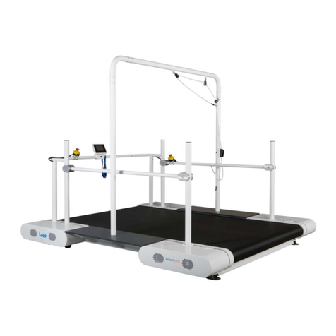
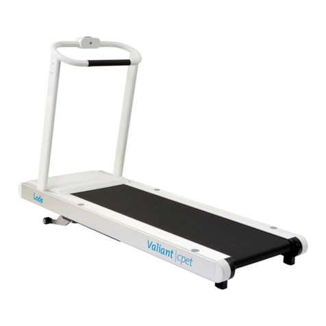
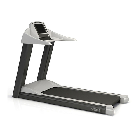
Lode OEM User manual

Service manual
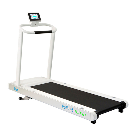
OEM TREADMILL
ERGOMETERS
0344

Service manual OEM treadmill V2.03
Intended Use
A Lode treadmill is a diagnostic tool intended to be used as a stress test device in a medical
environment. The main goal of the use of a Lode treadmill is to create reproducible stress
tests. The following parameters can be measured:
•Speed (km/h or Miles/h)
•Time (minutes and seconds)
•Distance (km Miles Meters)
•Optional: Heart rate (beats per minute)
•Grade (%)
In combination with other diagnostic tools, like ECG or pulmonary function equipment, other
important physiological data can be obtained, allowing a physician to evaluate a test subject’s
physical status.
A Lode treadmill is designed both for manual operation and control by external ECG-,
pulmonary equipment. In combination with optional software, the ergometer can also be
controlled by a PC.
The Lode treadmill has to be operated under the supervision of well-trained medical specialists,
like cardiologists, pulmonologists and physiotherapists. The ultimate judgment whether a test
subject should undertake a stress test with an ergometer and which protocols should be used
must be made by the responsible medical specialist, based on the limitations of each
individual, the medical history and all other applicable circumstances. Neither Lode BV nor her
distributors take any responsibility for the final use of its equipment.
Contra Indication
The Lode treadmills are to be operated by classified personnel only. As stated in the
intended use, the Lode treadmills are intended to be used in a medical environment. During the
intended use the test subject will deliver energy. Application of the wrong dosis of energy
could lead to permanent damage of the test subject’s health.
Maintenance
The Lode treadmills should be calibrated once a year. In case any damage is observed of the
Lode treadmill. Lode B.V. or her representative should be informed in order to execute the
necessary repair(s). Service of the Lode treadmills is restricted to factory-trained personnel
only.
Precautions
Caution: This device should only be sold by, or on the order of authorized persons.
Caution: Not suitable for use in the presence of flammable anaesthetics.
Possible hazards
Using the Lode treadmills according to intended use, contra indications, maintenance,
precaution and common sense stated above may not eliminate all hazards. Possible residual
hazards could be: wrong installation, wrong use, wrong dose, wrong interpretation of
readings, mechanical breakdown of parts, software failure.

Service manual OEM treadmill V2.03
List of Symbols used
On/Off switch
External Input
External Output
Type B Electrical Safety
Separate collection of electric and electronic equipment
Copyright Lode BV, February 2012, all rights reserved.
Manufacturer information:
Lode BV
Zernikepark 16
NL-9747 AN Groningen,
The Netherlands
℡
: +31 50 571 28 11
: +31 50 57167 46
@
:
www.lode.nl

Service manual OEM treadmill V2.03
Warnings
Observe the following precautions when servicing the treadmill:
•Do not start the walking belt when someone is on the treadmill. The belt could start
moving immediately, and sudden start and subsequent loss of balance could cause
serious personal injury.
•High voltage is present when the treadmill hood is removed and the treadmill is
plugged in.
•Do not wear loose clothing around the rotating machinery.
•Never place your fingers near rotating parts.

Service manual OEM treadmill V2.03
Tabel of contents
1
TECHNICAL SPECIFICATIONS ............................................................................................................ 6
1.1
T
ECHNICAL SPECIFICATIONS
OEM
TREADMILL
939900 ............................................................................ 7
2
ASSEMBLIES ............................................................................................................................................. 9
2.1
F
INAL ASSEMBLY
OEM
TREADMILL
939900 ........................................................................................... 10
2.2
H
ANDRAIL ASSY
939020 ......................................................................................................................... 11
2.3
U
PPER HANDRAIL ASSY
939110............................................................................................................... 12
2.4
M
OTOR COMPARTMENT
9394502
1/8/11 .............................................................................................. 13
2.5
B
ELT
&
DECK
932950
&
939951 ............................................................................................................. 14
2.6
D
RIVE AND REVERSE ROLLERS
1/8/11 ................................................................................................. 15
2.7
G
RADE MOTOR
220017............................................................................................................................ 16
2.8
M
OTOR COMPARTMENT
9394503
1/8/11 .............................................................................................. 17
2.9
G
RADE ADJUSTMENT ASSY
...................................................................................................................... 21
3
PROCEDURES...........................................................................................................................................22
3.1
F
IXATION AND REMOVAL OF THE HANDLEBAR
........................................................................................ 23
3.2
R
EMOVAL OF THE COVER MOTOR COMPARTMENT
................................................................................... 25
3.3
R
EPLACEMENT
C
OMMUNICATION INTERFACE MODULE
(CIM)................................................................ 26
3.4
R
EPLACEMENT INSTRUCTION GRADE MOTOR
220017.............................................................................. 27
3.5
R
EPLACEMENT INSTRUCTION MAIN BOARD
945701................................................................................. 29
3.6
R
EPLACEMENT INSTRUCTION BELT
&
DECK
............................................................................................ 32
3.7
USB
DRIVER INSTALLATION
.................................................................................................................... 38
3.8
T
ERMINAL APPLICATION MENU
............................................................................................................... 39
3.9
S
ELECTING COMMUNICATION PROTOCOL
................................................................................................ 41
4
SCHEMATICS AND LAY-OUTS ............................................................................................................46
5
TROUBLE SHOOTING............................................................................................................................50
5.1
M
ESSAGES
............................................................................................................................................... 51
6
MAINTENANCE .......................................................................................................................................54
6.1
G
ENERAL
M
AINTENANCE
........................................................................................................................ 55
6.2
S
PEED CALIBRATION
................................................................................................................................ 56
6.3
G
RADE CALIBRATION
.............................................................................................................................. 57
6.4
W
ALKING BELT TENSION
......................................................................................................................... 58
6.5
W
ALKING BELT ALIGNMENT
.................................................................................................................... 59
6.6
M
OTOR BELT TENSION
............................................................................................................................. 60
6.7
I
NCLINATION SYSTEM
.............................................................................................................................. 61
6.8
E
MBEDDED SOFTWARE
CIM
AND
TCM................................................................................................... 62
Service manual OEM treadmill V2.03 6
1 Technical specifications

Service manual OEM treadmill V2.03 7
1.1 Technical specifications OEM treadmill 939900
LODE TREADMILL OEM Treadmill 939900
SPEED RANGE
- km/h 0,5 – 20 km/h (steps 0,1 km/h)
- mph 0.3 – 12 mph
HEIGHT ADJUSTMENT FRONT SIDE 0 – 25%
WALKING SURFACE
50 x 150 cm
MAXIMUM PATIENT WEIGHT 160 kg
POWER REQUIREMENTS 230 VAC, 50-60 Hz
115 VAC, 50-60 Hz. (Between two Phases)
- Motor 1,8 kW
DIMENSIONS (L x B x H), cm 212 x 76 x 110 cm
WEIGHT 145 kg
ENVIRONMENTAL CONDITIONS
Operational:
- temperature ºC (ºF) 14 – 40 ºC (57 – 104 ºF)
- humidity ( non condensing) % 30 - 90
- air pressure kPa 70 - 106
Storage:
- temperature ºC (ºF) -25 - 70ºC (13 – 167 ºF)
- humidity ( non condensing) % 10 - 95
- air pressure kPa 50 - 106
STANDARD & SAFETY NORMS ISO 9001:2000, ISO 13485:2003, IEC 601-1
FDA 510K
SAFETY / EMERGENCY STOP
- magnetic lanyard standard
- stop button optional
INTERFACE RS232, USB
Bluetooth ® and Wifi optional
HEARTRATE optional
REAR ELEVATION
- mechanically: –10% – 0% optional
- electrically: -10% - 0% optional

Service manual OEM treadmill V2.03 8
LODE TREADMILL OEM Treadmill 939900
ENTRANCE PLATE optional
ANTI SLIP STRIPS standard
SIDE HANDRAILS FIXED (HEIGHT 850 MM) optional
SIDE HANDRAILS ADJUSTABLE optional
- height: 791 – 954 mm
- width : 440 – 975 mm
PEDIATRIC FRONT HANDRAIL optional
PEDIATRIC SIDE HANDRAIL
optional
- height: 600 - 763 mm
- width : 440 – 975 mm
ARM SUPPORT optional
WIDER / LONGER RUNNING SURFACE optional
SAFETY BELT AND FALLSTOP optional
MOBILE FALLSTOP optional
BODY WEIGHT UNLOAD SYSTEM optional

Service manual OEM treadmill V2.03 9
2 Assemblies

Service manual OEM treadmill V2.03 10
2.1 Final assembly OEM treadmill 939900
Item no.
Quantity per assy
Part Number
Description
1 1 EMERGENCY STOP ASSY
2 1 939110 FRONT HANDRAIL TOP ASSY
3 1 939017 VERTICAL ARM HANDRAIL WITH CABLE, RIGHT
4 1 939016 VERTICAL ARM HANDRAIL, RIGHT
5 2 939038 ANTISLIP STRIP 100 CM
6 2 939176 COSMETIC COVER HOLE SIDEHANDRAIL
7 1 939919 COSMETIC COVER SIDEBAR RIGHT
8 2 871907 RUBBER FEET
9 4 932167 COSMETIC COVER SIDEBAR LEFT
10 1 GRADE ADJUSTMENT ASSY
11 1 932928 COVER VALIANT
12 1 939015 VERTICAL ARM HANDRAIL, LEFT
13 1 939015 VERTICAL ARM HANDRAIL, LEFT
14 1 932950 BELT, 50 X 150 CM
15 1 939951 DECK, 50 X 150 CM

Service manual OEM treadmill V2.03 11
2.2 Handrail assy 939020
Item Number
Quantity per assy
Partnumber
Description
1 2 939015 VERTICAL ARM HANDRAIL, LEFT
2 1 939016 VERTICAL ARM HANDRAIL, RIGHT
3 1 939017 VERTICAL ARM HANDRAIL WITH CABLE, RIGHT
4 1 939110 UPPER HANDRAIL ASSY

Service manual OEM treadmill V2.03 12
2.3 Upper handrail assy 939110
Item no.
Quantity per assy
Part Number
Description
1 1 939032 FRONT RING MAGNET SWITCH
2 1 939033 REED CONTACT BRACKET
3 1 9397122 HANDRAIL, CABLE
4 1 939915 BAR HORINZONTAL HANDRAIL
5 1 939930 EMERGENCY STOP HOUSING FRONT
6 1 939931 EMERGENCY STOP HOUSING BACK
7 1 9457422 CABLE ASSY REED SENSOR
8 4 813808 SCREW 3,5 X 12 MM
9 1 817312 SCREW M8 X 20 MM
10 1 871903 COSMETIC COVER

Service manual OEM treadmill V2.03 13
2.4 Motor compartment 9394502 1/8/11
Item no.
Quantity per assy
Part Number
Description
1 4 813006 WASHER M6
2 1 939913 COVER MOTOR COMPARTMENT
3 4 811765 WASHER, SPRING M5
4 4 815408 SCREW M5 X 12 MM
5 1 939050 SERIALNUMBER SIGN
6 6 811765 WASHER, SPRING M5
7 6 816416 SCREW M6 X 40 MM
8 4 811766 WASHER, SPRING M6
9 4 817608 SCREW M8 X 12 MM

Service manual OEM treadmill V2.03 14
2.5 Belt & deck 932950 & 939951
Item no.
Quantity per assy
Part Number
Description
1 1 939951 DECK, 50 X 150 CM
2 1 932950 BELT, 50 X 150 CM
3 2 939038 ANTI SLPI STRIP, 100 CM
4 2 939915 COSMETIC COVER
5 2 816118 SCREW, COUNTERSUNK M6 X35
6 1 871908 POP-IN SCREW COVER

Service manual OEM treadmill V2.03 15
2.6 Drive and reverse rollers 1/8/11
Item no.
Quantity per assy
Part Number
Description
1 2 939018 SPANNER SUPPORT
2 1 939410 REVERSE ROLLER
3 1 827618 SCREW, SOCKET CAP M8 X 50 MM
4 1 932983 BELT, MULTI-V
5 4 816416 SCREW, SOCKET CAP M6 X 40 MM
6 2 932123 CLAMP, AXLE
7 1 9394002 DRIVE ROLLER

Service manual OEM treadmill V2.03 16
2.7 Grade motor 220017
Item no.
Quantity per assy
Part Number
Description
1 1 220017 GRADE MOTOR
2 2 811861 NUT, NYLON INSERT
3 2 818517 SCREW, HEX M10 X 45 MM

Service manual OEM treadmill V2.03 17
2.8 Motor compartment 9394503 1/8/11

Service manual OEM treadmill V2.03 18
2.8 Motor compartment 9394502
Item no.
Quantity per assy
Part Number
Description
1 1 212149 CABLE TIE
2 2 212150 CABLE TIE
3 3 212150 CABLE TIE
4 1 217201 POWER ENTRY MODULE
5 1 220017 LINAK LA 31 ACTUATOR 250 MM
6 1 241001 RJ45 CABLE 1 METER
7 1 250002 SERVO AMPLIFIER 2,2 kW 230 V
8 1 928931 LABEL, EARTH POTENTIAL
9 1 928959 LABEL, PROTECTIVE EARTH
10
1 932712 EARTH CABLE , CRIMP TERMINALS M5
11
1 932712 EARTH CABLE , CRIMP TERMINALS M5
12
2 939027 ISOLATED FIXATION BLOCK
13
1 939028 TENSIONER
14
1 9390403 CHASSIS MOTOR COMPARTMENT
15
1 939062 COVER PLATE, (TCM)
16
1 939070 LABEL REMOTE CONTROL
17
1 939071 LABEL SAFETY SYMBOLS
18
1 9394403 MOTOR ASSY
19
1 939705 EARTHCABLE POWER ENTRY MODULE
20
1 939705 EARTHCABLE POWER ENTRY MODULE
21
1 939708 MOTOR FAN ASSY
22
1 939714 POWER CABLE SERVO AMPLIFIER
23
1 945003 BLIND PLATE
24
1 9457013 TCM ASSY
25
1 945741 CABLE ASSY DISPLAY FB
26
1 981964 EARTH POTENTIAL SOCKET
27
2 811706 HEXAGONAL SET SCREW M6
28
2 811707 HEXAGONAL SET SCREW M8
29
6 811724 EXTERNAL TOOTHED WASHER M4
30
2 811744 FLAT WASHER M4
31
1 811745 FLAT WASHER M5
32
1 811746 FLAT WASHER M6
33
4 811764 SPRING WASHER M4
34
1 811765 SPRING WASHER M5
35
1 811766 SPRING WASHER M6
36
2 811768 SPRING WASHER M10
37
1 811861 FULL NUT WITH NYLON INSERT M10
38
1 811862 FULL NUT WITH NYLON INSERT M8

Service manual OEM treadmill V2.03 19
2.8 Motor compartment 9394502
Item no.
Quantity per assy
Part Number
Description
39
2 811874 CONTACT LOCKING RING M5
40
2 811875 CONTACT LOCKING RING M6
41
4 813006 CYLINDRICAL SCREW M3 X 8
42
7 814007 CYLINDRICAL SCREW M4 X 10
43
2 814011 PAN HEAD SCREW CROSS M4 X 16
44
4 814017 PAN HEAD SCREW CROSS M4 X 45
45
7 814813 HEXAGONAL THREADED SPACER M4 X 25
46
2 814822 HEXAGONAL THREADED SPACER M4 X 70
47
1 815008 PAN HEAD SCREW CROSS M5 X 12
48
1 818517 PAN HEAD SCREW CROSS M4 X 45
49
2 818613 HEXAGONAL SET SCREW M10 X 25
50
1 827741 SPHERICAL RING M8
51
5 871820 FLAT WASHER NYLON M4
52
1 873058 CLEVIS JOINT WITH SPRING LOADED PIN

Service manual OEM treadmill V2.03 20
Table of contents
Other Lode Treadmill manuals

Lode
Lode Valiant 2 Rehab User manual

Lode
Lode Valiant 2 cpet User manual

Lode
Lode Schiller AT-10 Operator's manual

Lode
Lode Edan EC-12 EXPRESS Operator's manual

Lode
Lode Valiant 2 Pediatric User manual

Lode
Lode CORIVAL CPET Operator's manual

Lode
Lode ERGOMETERS User manual

Lode
Lode Valiant Ultra User manual

Lode
Lode Katana User manual

Lode
Lode Katana Sport User manual