Lodestar LightBox LS2-OB-G3 User manual

LightBox
LS2-OB-G3
Device revision D2
Document revision D2 (March 2020)
LODESTAR
User manual
EN
designed by

Table of Contents Page
SCOPE…………………………………………………………..…..….3
DANGER & WARNING………………………………….….…3
TECHNICAL CHARACTERISTICS…………..………..…..4
INTRODUCTION……………………………………………..……..5
SIM CARD INSTALLATION AND BATTERY PACK
CONNECTION………………………………………….…………… 6
INDICATION TEST………………………………….…………….11
INSTALLATION……………………………..................……….17
CONFIGURATION….............................................….19
SETTINGS…………………………………………….……………..20
RESET………………………………………………….………………21
MAINTENANCE……………………………………………….....23
PACKAGING AND REFERENCES…………………...….24
TROUBLESHOOTING………..………………………………….
WARRANTY SERVICE AND NOTIFICATIONS .….......27
DIMENSIONS……………………………………………………… 28
25

SCOPE
This user manual provides general informaon about operaon and
maintenance of LightBox.
This document describes the device version D2.
If you need more informaon regarding technical quesons, please, contact
our technical support.
DANGER & WARNING
For personnel and product safety,
please, read the contents of this user
manual carefully before installaon.
Check the following points as soon as
you receive the LightBox package:
• the packaging is in good condion;
• the product has not been damaged
during transit;
• the product reference number
conforms to your order.
The manufacturer will not be held
responsible for a failure to comply
with the instrucons in this manual.
Failure to take these
precauons ma y
cause serious injuries
BATTERY WARNING
WARNING: The device contains
lithium ion rechargeable baery
pack. Rechargeable lithium ion
baeries are potenally hazardous
and can present a serious FIRE
HAZARD if damaged, defecve or
improperly used.
To reduce the risk of fire or burns, do
not disassemble, crush or puncture
short external contacts or dispose of
in the fire or water.
Do not recharge
Do not incinerate or
heat baery pack
Do not puncture or cut
Dispose of used
baeries according to
the manufacturer ’s
instrucons
3Revision D2 (March 2020)
UM LightBox

TECHNICAL CHARACTERISTICS
MODEL
LightBox LS2-OB-G3
REFERENCE
FO.LO.COMB.00.0W
INSTALLATION
POLE
CONNECTION TO FI
6 SET (18 DEVICES)
COMMUNICATION
RADIO CHANNEL, GPRS
FREQUENCY
2.4 GHz
BANDWIDTH
1.5MHz
COMMUNICATION DISTANCE
FCI >50 METERS, REMOTE > 100 METERS
KOMORSAN SYSTEM INTEGRATION
FULL
SCADA INTEGRATION
VIA KOMORSAN SYSTEM
COMMUNICATION PROTOCOL PROPRIETARY
CONFIGURATION KOMORSAN WEB-CLIENT SOFTWARE, LODESTAR APP
INDICATION
FLAG
RESET
KOMORSAN WEB-CLIENT, MAGNET, BATTERY
DISCONNECTING, LODESTAR APP.
TEST
LODESTAR APP., KOMORSAN WEB-CLIENT
SELF DIAGNOSTIC
YES
SELF RECOVERY
YES
SUPPLY
BATTERY
BATTERY
15 YEARS
MTBF
NO LESS THAN 60000 HOURS
TOTAL INDICATING TIME
MEMORY
TEMPERATURE
- 40⁰ C to + 80⁰C
PROTECTION CLASS
IP 65
STANDARDS/TESTS
ELECTROMAGNETIC COMPATIBILITY IEC 61000-6-2
* PARTIAL CONFIGURATION
4Revision D2 (March 2020)
UM LightBox
50 EVENTS DATA STORAGE
NO LESS THAN 120000 HOURS

INTRODUCTION
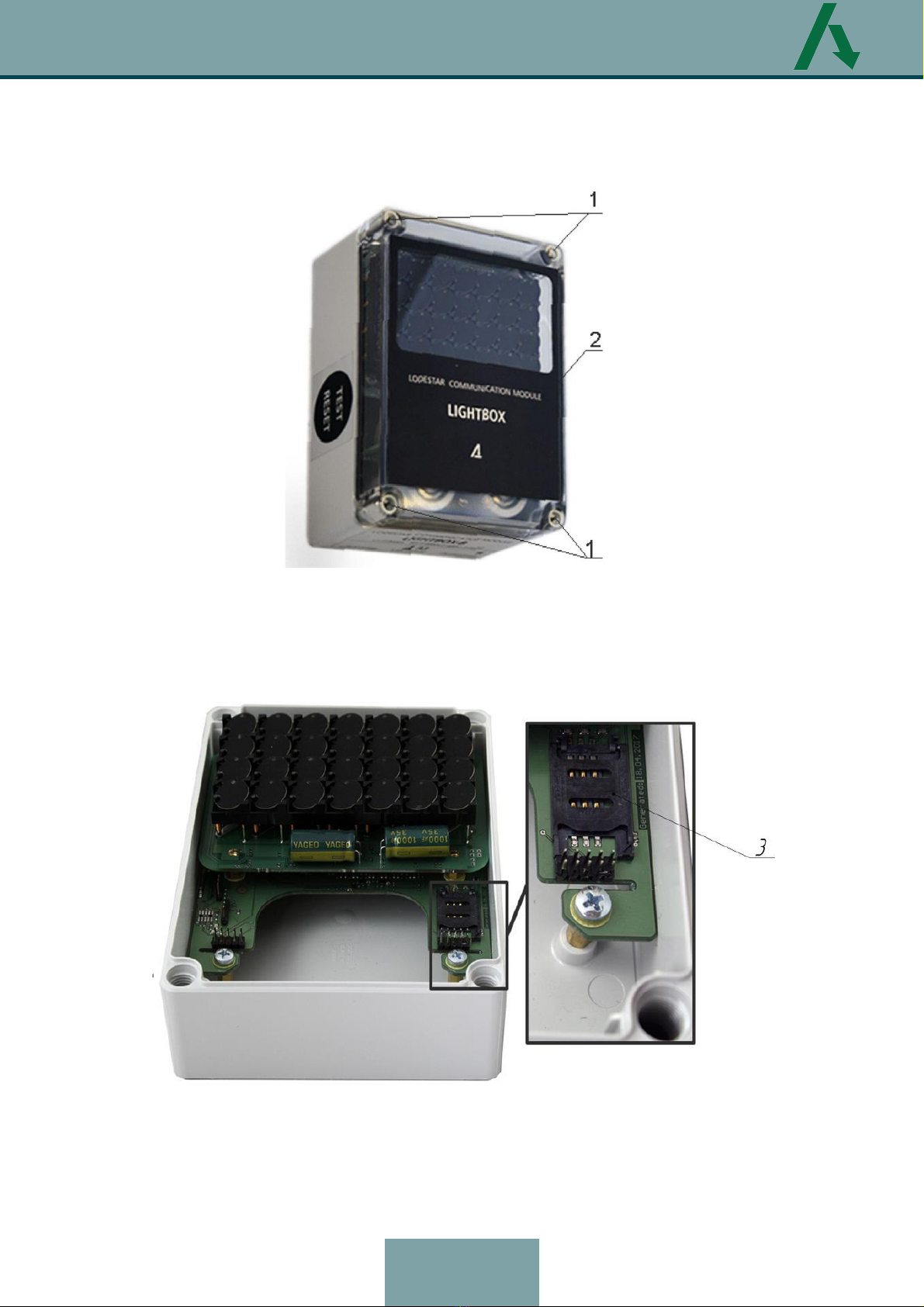
LightBox is a pole mountable communicaon module. LightBox is
designed to transmit data from fault indicators to the distribuon network
monitoring system KOMORSAN or a SCADA system.
The KOMORSAN system has its own web-interface for easy
management from the dispatcher's workplace and provides the possibility
of noficaon via text message and e-mail. The KOMORSAN system can be
integrated into any SCADA system via the IEC 60870-5-104 protocol.
By using proprietary data transfer protocol and informa on
exchange system opmized for extremely low power consumpon,
LightBox is powered by built-in baery pack and does not require any
external power. LightBox is equipped with addional means of indicaon
of fault occurrence - contrasng reflecve blinkers (flag).
Fault indicators, which are mounted on three phases of overhead
lines, transmit data to LightBox. LightBox provides the real-me
analysis of the informaon derived from all fault indicators.
In case of fault detecon LightBox immediately starts communicaon
session with a server for a fault data transmission and turns blinkers’
yellow side.
The standard configuraon of data transmission is made by
means of a built-in GSM modem through the cellular network.
LightBox is equipped with a built-in Bluetooth standard radio
channel (2.4 GHz). LightBox can communicate with Lodestar fault
indicators and a remote control via a bidireconal wireless connecon.
LightBox configuraon is made via the KOMORSAN WEB-client
soware and a remote control.
5Revision D2 (March 2020)
UM LightBox

SIM CARD INSTALLATION AND BATTERY PACK
CONNECTION
NOTE:
LightBox is delivered with a baery disconnected. Before installaon, insert
a SIM card and connect a baery pack.
NOTE:
●
SIM card must not request a PIN code;
●
It is recommended to use SIM cards of industrial design, intended for use
in telemacs devices (such cards have extended modes of operaon,
including temperature range and increased authorizaon counter);
The GPRS connecon sengs of the mobile network operator must be
configured in the device in advance. The primary GPRS access sengs are
recorded in the device by the manufacturer in accordance with the
quesonnaire.
If the access sengs for the SIM card you are installing are different
from those specified in the quesonnaire, the device needs to be
reconfigured using the KOMORSAN Web-client soware.
In order to change the sengs of LightBox, a SIM card that can
access GPRS with the sengs recorded should be installed in the
device.
NOTE:
A SIM-chip can be installed into LightBox. A SIM-chip can be installed by
the manufacturer only, its self-replacement is not possible.
IMPORTANT:
Either installing or replacing a SIM card, it is recommended to reset
LightBox and check its performance.
6Revision D2 (March 2020)
UM LightBox

FLAG
For SIM card installaon and Baery pack connecon follow step-by-step
instrucons:
Fig.1.1
1. Unscrew the screws-1 and remove cover-2 (Fig.1.1.)
2. At the picture the SIM card holder (3) (Fig.1.2.)
Fig.1.2
7Revision D2 (March 2020)
UM LightBox

For baery pack connecon follow step-by-step instrucons:
1) Unscrew the screws-1 and remove cover-2 (Fig.1.1.)
2) Prepare the baery pack (Fig.1.7.)
Fig.1.7
3) Put the baery pack into grooves C, connector А – А, connector B - B
(Fig.1.8).
Fig.1.8
9Revision D2 (March 2020)
UM LightBox

3. Open the SIM card holder as
shown in the Fig.1.3
4. Install the SIM card as
shown in the Fig.1.4
Fig.1.6
5. Close the SIM card holder
as shown in the Fig.1.5
6. Install cover-2 and ghten
the screws - 1
Fig.1.5
Fig.1.4
Fig.1.3
8Revision D2 (March 2020)
UM LightBox

4) Install baery pack against the stop (Fig.1.9).
Fig.1.9
5) Install cover-2 and ghten the screws – 1 (Fig.1.6)
NOTE:
Aer SIM card replacement, it is recommended to reset LightBox.
Normal baery pack life up 15 years. Baery pack life depends on the
number of connected sets, interference situaon, quality of GSM-
coverage, the number of recorded faults, number of sessions with the
server.
NOTE:
Before replacing a baery pack, contact the manufacturer for ordering a
new baery pack.
10 Revision D2 (March 2020)
UM LightBox

INDICATION TEST
Indicaon test should be performed before installaon , in order
to check the funconality of LightBox.
To start click on the icon "LodestarAPP" on the smartphone.
Fig.2.1
Aer turning on the mobile device and start LodestarAPP the ether is
scanned and a list of available Devices is given. The user is provided with
a list of found devices, in which select the desired Device and press the
"Connect" buon.
Fig.2.2
Revision D2 (March 2020)
UM LightBox 11

The user can list filter by serial number by calling the buon
Fig.2.3
To connect a smartphone to the device select the desired device in the
list of the available devices (see figure 2.2) As a result, a connecon
to the mobile device is established, a session of communicaon
between the smartphone and the Device is established, and a pairing
request icon appears in the upper le corner (see figure 2.4). If the
pairing is not established within 30 seconds, the connecon is
terminated.
9
Fig.2.4
Revision D2 (March 2020)
UM LightBox 12

To
install
the pairing aer the appearance
of
the pairing
request icon complete the following steps:
1) Swipe down from the top of the screen, then in the p o p - u p
window click "Pairing request" link (see figure 2.5);
Fig.2.5
2) In the proposed window click "Pair" (see figure 2.6)
Fig.2.6
Revision D2 (March 2020)
UM LightBox 13

3) Repeat step 1.
4) In the proposed window click "Pair"
Fig.2.7
5) As a result, a connecon to the device is made, a
communicaon session of the smartphone with the Device is
established. To check indicaon press “Enable indicaon”.
Fig.2.8
Revision D2 (March 2020)
UM LightBox 14

5) Aer pressing “Enable indicaon” in 120 sec. flag turns
yellow.
Fig.2.9
6) To disable indicaon press “Disable indicaon”
Fig.2.10
Revision D2 (March 2020)
UM LightBox 15

7) Aer pressing “Disable indicaon” in 120 sec. flag turns
black.
Fig.2.11
8) The main menu can be accessed by pressing the buon
in the upper le corner (see figure 2.12, 2.13)
Fig.2.12 Fig.2.13
Revision D2 (March 2020)
UM LightBox 16

C
A B
INSTALLATION
Check serial numbers of LightBox and a set of Lodestars in
product's passports before installaon.
SET of 3 PRODUCTS: A, B, C
NOTE:
Do not forget to write down the
date of the installaon upon its
complete on in a product’s
passport.
Aer baery pack is connected and a SIM card is installed, LightBox
connects to the KOMORSAN system.
Run KOMORSAN WEB-client soware and check the connecon.
To check the connecon in the KOMORSAN WEB-client soware,
see manual for the KOMORSAN WEB-client soware.
NOTE:
Aer LightBox installaon on a pole it is recommended to TEST/RESET
LightBox with a magnet. For LightBox test/reset, see secon RESET.
Revision D2 (March 2020)
UM LightBox
Communication module
The Communication module Lightbox is ready for service and meets
CL4 serial number 1900009
CL4 serial number 1900010
CL4 serial number 1900011
FI-address:
Lightbox serial number 1900012
INSTALLATION with Lodestar CL4 SET:
designed by
Lightbox
The package includes :
technical conditions:
Designed by A3 R&M company
Quality Control pass: ______Feb. 2019_________
Control Department
representative's signature_________
/_______________________
/
Stamp
Date of installation __________________________________________________
A-TREE R&D&M Co
CONTACT DETAILS
Support: [email protected]
+7 499 450 55 07
www.a3.energy
PRODUCT PASSPORT
Electromagnetic Compatibility
IEC 61000-6-2 | Electro Magnetic Compatibility
Environmental
IEC 60529 | IP 65 Protection Level
17

LightBox can be installed on any types of poles.
To install LightBox on a pole follow step-by-step instrucons in Figure 3
below .
1. Insert one end of the strap through the band loop and bend it in the opposite
direcon from the “ears”.
2. Pass the strap through the mounng hole in LightBox housing. Fasten
LightBox housing to a pole using the strap, fixing both ends of the strap in the
band loop.
3. Insert the strap into the instrument and ghten it up by turning the
ghtened lever. Aer the necessary tension is reached, bend the strap in the
band loop in the opposite direcon from the tension side, cut off the excess
8
7
6
5
3
2
1
Revision D2 (March 2020)
UM LightBox
piece of the strap.
18

CONFIGURATION
Configuraon of LightBox can be done via the KOMORSAN WEB-client
soware.
Paral configuraon* of LightBox can be done via a remote control.
LightBox Remote control
* For LightBox sengs, which can be adjusted via a remote control, see
table “SETTINGS” on page 20.
Lodestar sengs are stored in LightBox. For Lodestar configuraon can be
found in Lodestar manual.
Revision D2 (March 2020)
UM LightBox
LightBox soware
The KOMORSAN WEB-client
19

SETTINGS
Table of Sengs
NAME VALUE REMOTE
CONTROL
THE KOMORSAN WEB-
CLIENT SOFTWARE
Reset me
of blinker
from 1h to 99h v
from 1min to 43200min (30 days) v
Communicaon
period
from 10min to 43200min (30 days) v
Soware update vv
Event types to
registrate v
Log of events reading v v
Communicaon parameters
Server name v v
Server key vv
Server port vv
Access to GPRS service parameters
Login v v
Password v v
APN v v
NOTE:
The default value of the communicaon period seng is twice a day. It is
recommended to set the value of the communicaon period no more
than 4 mes a day.
Aer the sengs of the connected changing, reset the device. It is
required to make new connecons valid.
Revision D2 (March 2020)
UM LightBox 20
Table of contents
Popular Lighting Equipment manuals by other brands

Displays2go
Displays2go SPLBP71CP user manual

Soundoff Signal
Soundoff Signal mPower EMPR10004-WW manual

Hella
Hella KL 7000 Mounting instructions

Intermatic
Intermatic EL100 Installation and user instructions

Daintree
Daintree GE Current Tetra GEPS24-25U-NA installation guide

Somogyi Elektronic
Somogyi Elektronic home FLP 1100 SOLAR instruction manual

Atlas Copco
Atlas Copco HiLight H5+ Hd ESF instruction manual

Clevertronics
Clevertronics FBKLED Series Installation & maintenance instructions

RAB
RAB SMSLES2X13 installation manual

Lumencor
Lumencor LIDA Light Engine instruction manual

ADB Safegate
ADB Safegate RELIANCE Omni 1-Dome user manual

ShowPro
ShowPro MoonLite 80 HEX user manual