Loea Corporation L2700 User manual

L2700 User’s Manual
DU002700-01 8/15/2007
Loea Corporation
733 Bishop Street, Suite 1717
Honolulu, HI 96813
Phone: (808) 521-4908
Fax: (808) 521-4906
www.loeacom.com
USER MANUAL
L2700 Millimeter-wave
Point-to-Point Radio
Version 1.0
August 15, 2007

L2700 User’s Manual
DU002700-01 8/15/2007
Loea Corporation
733 Bishop Street, Suite 1717
Honolulu, HI 96813
Phone: (808) 521-4908
Fax: (808) 521-4906 www.loeacom.com
2
Table of Contents
GENERAL SAFETY NOTICES................................................................................................. 4
1. OVERVIEW.......................................................................................................................... 6
1.1 DESCRIPTION.................................................................................................................. 6
1.2 L2700 COMMON APPLICATIONS AND FEATURES.......................................................... 6
2. INSTALLATION PROCEDURES ..................................................................................... 9
2.1 INTRODUCTION............................................................................................................... 9
2.2 STANDARD LINK COMPONENTS..................................................................................... 9
2.3 GENERAL INSTALLATION REQUIREMENTS ................................................................. 10
2.4 CONSTRUCTION OF STEERING SYSTEM (PART NUMBER MT-24) .............................. 11
2.4.1 Assemble Azimuth and Elevation Control Arms (see Figure 3) .......................... 11
2.4.2 Assemble Antenna Mount Plate and Azimuth Arms (see Figure 4)..................... 12
2.4.3 Assemble Antenna Mount Plate and Pole Plate (see Figure 5) ............................ 12
2.5 ATTACH ASSEMBLY TO MAST AND ATTACH ANTENNA (SEE FIGURE 6).................... 14
2.6 ATTACH TRANSCEIVER TO STEERING SYSTEM (SEE FIGURE 7)................................. 15
2.7 CABLING TO THE RADIO (SEE FIGURE 8)..................................................................... 16
2.8 INTERFACING TO RSSI PORT (SEE FIGURE 13)........................................................... 23
2.9 ALIGNMENT TECHNIQUES (SEE FIGURE 15)................................................................ 25
2.10 VERIFICATION OF BIT ERROR RATE (BER)................................................................ 26
2.11 FINAL SYSTEM COMMISSIONING................................................................................. 27
3. SYSTEMS INTEGRATION.............................................................................................. 28
3.1 STANDARD SYSTEM DEMARCATION BOX REQUIREMENTS......................................... 28
3.2 BASIC INFORMATION ON LOEA INTERFACE................................................................ 28
3.3 LINK MONITORING ...................................................................................................... 29
3.3.1 Network Management System Operation............................................................. 29
3.3.2 NMS Data Transfer............................................................................................... 29
3.4 RS-232 SERIAL LINK INTERFACE................................................................................ 30
3.5 GROUNDING PROCEDURES........................................................................................... 34
3.5.1 Single Point Grounding......................................................................................... 34
3.5.2 Rack Cabinet Grounding....................................................................................... 36
3.5.3 An Effective Earth Ground................................................................................... 37
3.5.4 At the Tower......................................................................................................... 38
3.5.5 Conclusion ............................................................................................................ 39
APPENDIX A - FIELD SERVICE FORM .............................................................................. 41
APPENDIX B – LIST OF SNMP MIB GROUPS ................................................................... 43
APPENDIX C –EXAMPLE OF INSTALLING THE L2700 MIB........................................ 46

L2700 User’s Manual
DU002700-01 8/15/2007
Loea Corporation
733 Bishop Street, Suite 1717
Honolulu, HI 96813
Phone: (808) 521-4908
Fax: (808) 521-4906 www.loeacom.com
3
List of Figures and Tables
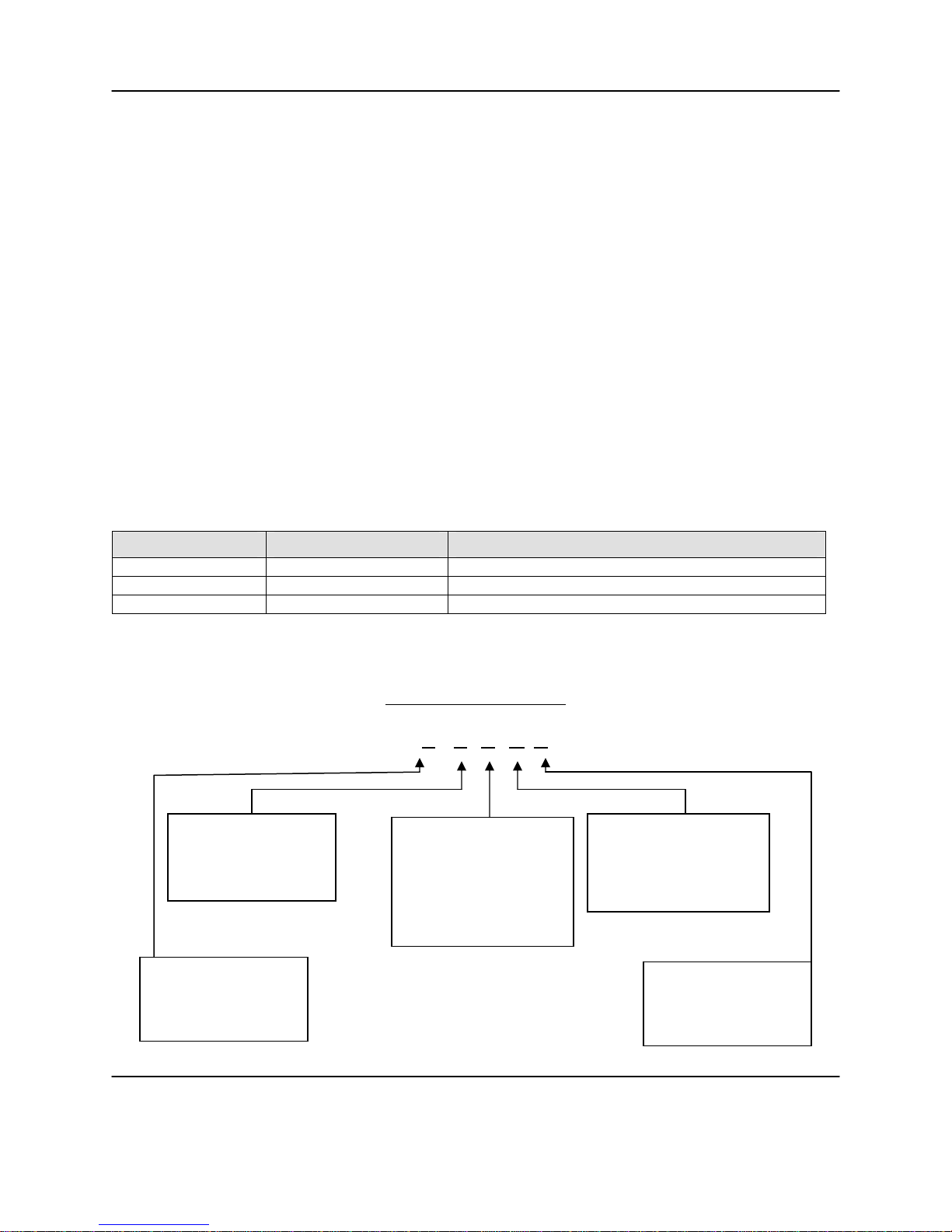
FIGURE 1. TYPICAL L2700 APPLICATIONS....................................................................................... 7
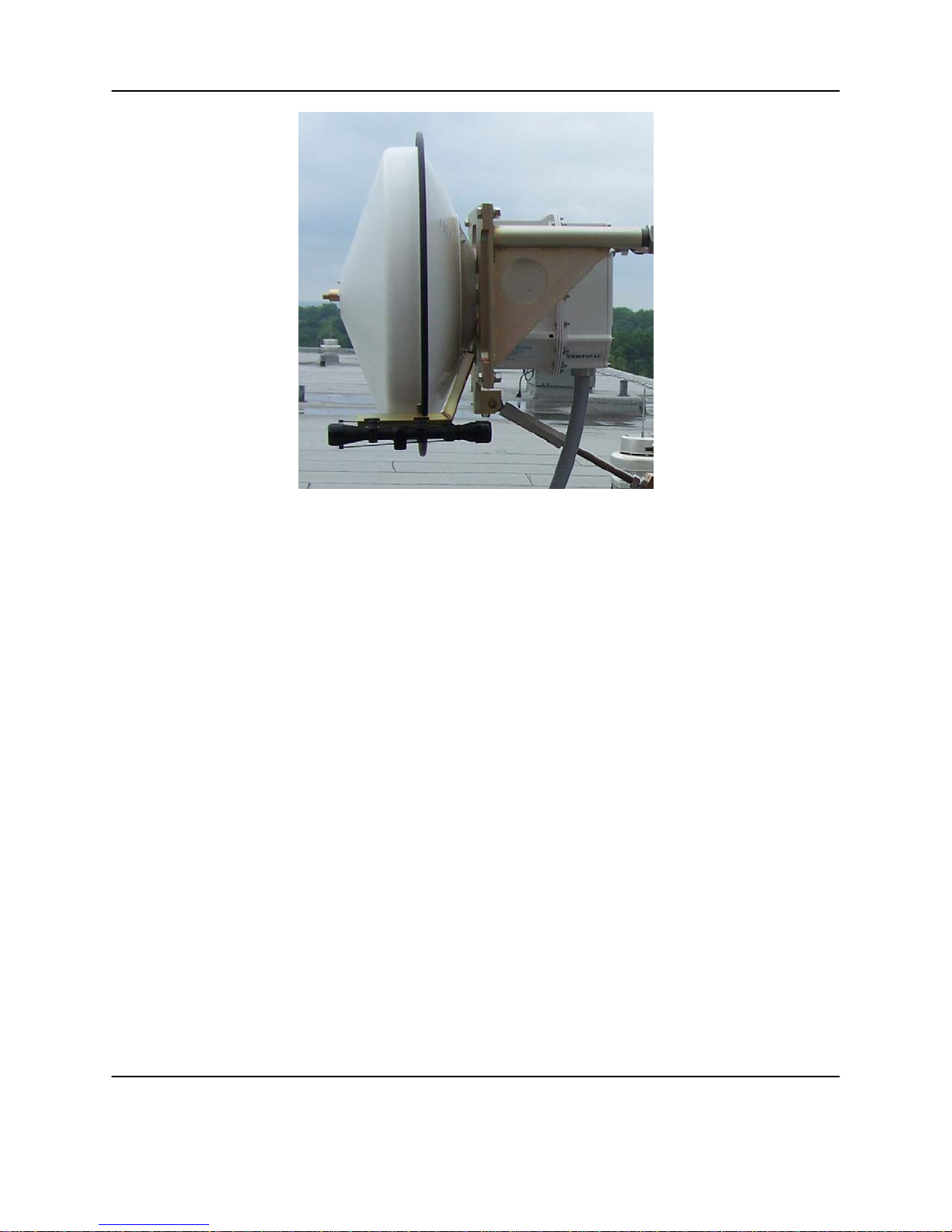
FIGURE 2. L2700 WITH 2FOOT ANTENNA........................................................................................ 8
FIGURE 3. AZIMUTH AND ELEVATION CONTROL ARMS. ................................................................ 11
FIGURE 4. ASSEMBLY OF ANTENNA MOUNT PLATE AND AZIMUTH CONTROL ARMS. ................... 12
FIGURE 5. ANTENNA MOUNT PLATE AND POLE PLATE ASSEMBLY................................................ 13
FIGURE 6. ATTACHING ASSEMBLY TO MAST AND ATTACH ANTENNA........................................... 14
FIGURE 7. ATTACHING TRANSCEIVER TO STEERING SYSTEM......................................................... 15
FIGURE 8. INSIDE RADIO SERVICE COMPARTMENT........................................................................ 16
FIGURE 9FEMALE AC POWER RECEPTACLE.................................................................................. 17
FIGURE 10. EXAMPLE OF DC POWER CONNECTION USING RG6 CABLE......................................... 18
FIGURE 11. INSIDE THE RADIO SERVICE COMPARTMENT............................................................... 19
FIGURE 12: TYPICAL LC DUPLEX MALE CONNECTOR................................................................... 20
FIGURE 13: TYPICAL PLUGGABLE GBIC........................................................................................ 20
TABLE 2A:SINGLE-MODE FIBER OPTIC INTERFACE SPECIFICATION............................................... 21
TABLE 2B:MULTI-MODE FIBER OPTIC INTERFACE SPECIFICATION................................................ 22
FIGURE 14. RADIO REAR COVER REMOVED SHOWING SERVICE COMPARTMENT. ......................... 23
FIGURE 15. TYPICAL RSSI CHART ................................................................................................ 24
FIGURE 16. ALIGNMENT TECHNIQUE............................................................................................. 25
FIGURE 17. ANTENNA PATTERN WITH SIDE LOBES........................................................................ 26
FIGURE 17. MAIN MENU AS SHOWN IN (WINDOWS)HYPERTERMINAL. ........................................ 31
FIGURE 18 MAIN MENU OPTION ISHOWS IP ADDRESS FOR RADIO. ............................................... 32
FIGURE 19. MAIN MENU OPTION SWITH SETUP MENU OPTIONS................................................... 33
FIGURE 20. SINGLE POINT GROUNDING ......................................................................................... 35
FIGURE 21. TWO METHODS OF SINGLE POINT GROUNDING .......................................................... 35
FIGURE 22. EARTH GROUND ......................................................................................................... 37
FIGURE 23. TOWER GROUND......................................................................................................... 38
FIGURE C1. EXAMPLE OF SNMPC MANAGEMENT CONSOLE SCREEN............................................ 47
FIGURE C2 SNMPC MIB BROWSER SELECTION........................................................................... 48
FIGURE C3 SNMPC MIB BROWSER. ............................................................................................. 49
FIGURE C4. SNMPC ‘SYSTEM’FOLDER SELECTION...................................................................... 50
FIGURE C5. SNMPC ‘SYSCONTACT’, ‘SYSNAME’AND ‘SYSLOCATION’DATA ENTRY.................. 51
FIGURE C6. SNMPC SELECTION OF LOEA FOLDER AT BOTTOM OF ‘PRIVATE’FOLDER LIST........ 52
FIGURE C7 THE ‘LOEA’FOLDER SHOWING 5DIFFERENT LOEA MIB GROUPS................................ 53
FIGURE C8. INDIVIDUAL SNMP VARIABLES FOR GROUP............................................................... 54
FIGURE C9. THE SYSTEM GROUP ICSYSGROUP............................................................................ 55
FIGURE C10. THE INTERNAL GROUP LCINTGROUP:....................................................................... 56
FIGURE C11. THE FIBER GROUP LCFIBGROUP:............................................................................. 57
FIGURE C12. THE RF GROUP LCRFGROUP:.................................................................................. 58
FIGURE C13. THE TRAP CONTROL GROUP LCTCGROUP:.............................................................. 59

L2700 User’s Manual
DU002700-01 8/15/2007
Loea Corporation
733 Bishop Street, Suite 1717
Honolulu, HI 96813
Phone: (808) 521-4908
Fax: (808) 521-4906 www.loeacom.com
4
GENERAL SAFETY NOTICES
FCC NOTICE
This equipment complies with the FCC radiation exposure limits set forth for an uncontrolled
environment when installed as directed. This equipment should be installed and operated with
fixed mounted antennas that are installed such that these antennas will have a minimum of 2m of
separation distance between the antenna and all persons during normal operation.
This device complies with Part 101 of the FCC Rules.
This device is labeled with the following FCC ID number:
S2N-L2700-2
PROFESSIONAL INSTALLATION REQUIRED
The L2700 must be installed as a system by experienced antenna installation professionals who
are familiar with Radio Frequency (RF) issues such as gains and losses, as well as local building
and safety codes. Failure to do so will void the product warranty and may expose the end user to
excessive RF hazard.
Regulations regarding maximum antenna gains, power output and maximum permissible
exposure vary from country to country. It is the responsibility of the end user to operate within
the limits of these regulations and to ensure that the professional installers who install this device
are aware of these regulations. All antennas are intended to be installed outdoors.
MICROWAVE RADIO RADIATION WARNING
When installed properly, this product complies with the limits for human exposure to radio
frequency (RF) fields adopted by the Federal Communications Commission (FCC). The product
is designed so that under normal working conditions, microwave radiation directly from the
transceiver is negligible when compared with the permissible limit of continuous daily exposure
recommended in the United States by ANSI/IEEE C95.1-1991 (R1997), Safety Levels with
Respect to Human Exposure to Radio Frequency Electromagnetic Fields, 3kHz to 300GHz.

L2700 User’s Manual
DU002700-01 8/15/2007
Loea Corporation
733 Bishop Street, Suite 1717
Honolulu, HI 96813
Phone: (808) 521-4908
Fax: (808) 521-4906 www.loeacom.com
5
Microwave signal levels that give rise to hazardous radiation levels can exist within transmitter
power amplifiers, associated RF multiplexers, and antenna systems. Do not disconnect RF
coaxial connectors, open microwave units, or break down any microwave screening while the
radio equipment is operating.
LASER SAFETY NOTICE
This product complies with CFR 1040.10 and 1040.11. The product includes a Class I laser
utilized as a fiber optic driver. Class I lasers do not emit radiation at known hazardous levels.
However, it is recommended that maintenance or service personnel should never look at an open
fiber end or connector that is carrying a live signal. During use, this optical fiber
communications system is completely enclosed except if an accidental break occurs in the
system cable, or if the patch cable becomes accidentally disconnected from the demarcation box.
There are no controls or adjustments other than power ON/OFF that may be accessed by the
user.
CAUTION: Use of controls or adjustments or performance of procedure other than those
specified in this Manual may result in hazardous radiation exposure.
CONSTRUCTION SAFETY NOTICE
Note that every area of the country has its own codes of safety and construction. Installations
like this must comply with these codes. It is the installer/user’s responsibility to understand what
codes apply and to ensure that the installation conforms to these codes.

L2700 User’s Manual
DU002700-01 8/15/2007
Loea Corporation
733 Bishop Street, Suite 1717
Honolulu, HI 96813
Phone: (808) 521-4908
Fax: (808) 521-4906 www.loeacom.com
6
1. Overview
1.1 Description
The L2700 is a point-to-point, fixed wireless, ultra-broadband access product which operates in
the licensed upper millimeter wave spectrum from 71.0-86.0GHz. The L2700 can carry high
capacity payloads (up to 1.25Gbps- full duplex) with high availability in all weather. In most
locations in the United States, the L2700 will have 99.999% weather availability at roughly 1.6
kilometer. It deploys quickly and inexpensively with proper planning and preparation as
outlined in this manual. Loea RF products are intended for installation by professional Loea
certified installers only.
1.2 L2700 Common Applications and Features
The L2700 is a last mile access solution and a replacement for buried/aerial fiber cable such as
wireless backhaul, last mile access and LAN/WAN extensions.
The L2700 is rapidly deployable and re-commissionable making it an ideal solution for
temporary bandwidth or for emergency situations that could cause an interruption to buried
technologies.
In short, most applications of fiber cable in the last mile are potential applications for the L2700.

L2700 User’s Manual
DU002700-01 8/15/2007
Loea Corporation
733 Bishop Street, Suite 1717
Honolulu, HI 96813
Phone: (808) 521-4908
Fax: (808) 521-4906 www.loeacom.com
7
Figure 1. Typical L2700 Applications.
Product Features:
•Operation in the Part 101 licensed 71.0-76.0GHz & 81.0-86.0GHz band.
•FCC and NTIA certified
•Standard LC fiber optic interface
•110V AC power, 50W peak consumption
•-48 Volt telecom standard DC power (option)
•19 dBm peak output power – OOK Modulation
•All weather performance
•OSI Layer 1 data transmission
oInteroperable with most fiber optic COTS switch, router and encryption devices.
oPlug and play with existing networks.
•Secure Transmission and narrow beam widths
oLow Probability Intercept and Low Probability Detection (LPILPD)
oCo-existence of many users with low likelihood of interference
•Operating Temperature from -20C to +50C

L2700 User’s Manual
DU002700-01 8/15/2007
Loea Corporation
733 Bishop Street, Suite 1717
Honolulu, HI 96813
Phone: (808) 521-4908
Fax: (808) 521-4906 www.loeacom.com
8
Figure 2. L2700 with 2 Foot Antenna

L2700 User’s Manual
DU002700-01 8/15/2007
Loea Corporation
733 Bishop Street, Suite 1717
Honolulu, HI 96813
Phone: (808) 521-4908
Fax: (808) 521-4906 www.loeacom.com
9
2. Installation Procedures
2.1 Introduction
This manual provides basic instructions on the assembly, alignment and verification of the Loea
L2700 system. In doing so, it outlines recommended tools and processes to use. A detailed
understanding of this manual and participation in a Loea training class is highly recommended
prior to starting any work on site. Only Loea Trained and Certified installers should perform
installation services on the L2700.
Please note that every area of the country has its own codes of safety and construction.
Installations must comply with these codes. It is the installer/user’s responsibility to understand
what codes apply and to ensure that the installation conforms to these codes.
2.2 Standard Link Components
Description Part # Comments
Transceiver Pair L2700-XYZV Radio Pair Only
2’ antenna A24-FCM Two (2) Antenna’s required for a link
Steering Mechanism MT-24 Two (2) Steering Mechanisms required for a link
Table 1 – Basic L2700 Components
Part Number Format
L270N – X Y Z V
X – Orientation
V = Vertical
H = Horizontal
Z – Optical Interface
S = 1310nm
M = 850nm
Y – Payload Standard
A = GIGE (1.25Gbps - full
duplex)
B = OC12 (622Mbps – full
duplex)
C = 1.42Gbps – full duplex
V – Input Power
A = 110V (nom) AC
B = -48 V (nom) DC
N – Terminal Config
0 = Complete link
7 = Tx at 73.5GHz
8 = Tx at 83.5GHz

L2700 User’s Manual
DU002700-01 8/15/2007
Loea Corporation
733 Bishop Street, Suite 1717
Honolulu, HI 96813
Phone: (808) 521-4908
Fax: (808) 521-4906 www.loeacom.com
10
2.3 General Installation Requirements
Before the installation of a Loea link, certain steps must be taken to ensure that the installation
will be successful.
A. Site Survey: During a site survey a certified Loea surveyor can assess the
environment of the installation, ensure that the physical conditions of the site are
appropriate, indicate where building connections need to be available and ensure that
Line of Sight (LOS) exists between the two end points.
B. FCC Part 101 License: Loea’s band of operation is licensed by the FCC for non-
federal government users and by the NTIA for federal government and DOD users.
Prior to deployment, a license is required. For more information on obtaining a
license for operation of this radio in the 70 and 80 GHz bands see
http://wireless.fcc.gov/services/millimeterwave/ and select the “nationwide license”
link. There is an application form and information pertaining to current license fees
at this site. If you are a federal government user, your spectrum officer should be
able to get a license with our J/F12 number 8138. Please contact Loea directly with
any questions.
C. Installation of Mast and Demarcation: A standard 4in mast (4.5in O.D.) must be
installed at a position and specific height as specified in the Site Survey. To facilitate
connection to the building’s network; fiber for communications, 110V AC (Required
UPS -Cyber Power UPS Model #CPS625AVR or equivalent for AC mode) or
optional -48VDC, and optional Ethernet for monitoring are required in a demarcation
box per the specifications in this manual and specifically as defined in the Site
Survey.
D. Bench Test: Loea recommends that the transceivers be tested after delivery to the site
and prior to installation on the mast to ensure that no damage occurred during
shipping and to familiarize customer with radio operation. To perform a bench test:
a) Separate the transceivers by approximately 5 feet on a wooden or non-metallic
surface without the antennas attached. Align the radios so that the feed horns are
in the same RF orientation (to do this situate the radio housing so that the conduit
hole on each radio is pointing upward) and pointed directly at each other with
absorber material between the feed horn. When user can verify an RSSI
(Receive Signal Strength Indicator) value a link has been established. Then when
BER performance is verified the link is functional. See reference Sections 2.7,
2.8 and 2.9.
b) If possible, a complete end-to-end test is recommended with switching and/or
encryption devices. The L2700 is generally a plug and play device, it is
recommended to do this to avoid de-bugging in the field.
E. System Commissioning: Upon install completion, metrics from the install site must
be recorded and verified to ensure that the transceivers are performing as expected.
The “Loea Field Service Data” form (see Appendix A) should be forwarded to Loea
following the installation. This will assist Loea’s technical service and help desk
personnel assess problems should a link fail to operate. It is also recommended that
the end user/owner keep a copy for their records.

L2700 User’s Manual
DU002700-01 8/15/2007
Loea Corporation
733 Bishop Street, Suite 1717
Honolulu, HI 96813
Phone: (808) 521-4908
Fax: (808) 521-4906 www.loeacom.com
11
2.4 Construction of Steering System (Part Number MT-24)
2.4.1 Assemble Azimuth and Elevation Control Arms (see Figure 3)
Note: Some parts may come pre-assembled. Each assembly step is included for reference.
A Loea training class is highly recommended prior to a user installation.
Requires: two MRP-2003 Azimuth arms (5), one MRP-2005/1 Gross adjustment nut (2), one
MRP-2005/2 Fine adjustment nut (4), one MRP-2007 Elevation adjustment nut (6), two RH
threaded ball joint ends (3), one LH threaded ball joint end (1), ¾”-10 Threaded rod (7), and one
¾” jam nut (8).
Thread the left hand threaded ball joint (1) halfway into the gross adjustment nut (2). Thread one
right hand threaded ball joint (3) equally into the fine adjustment nut (4). Thread each
adjustment nut about halfway into an Azimuth arm (5).
Figure 3. Azimuth and Elevation Control Arms.
Thread the jam nut (8) and the course end (6a) of the Elevation adjustment nut (6) onto the one
end of the ¾”-10 threaded rod (7) far enough to reach the hollow portion of the Elevation nut.
Thread the ball joint (3) equally into the fine end of the adjustment nut (6b).

L2700 User’s Manual
DU002700-01 8/15/2007
Loea Corporation
733 Bishop Street, Suite 1717
Honolulu, HI 96813
Phone: (808) 521-4908
Fax: (808) 521-4906 www.loeacom.com
12
2.4.2 Assemble Antenna Mount Plate and Azimuth Arms (see Figure 4)
Requires: one MRP-2006 Mount plate (9), one MRP-2008 pillow block (10), four ½” Hardware
Assemblies (11) consisting of [½”- 13 x 1-3/4” bolt, hex nut, lock washer, flat washer], and three ¼”-
20 socket head cap screws (12).
Position the mount plate (9) so the offset tab is on the lower right. Locate the three ¼”-20
threaded holes on the tab and fasten the pillow block (10) to the mount plate with the socket head
cap screws (12). The application of Lock-Tite™ or an equivalent compound during this step is
recommended.
Figure 4. Assembly of Antenna Mount Plate and Azimuth Control Arms.
Position each Azimuth arm with adjustment controls up, on the backside of the mount plate
capturing the ½” through holes of the upper and lower tabs on each side of the mount plate.
Fasten the arms to the mount plate using the ½” hardware assemblies (11).
2.4.3 Assemble Antenna Mount Plate and Pole Plate (see Figure 5)

L2700 User’s Manual
DU002700-01 8/15/2007
Loea Corporation
733 Bishop Street, Suite 1717
Honolulu, HI 96813
Phone: (808) 521-4908
Fax: (808) 521-4906 www.loeacom.com
13
Requires: one MRP-2002 Pole plate (13), one MRP-2010 Elevation Lock nut (14), one ball joint
bearing (15), three ¾”-10 socket head cap screws (16), and one ¾” jam nut (8).
Position the pole plate (13) so that the bearing block for the Elevation control arm is on the lower
left. Securely brace the pole plate and gently tap the ball joint bearing (15) into the block with a
bearing drift or large socket. Orient the two plates so that the ball joint ends of the Azimuth
control arms line up with the ¾” tapped holes on each end of the pole plate cross beam. Next,
fasten the ball joint ends to the cross beam of the pole plate by inserting the ¾” socket head
screws (16) through the ball joint and thread into the tapped ends. Tighten until snug, do not
over tighten or torque the ball joint screws.
Figure 5. Antenna Mount Plate and Pole Plate Assembly.
Thread the jam nut (8) halfway up the free end of the Elevation (threaded rod) arm. Slide the
free end through the ball joint bearing (15) of the pole plate. Rotate the antenna mount plate so
the ball joint end attached to the other end of the Elevation arm lines up with the ¾” tapped hole
in the adjacent side of the pillow block. Secure the Elevation arm to the pillow block in the same
manner as the Azimuth arms. Thread the Elevation lock nut (14) onto the free end of the
Elevation arm. Adjust the Elevation lock nut and the ¾” jam nut (8) as needed to minimize
movement of the antenna mount plate during final assembly.

L2700 User’s Manual
DU002700-01 8/15/2007
Loea Corporation
733 Bishop Street, Suite 1717
Honolulu, HI 96813
Phone: (808) 521-4908
Fax: (808) 521-4906 www.loeacom.com
14
2.5 Attach Assembly to Mast and Attach Antenna (see Figure 6)
Requires: two U-Bolt Assemblies (17) consisting of [ one standard 4’’mast (4.5” diameter actual),
½”-13 U-bolts, two hex nuts, two lock washers], four 3/8”-16 bolts and flat washers (18), and
Antenna (19).
Lifting the steering assembly from the front, press the pole plate against the mast using the
parallel runners on the backside to steady the assembly while the two U-bolts (17) are installed.
Once the steering system is shifted into the desired position the plate’s runners will bind to the
mast as the U-bolts are tightened so as to prevent the mount from inadvertently slipping.
Figure 6. Attaching Assembly to Mast and Attach Antenna.
Once the steering assembly is secured to the mast, locate the four 3/8” through holes correlating
with the four threaded holes located on the backside of the antenna. Position the antenna (19)
onto the mount plate. Secure the antenna to the mount using the 3/8” bolts and flat washers (18).
Although the steering system can accommodate course adjustments, steering assembly may need
to shift beyond the range of the Azimuth arms. The U-bolts can always be loosened enough to
permit a slightly greater rotation to correct such alignment issues.

L2700 User’s Manual
DU002700-01 8/15/2007
Loea Corporation
733 Bishop Street, Suite 1717
Honolulu, HI 96813
Phone: (808) 521-4908
Fax: (808) 521-4906 www.loeacom.com
15
2.6 Attach Transceiver to Steering System (see Figure 7)
Once the steering assembly with antenna attached is secured to the mast per 2.5 above, lift the
transceiver and pass it through opening ‘A’ in the steering assembly aligning the four 3/8”
through holes on the transceiver (21) with the four threaded holes (22) located on the mount
plate.
NOTE: Ensure the transceiver housing is positioned such that the correct RF orientation of
the radio is being installed.
Secure the transceiver to the mount plate using the 1/4”-20 bolts, and lock washers (20).
Figure 7. Attaching Transceiver to Steering System.
A

L2700 User’s Manual
DU002700-01 8/15/2007
Loea Corporation
733 Bishop Street, Suite 1717
Honolulu, HI 96813
Phone: (808) 521-4908
Fax: (808) 521-4906 www.loeacom.com
16
2.7 Cabling to the Radio (see Figure 8)
Before proceeding to the alignment of the link, the installer must complete the fiber, AC power
and Ethernet connections to the radio. Typically this will be carried out by passing the associated
cables thru a 1” diameter industry standard liquid-tight conduit from a demarcation box to the
radio.
Note: Make the network and power connections to the radio by removing the rear cover from the
radio to reveal the service compartment as shown in Figure 8.
Figure 8. Inside Radio Service Compartment
Begin by first passing the AC power cord (without connector) thru the conduit before attaching a
female AC power connector to the radio side of the power cord. Once the power cord has been
pulled thru, attach the female AC power connector (Fig.9) to the AC power cord. Then connect
the power cord to the AC plug located in the service compartment (see Fig 8).
TX/RX Fiber cable
connection. LC duplex male
terminated
Single Conduit Access
To Service Comp 1in.
(Power/Fiber/Ethernet)
Ethernet port-
RJ-45 Cat5
110VAC corded power connector.
UPS Required
Power Indicator
LED
BNC for ACG
Access
L2700 Radio

L2700 User’s Manual
DU002700-01 8/15/2007
Loea Corporation
733 Bishop Street, Suite 1717
Honolulu, HI 96813
Phone: (808) 521-4908
Fax: (808) 521-4906 www.loeacom.com
17
Figure 9 Female AC Power Receptacle
Note:The Loea transceiver’s standard configuration requires an 110V (nom) AC connection
with transient conditioning via an Un-interruptible Power Supply (UPS). Cyber Power’s
CPS625AVR or equivalent must be used and is to be supplied by the customer.
An optional telecom -48 Volt DC power supply is also available. If using the -48 volt
Option for power, with the power off, connect the RG6U cable supplied by Loea to the radio and
connect the other end to the demark box as shown in Figure 10. Figure 11 depicts the view from
inside the service compartment.

L2700 User’s Manual
DU002700-01 8/15/2007
Loea Corporation
733 Bishop Street, Suite 1717
Honolulu, HI 96813
Phone: (808) 521-4908
Fax: (808) 521-4906 www.loeacom.com
18
Figure 10. Example of DC Power Connection using RG6 Cable.
DC Power through
F connector
RG6U Cable Demark Box
(NEMA 4 Rated or
Equivalent)

L2700 User’s Manual
DU002700-01 8/15/2007
Loea Corporation
733 Bishop Street, Suite 1717
Honolulu, HI 96813
Phone: (808) 521-4908
Fax: (808) 521-4906 www.loeacom.com
19
Figure 11. Inside the Radio Service Compartment
Fiber Signal interface:A duplex male LC terminated fiber optic connection is the standard
interface inside the L2700 radio. For applications using the Gigabit Ethernet standard, it is
recommended the customer use Single Mode 1310nm. Multimode 850nm fiber is available as an
option but is not recommended due to the limited temperature and distance performance of
Multimode fiber and related components. For the OC-12 standard, it is required that the customer
use Single-mode 1310nm fiber.
RTN 48V
Power switch
Terminal Block

L2700 User’s Manual
DU002700-01 8/15/2007
Loea Corporation
733 Bishop Street, Suite 1717
Honolulu, HI 96813
Phone: (808) 521-4908
Fax: (808) 521-4906 www.loeacom.com
20
A graphic showing the required LC fiber connector to be used is shown in Fig. 12.
Figure 12: Typical LC Duplex Male Connector
The fiber connector will mate with the GBIC located in the service panel as shown in Fig.8. A
typical pluggable GBIC is shown in Fig. 13. Do not attempt to remove the GBIC unless
instructed to do so by a Loea engineer.
Figure 13: Typical Pluggable GBIC
Table of contents