manuals.online logo
Brands
  1. Home
  2. •
  3. Brands
  4. •
  5. Loewe
  6. •
  7. LCD TV
  8. •
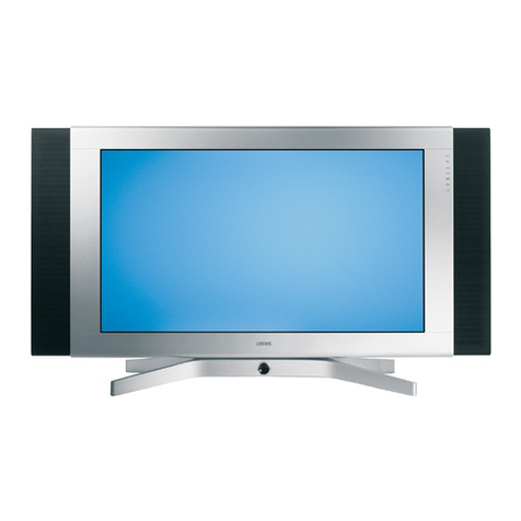
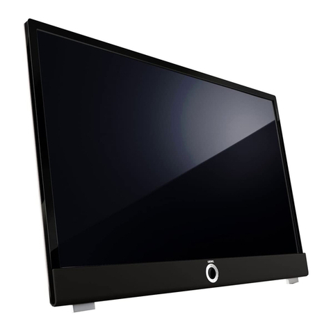
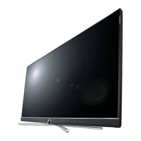
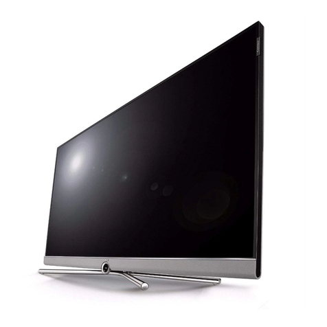
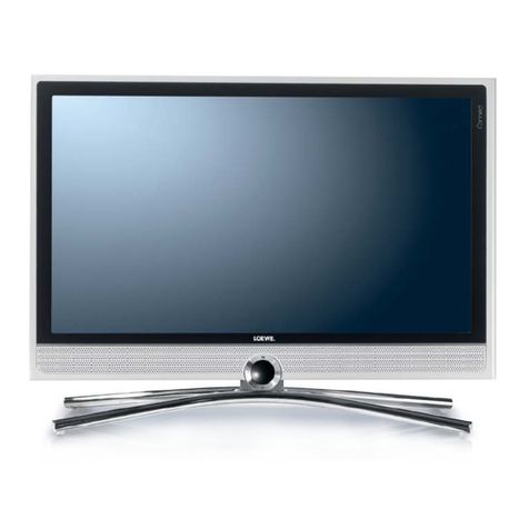
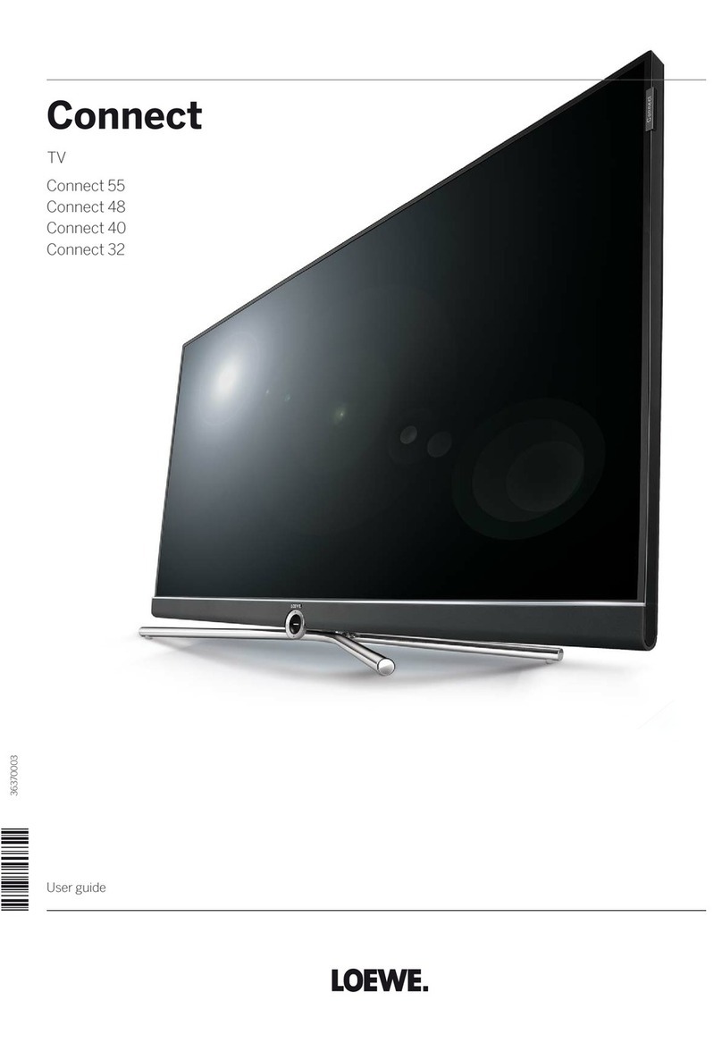
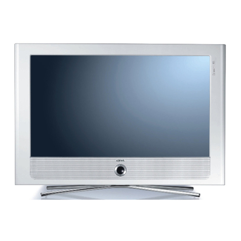
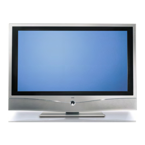
  9. Loewe Connect 22 SL User manual

Loewe Connect 22 SL User manual

SERVICEANLEITUNG
Service Manual. Manuel de Service. Manuale di Servizio.
Instrucciones de servicio. Service-instructies.
MB 180
230-98287.040
Connect 22 SL
Art.-Nr. 50405
Connect 26 SL
Art.-Nr. 50401
Xelos 32
Art.-Nr. 51429
2
Inhaltsverzeichnis
Sicherheitshinweise . . . . . . . . . . . . . . . . . 3
Service Loewe Connect /Xelos - TV . . . . . . . . . 4
Demontage Connect . . . . . . . . . . . . . . . . 5
Demontage Xelos . . . . . . . . . . . . . . . . . 7
Verkabelung Connect/Xelos . . . . . . . . . . . . .9
Schaltungsbeschreibung Connect/Xelos . . . . . . 15
Service Mode Befehle . . . . . . . . . . . . . . . 36
Service Menü Connect/Xelos . . . . . . . . . . . 38
TV Menü Connect/Xelos . . . . . . . . . . . . . 41
Baugruppenübersicht . . . . . . . . . . . . . . 60
Technische Daten Connect/Xelos . . . . . . . . . 61
Loewe Auslandsvertretungen . . . . . . . . . . . 88
Index
Security advice . . . . . . . . . . . . . . . . . . . 3
Service Loewe Connect / Xelos - TV . . . . . . . . 4
Removal Connect . . . . . . . . . . . . . . . . . . 5
Removal Xelos . . . . . . . . . . . . . . . . . . . 7
Wiring diagram Connect/Xelos . . . . . . . . . . . 9
Circuit description Connect/Xelos . . . . . . . . . 15
Service Mode instructions . . . . . . . . . . . . . 36
Service menu Connect/Xelos . . . . . . . . . . . 38
TV menu Connect/Xelos. . . . . . . . . . . . . . 41
Overview of components . . . . . . . . . . . . . 60
Technical data Connect/Xelos . . . . . . . . . . . 61
LOEWE foreign representations . . . . . . . . . 88
3
D
Hinweis zum Schutz gegen Elektrostatik
1. Elektrostatisch gesicherte MOS-Arbeitsplätze.
Der Umgang mit gegen Elektrostatik empndlichen Bauteilen
muß an einem elektrostatisch gesicherten MOS-Arbeitsplatz
erfolgen. Ein elektrostatisch gesicherter MOS-Arbeitsplatz
erdet über Entladungswiderstände sämtliche leitende Ma-
terialien einschließlich der Person. Nichtleiter werden durch
Luftionisation entladen. Die Integration von Lötkolben und
Meßgeräten in den gesicherten MOS-Arbeitsplatz ist nur
mit Trenntrafo in jedem der verwendeten Geräte möglich.
Die Meßgeräte-Massen werden ebenfalls mit Entladungs-
widerständen geerdet.
2. Gesicherte Verpackung durch leitfähige Materialien.
Zum Schutz gegen Elektrostatik werden elektrisch leitende
Kunststoe für Verpackung und Transportmittel verwendet.
Leitende Kunststoe gibt es als schwarze oder transparente
Schutzbeutel, Schaumsto, Folien und als Behälter. Empnd-
liche Bauteile dürfen nur am gesicherten MOS-Arbeitsplatz
aus der Verpackung entfernt bzw. verpackt werden.
Sicherheitshinweise/Vorschriften
1. Instandsetzungen, Änderungen und Prüfung netzbetriebe-
ner elektronischer Geräte und deren Zubehör dürfen nur von
fachkundigen Personen ausgeführt werden.
2. Es gelten die Vorschriften und Sicherheitshinweise nach VDE
0701, Teil 200, und die Vorschriften und Sicherheitshinweise
des jeweiligen Landes!
3. VDE 0701, Teil 200, beinhaltet Vorschriften zur Instandset-
zung, Änderung und Prüfung netzbetriebener elektronischer
Geräte und deren Zubehör.
4. Vor der Auslieferung des Geräts muß eine Sichtprüfung des
Geräts und der Anschlußleitungen (und soweit vorhanden,
des Schutzleiters), und die Messung des Isolationswider-
standes und des Ersatz-Ableitstromes nach VDE 0701, Teil
200, durchgeführt werden. Der niederohmige Durchgang des
Schutzleiters ist durch Messung laut Vorschrift VDE 0701,
Teil 1, nachzuweisen.
5. Die Vorschriften des jeweiligen Landes sind zusätzlich zu be-
achten.
6. Bauteile mit dem Symbol gekennzeichnet, dürfen nur
durch Originalteile ersetzt werden.
GB
Note on electrostatic shielding
1. Electrostatically shielded MOS workstations
Components sensitive to electrostatic discharge must be han-
dled at workstation with electrostatic shielding. An electrostati-
cally shielded MOS workstation is tted with discharge resistor
which earth all conductive materials, including the technician
working there. Dielectrics are discharged by air ionisation. The
use of soldering irons and measuring equipment at shielded
workstation is only possible in conjunction with isolating trans-
former in each of the devices used. Measuring equipment
chassis are also earthed with discharge resistors.
2. Shielded packaging using conductive materials
To protect against electrostatic charges, electrically conductive
plastics are used for packaging and transport purposes. Con-
ductive plastics are available in the form of transparent protec-
tive bags, foam plastic, lm sheeting or containers. Sensitive
components requiring the use of protective packaging must
only be packed and unpacked at shielded workstations.
Safety warnings/regulations
1. The repair, modication and testing of mains-operated elec-
tronic devices and their accessories must only be performed
by qualied persons.
2. It is necessary to follow the regulations and safety warnings
to VDE 0701, part 200, as well as the regulations and safety
warnings applicable in the country concerned.
3. VDE 0701, Part 2, contains regulations on the repair, modica-
tion and testing of mains-operated electronic devices and their
accessories.
4. Before delivery, the device and the connecting leads (includ-
ing any protective earth conductor tted) must undergo visual
inspection, and the insulation resistance and the equivalent
leakage current must be measured according to VDE 0701,
part 200. The low-resistance continuity of the protective earth
conductor must be veried by measurement to VDE regula-
tion 0701, part 1.
5. The regulations of the country concerned must also be ob-
served.
6. Only genuine parts must be used for replacing components
marked with the symbol .
4
Service Loewe TV
• Connect22SL
• Connect26SL
• Xelos32
Achtung!
Vermeiden Sie Schäden durch elektrostatische Auadungen.
Beachten Sie den Umgang mit MOS-Bauteilen!
Wichtig:
Achten Sie beim Arbeiten mit den TV- Geräten auf eine saubere und staubfreie Arbeitsum-
gebung!
Gehen Sie äußerst behutsam mit den Oberächen der einzelnen Komponenten um und
tragen Sie bei den Arbeiten an den Connect / Xelos-Produkten die im Rahmen des Loewe
Premiumservice angebotenen Handschuhe, um Kratzer oder andere Beschädigungen der
Oberäche zu vermeiden.
Attention!
Prevent damages by electrostatic charging.
Pay attention to handling of MOS components!
Important:
Take care that your working zone is clean and free of dust!
Handle very carefully the surfaces of the components and wear the special gloves for
Loewe Premium Service, to avoid scratches and other damages on the surfaces.
5
1. TV-Gerät öffnen
Opening the TV set
Connect 22/26 SL
Ziehen Sie den Netzstecker!
Entfernen Sie die Anschlussleitungen vom TV-Gerät.
Demontage Connect 22/26 SL
Removal Connect 22/26 SL
Pull out the mains plug!
Remove the connecting leads from the TV set.
TECHNISCHER KUNDENDIENST
1Demontage Connect 22/26
-Gerät mit der Front auf einen gepolsterten Tisch legen und Gerätefuß über die
Tischkante überstehen lassen, damit die Gerätefront gleichmäßig aufliegt.
-4 Befestigungsschrauben für den Standfuß lösen.
-Standfuß abnehmen.
-12 Rückwandschrauben lösen.
-Die Rückwand wird zusätzlich von Rastnasen gehalten
-An der Geräteunterseite vorsichtig die Rückwand nach oben vom Frontrahmen
abdrücken
Loewe Opta GmbH
96317 Kronach, Industriestr. 11
Telefon (0 92 61) 99-0
Telefax (0 92 61) 99-730
e-mail: hotel-service@loewe.de
www.loewe.de
Seite 1 von 3 Stand: 10.02.2012
Gerät mit der Front auf einen gepolsterten Tisch legen und Gerätefuß über die Tischkante
überstehen lassen, damit die Gerätefront gleichmäßig auiegt.
4 Befestigungsschrauben für den Standfuß lösen.
Put the TV with front side down on a padded table. The stand should protrude over the
edge of the table.
Remove the 4 screws from the stand.
6
TECHNISCHER KUNDENDIENST
2Demontage Xelos 32
-Gerät mit der Front auf einen gepolsterten Tisch legen und Gerätefuß über die
Tischkante überstehen lassen, damit die Gerätefront gleichmäßig aufliegt.
-3 Befestigungsschrauben für den Standfuß lösen.
-Standfuß abnehmen.
-17 Rückwandschrauben lösen.
Loewe Opta GmbH
96317 Kronach, Industriestr. 11
Telefon (0 92 61) 99-0
Telefax (0 92 61) 99-730
e-mail: hotel-service@loewe.de
www.loewe.de
Seite 2 von 3 Stand: 10.02.2012
TECHNISCHER KUNDENDIENST
1Demontage Connect 22/26
-Gerät mit der Front auf einen gepolsterten Tisch legen und Gerätefuß über die
Tischkante überstehen lassen, damit die Gerätefront gleichmäßig aufliegt.
-4 Befestigungsschrauben für den Standfuß lösen.
-Standfuß abnehmen.
-12 Rückwandschrauben lösen.
-Die Rückwand wird zusätzlich von Rastnasen gehalten
-An der Geräteunterseite vorsichtig die Rückwand nach oben vom Frontrahmen
abdrücken
Loewe Opta GmbH
96317 Kronach, Industriestr. 11
Telefon (0 92 61) 99-0
Telefax (0 92 61) 99-730
e-mail: hotel-service@loewe.de
www.loewe.de
Seite 1 von 3 Stand: 10.02.2012
Standfuß abnehmen.
12 Rückwandschrauben lösen.
Die Rückwand wird zusätzlich von Rastnasen gehalten.
An der Geräteunterseite vorsichtig die Rückwand nach oben vom Frontrahmen abdrücken
Now remove the stand.
Remove the 12 screws from the back cover.
The back cover is additionally snapped in the front cover.
Remove the back cover carefully.
7
Demontage Xelos 32
Gerät mit der Front auf einen gepolsterten Tisch legen und Gerätefuß über die Tischkante
überstehen lassen, damit die Gerätefront gleichmäßig auiegt.-
3 Befestigungsschrauben für den Standfuß lösen.
TECHNISCHER KUNDENDIENST
2Demontage Xelos 32
-Gerät mit der Front auf einen gepolsterten Tisch legen und Gerätefuß über die
Tischkante überstehen lassen, damit die Gerätefront gleichmäßig aufliegt.
-3 Befestigungsschrauben für den Standfuß lösen.
-Standfuß abnehmen.
-17 Rückwandschrauben lösen.
Loewe Opta GmbH
96317 Kronach, Industriestr. 11
Telefon (0 92 61) 99-0
Telefax (0 92 61) 99-730
e-mail: hotel-service@loewe.de
www.loewe.de
Seite 2 von 3 Stand: 10.02.2012
Put the TV with front side down on a padded table. The stand should protrude over the edge
of the table.
Remove the 3 screws from the stand.
Removal Xelos 32
8
Standfuß abnehmen.
17 Rückwandschrauben lösen.
Die Rückwand wird zusätzlich von Rastnasen gehalten
An der Geräteunterseite vorsichtig die Rückwand nach oben vom Frontrahmen ab-
drücken
TECHNISCHER KUNDENDIENST
Loewe Opta GmbH
96317 Kronach, Industriestr. 11
Telefon (0 92 61) 99-0
Telefax (0 92 61) 99-730
e-mail: hotel-service@loewe.de
www.loewe.de
Seite 3 von 3 Stand: 10.02.2012
-Die Rückwand wird zusätzlich von Rastnasen gehalten
-An der Geräteunterseite vorsichtig die Rückwand nach oben vom Frontrahmen
abdrücken
Now remove the stand.
Remove the 17 screws from the back cover.
The back cover is additionally snapped in the front cover
Remove the back cover carefully
9
Verdrahtungsplan / Wiring diagram Connect 22 SL
70643.004
Tuner kpl. DVB-T
FET 08 Single
70623.052
LCD-Controller
Panelkit
71007.001
LED Backlight
71048.001
70657.051
89188.001
88881.052
88881.060
8pol.
Bedienteil+IR
70292.016
70425.001
TR 300
~230V
Signalboard
90459.951
CN 8
CN 29
Panelkit kpl.
LED Backlight
Bedienteil
90459.903
8pol
CN 1
8pol 4pol
LCD Panel 22 Z 50Hz FHD
90459.950
Netzteil
90459.957
CN 10
CN 23
50pol.
PL 700
14pol
TR 700
L 700
AC IN
90459.909
weiss/ schwarz
90459.909
rot/ schwarz
CN 131
68pol.
JK 3 JK 1
JK 102
CN 3 CN 7 CN 6
CN 9
SC 1
JK 4
CN 2
TU 1
JK 8
CN 5
JK 101
Netzschalter
Main switch
32370
14pol
CN 21
PL 105
PL702 PL701
10
Connect 22 SL
11
Verdrahtungsplan / Wiring diagram Connect 26 SL
70643.004
W1200
W1028
W1025
W1024
W1031
W1032
W1033
W1035 W1037
W1011
W1030
W1027
W1022
W1023
W1012
W1039
W1009
W1008
W1007
W1003
W1002
W1000
W1001
W1002
W1004
W1013
W1006
W1000
89528.058
70677.051
71048.001
70425.001
W1008
W6301
W6251
W6701
W6602
W6751
W6851
W6801
W6821
W6831
AV- CI Interface
71005.050
Netzschalter
Main switch
32370
~230V
Signalboard
90459.901
CN 8
CN 29
Panelkit kpl.
LED Backlight
Bedienteil
90459.903
8pol
CN 1
8pol 4pol
LCD Panel 26Z 50Hz FHD
90459.900
Netzteil
90459.907
CN 10
CN 24
50pol.
PL 201
PL 200
14pol
12pol.
TR 300
TR 200
S 104
L 100
AC IN
90459.909
weiss/ schwarz
90459.909
rot/ schwarz
CN 131
68pol.
JK 3 JK 1
JK 102
CN 3 CN 7 CN 6
CN 9
SC 1
JK 4
CN 2
TU 1
JK 8
CN 5
JK 101
14pol
CN 21
PL101 PL100
12
Connect 26 SL
13
Panelkit kpl.
8pol
LCD Panel 32 Z 100Hz FHD
90459.950
CN 24
50pol.
Netzteil
90462.907
PL 205
14pol
TR 200
L 100
90459.909
weiss/ schwarz
90459.909
rot/ schwarz
Signalboard
90462.901
CN 29
8pol 4pol
CN 10
CN 131
68pol.
JK 3 JK 1
JK 102
CN 3 CN 7 CN 6
CN 9
SC 1
JK 4
CN 2
TU 1
JK 8
CN 5
JK 101
Netzschalter
Main switch
32370
Verdrahtungsplan / Wiring diagram Xelos 32
TP 200
~230V
PL101
Bedienteil
90462.903
8pol
CN 1 CN 8
L 102 L 101
LED Backlight
HS 200
HS 201
HS 100
TR 100
TR 300
PL 306
12pol
12pol
41pol 51pol
12pol
CN 2
1
U 16
14pol
CN 20 CN 26
41pol 51pol
14
Xelos 32
15
Introduction
MB180 mainboard is based on Broadcom concept IC. This IC combines DVB-T COFDM
terrestrial and PAL/ SECAM demodulators, HDMI receivers, a transport processor, a
digital audio processor, graphics processing, Ethernet MAC and PHY, digital processing
of analog video and audio, analog video digitizer and DAC functions, stereo high-de-
lity audio DACs, a 400-MHz dual-threaded MIP processor, and a peripheral control unit
providing a variety of television control functions. This IC also features an advanced
video decoder capable of supporting high-denition AVC, VC-1, and DVB-T MPEG-2
streams.
CIRCUIT DESCRIPTION / SCHALTUNGSBESCHREIBUNG
16
TECHNISCHER KUNDENDIENST
2Main IC Features
• Advanced multiformat decoder supporting the following:
-H.264/AVC Main and High Profile to Level 4.1 (HD), Level 3.1 (SD)
-HD/SD AVS Jizhun Profile Levels 2.0, 4.0, and 6.0
-VC-1 Advanced Profile @ Level 3, simple and main profiles
-HD/SD MPEG-2 Main Profile at Main and High levels
-MPEG still image decode
-HD DivX® 3.11/4.11/5.x/6x/Home Theater
• 3D/2D OpenGL® ES 1.0-compliant graphics core
• Integrated Video Processing:
-3D Color management
-Digital, Analog, and Mosquito Noise Reduction
-1080i motion adaptive deinterlacing with 3:2/2:2 pull-down
-True 10-bit video carried through system
• Dual HDMI 1.3a receivers
• Extensive audio support:
-AAC+ Level 2, AAC-HE
-Dolby® Digital, Dolby Digital Plus, Trusurround XT®
-MPEG I layers 1, 2, and 3 (MP3)
-Windows Media® and Windows Media Pro audio
-Audio DACs, input switch, and equalizer
Loewe Opta GmbH
96317 Kronach, Industriestr. 11
Telefon (0 92 61) 99-0
Telefax (0 92 61) 99-730
e-mail: hotel-service@loewe.de
www.loewe.de
Seite 2 von 24 Stand: 26.01.2012
Main IC Features
• Advanced multiformat decoder supporting the following:
-H.264/AVC Main and High Prole to Level 4.1 (HD), Level 3.1 (SD)
-HD/SD AVS Jizhun Prole Levels 2.0, 4.0, and 6.0
-VC-1 Advanced Prole @ Level 3, simple and main proles
-HD/SD MPEG-2 Main Prole at Main and High levels
-MPEG still image decode
-HD DivX® 3.11/4.11/5.x/6x/Home Theater
• 3D/2D OpenGL® ES 1.0-compliant graphics core
• Integrated Video Processing:
-3D Color management
-Digital, Analog, and Mosquito Noise Reduction
-1080i motion adaptive deinterlacing with 3:2/2:2 pull-down
-True 10-bit video carried through system
• Dual HDMI 1.3a receivers
• Extensive audio support:
-AAC+ Level 2, AAC-HE
-Dolby® Digital, Dolby Digital Plus, Trusurround XT®
-MPEG I layers 1, 2, and 3 (MP3)
-Windows Media® and Windows Media Pro audio
-Audio DACs, input switch, and equalizer
17
• Ethernet MAC and PHY
• Integrated DVB-T COFDM terrestrial demodulator:
-Standards compliance: ETSI EN 300 744, Nordig Unied v1.0.3, DTG D-Book 5
compliant
-Excellent Doppler performance
-Active impulse noise suppression
• Integrated PAL/SECAM Demodulator
• PAL decoder with a 3D/2D comb
• Direct PC input support up to 1600 x 1200 UXGA
• Integrated dual-link LVDS transmitters
• Dual USB 2.0
• A 400-MHz 32-bit MIPS dual CPU with two 32-KB instruction caches and a combined
64-KB data cache with 128-KB L2 cache
TUNER
FT 2129 is a developed Half-NIM module designed for both digital (DVB-T / T2 and DTMB for
terrestrial China) and analog TV reception in compliance with the European ATV standards for
analogue, as well as with the terrestrial standard ETS 300 744 for DVB-T and the new terrestri-
al standard ETS 302 755 for DVB-T2. It consists of a 3-band RF tuner, which receives RF signal
and down-converts it to an IF frequency of 36MHz for digital and 38.9MHz for analog IF. The
analogue IF output can directly drive a SAW lter. A digital IF Stage, which consists of one SAW
lter & gain-controllable IF that offers a sufcient output level to be connected directly to an
A/D converter.
• Digital DVB-T T2, DTMB & analogue (48.25MHz to 863.25MHz) reception
• Single 5V supply voltage only
• Built-in 5-33V DC-DC converter
• Single power supply to the RF tuner & IF VGA amplier section
• Bus Control switch-able RF AGC function:
a) Wide Band AGC for optimum strong signal performance
b) Conventional AGC for optimum analog reception
• RF AGC information via I2C Bus
• Tuner power standby mode via I2C Bus
• Small size (56 mm x 29 mm x 10 mm)
• I2C (SDA & SCL) bus control interface
• ROHS compliant
18
TECHNISCHER KUNDENDIENST
4Active Antenna Circuit
In active antenna option, the following circuit are used. ANT_CTRL pin is controlled by
microcontroller. If ANT_CTRL is low, ANT_PWR will be low. If ANT_CTRL is high,
ANT_PWR will be high. OVER_CUR_DETECT pin is a monitor for short circuit in
antenna.
OVER_CUR_DETECT is low, ANT_CTRL will be low, so ANT_PWR will be low. Finally,
short circuit protection is done by circuits and microcontroller.
Loewe Opta GmbH
96317 Kronach, Industriestr. 11
Telefon (0 92 61) 99-0
Telefax (0 92 61) 99-730
e-mail: hotel-service@loewe.de
www.loewe.de
Seite 4 von 24 Stand: 26.01.2012
Active Antenna Circuit
In active antenna option, the following circuit are used. ANT_CTRL pin is controlled by micro-
controller. If ANT_CTRL is low, ANT_PWR will be low. If ANT_CTRL is high, ANT_PWR will be
high. OVER_CUR_DETECT pin is a monitor for short circuit in antenna.
OVER_CUR_DETECT is low, ANT_CTRL will be low, so ANT_PWR will be low. Finally, short circuit
protection is done by circuits and microcontroller.
Active Antenna Circuit
TECHNISCHER KUNDENDIENST
4Active Antenna Circuit
In active antenna option, the following circuit are used. ANT_CTRL pin is controlled by
microcontroller. If ANT_CTRL is low, ANT_PWR will be low. If ANT_CTRL is high,
ANT_PWR will be high. OVER_CUR_DETECT pin is a monitor for short circuit in
antenna.
OVER_CUR_DETECT is low, ANT_CTRL will be low, so ANT_PWR will be low. Finally,
short circuit protection is done by circuits and microcontroller.
Loewe Opta GmbH
96317 Kronach, Industriestr. 11
Telefon (0 92 61) 99-0
Telefax (0 92 61) 99-730
e-mail: hotel-service@loewe.de
www.loewe.de
Seite 4 von 24 Stand: 26.01.2012
19
SPEAKER AMPLIFIER
MB180 uses NTP-8030 lter-free stereo Class-D audio power amplier for main audio output.
The NTP-8030 is a single chip full digital audio amplier including power stage for stereo ampli-
er system. NTP-8030 is integrated with versatile digital audio signal processing functions, high-
performance, high-delity fully digital PWM modulator and two high-power full bridge MOSFET
power stages. The NTP-8030 receives digital serial audio data with sampling frequency from
8KHz to 192KHz. It delivers 2 x 30 watt in stereo mode without heat sink. The NTP-8030 has
mixer and Bi-Quad lters which can be used to implement the essential audio signal processing
functions like loudness control, loud speaker response compensation and parametric equali-
zers. All the functions of the NTP-8030 can be controlled by internal register values via I2C host
interface bus.
Pinning:
TECHNISCHER KUNDENDIENST
6POWER STAGE
Loewe Opta GmbH
96317 Kronach, Industriestr. 11
Telefon (0 92 61) 99-0
Telefax (0 92 61) 99-730
e-mail: hotel-service@loewe.de
www.loewe.de
Seite 6 von 24 Stand: 26.01.2012
20
TECHNISCHER KUNDENDIENST
Below blocks are generated by step-downs and regulators on MB180 board due to
intermediate and low voltage requirements.
7MICROCONTROLLER (BCM3556)
The BCM3556 is the next generation of System-on-a-Chip (SoC) Digital Television
(DTV)
Loewe Opta GmbH
96317 Kronach, Industriestr. 11
Telefon (0 92 61) 99-0
Telefax (0 92 61) 99-730
e-mail: hotel-service@loewe.de
www.loewe.de
Seite 7 von 24 Stand: 26.01.2012
POWER STAGE

This manual suits for next models

5

Other Loewe LCD TV manuals

Loewe Individual 26 Selection User manual

Loewe

Loewe Individual 26 Selection User manual

Loewe Concept L 26 User manual

Loewe

Loewe Concept L 26 User manual

Loewe Connect 48 User manual

Loewe

Loewe Connect 48 User manual

Loewe Xelos SL 20 User manual

Loewe

Loewe Xelos SL 20 User manual

Loewe Xelos A 42 HD+ 100 User manual

Loewe

Loewe Xelos A 42 HD+ 100 User manual

Loewe ? Nemos 32 ? Nemos 29 ? Nemos 28 ? Mimo 29 ? Mimo 28 ? Aventos 3981 ZW ? Aventos 3972 ZP ? Aventos 3970 ZW ? Aventos... User manual

Loewe

Loewe ? Nemos 32 ? Nemos 29 ? Nemos 28 ? Mimo 29 ? Mimo 28 ? Aventos 3981 ZW ? Aventos 3972 ZP ? Aventos 3970 ZW ? Aventos... User manual

Loewe Art 47 User manual

Loewe

Loewe Art 47 User manual

Loewe Individual 32 Selection User manual

Loewe

Loewe Individual 32 Selection User manual

Loewe Xelos A 42 HD+ 100 User manual

Loewe

Loewe Xelos A 42 HD+ 100 User manual

Loewe VESA Compose 52 User manual

Loewe

Loewe VESA Compose 52 User manual

Loewe Concept L 26 Basic Manual

Loewe

Loewe Concept L 26 Basic Manual

Loewe Xelos A 26 User manual

Loewe

Loewe Xelos A 26 User manual

Loewe Individual 55 Compose 3D, Individual 46 Compose 3D, Individual 40 Compose 3D, Individual 32 Compose... User manual

Loewe

Loewe Individual 55 Compose 3D, Individual 46 Compose 3D, Individual 40 Compose 3D, Individual 32 Compose... User manual

Loewe -HD+ 100 DR+ Manual

Loewe

Loewe -HD+ 100 DR+ Manual

Loewe Art 32 SL User manual

Loewe

Loewe Art 32 SL User manual

Loewe Xelos 32 SL User manual

Loewe

Loewe Xelos 32 SL User manual

Loewe Connect ID 55 User manual

Loewe

Loewe Connect ID 55 User manual

Loewe Concept L 42 User manual

Loewe

Loewe Concept L 42 User manual

Loewe Xelos A 42 HD+ 100 User manual

Loewe

Loewe Xelos A 42 HD+ 100 User manual

Loewe Arcada 8584 ZP User manual

Loewe

Loewe Arcada 8584 ZP User manual

Loewe Individual 32 Selection User manual

Loewe

Loewe Individual 32 Selection User manual

Loewe Individual 32 Selection User manual

Loewe

Loewe Individual 32 Selection User manual

Loewe Connect 42 Full-HD+ 100 User manual

Loewe

Loewe Connect 42 Full-HD+ 100 User manual

Loewe - Individual 46 Selection Full-HD+ 100 - Individual 40 Selection Full-HD+ 100 - Individual 32 Selection Full-HD+... User manual

Loewe

Loewe - Individual 46 Selection Full-HD+ 100 - Individual 40 Selection Full-HD+ 100 - Individual 32 Selection Full-HD+... User manual

Popular LCD TV manuals by other brands

Panasonic Viera TX-26LE8A Service manual

Panasonic

Panasonic Viera TX-26LE8A Service manual

Technika LCD32-210 user guide

Technika

Technika LCD32-210 user guide

Hitachi 37LD8D20UA Instructions for use

Hitachi

Hitachi 37LD8D20UA Instructions for use

Gericom LEANTO user manual

Gericom

Gericom LEANTO user manual

JVC 0109TSH-II-IM user guide

JVC

JVC 0109TSH-II-IM user guide

Sylvania LC225SSX owner's manual

Sylvania

Sylvania LC225SSX owner's manual

Sharp LC 22SB27U Operation manual

Sharp

Sharp LC 22SB27U Operation manual

Samsung LE19C430C4W Quick setup guide

Samsung

Samsung LE19C430C4W Quick setup guide

LG 32LF11 -  - 32" LCD TV owner's manual

LG

LG 32LF11 - - 32" LCD TV owner's manual

FUNAI LT5-S20BB Service manual

FUNAI

FUNAI LT5-S20BB Service manual

VESTEL PERFORMANCE 32VH3010 operating instructions

VESTEL

VESTEL PERFORMANCE 32VH3010 operating instructions

Hyundai E425D user guide

Hyundai

Hyundai E425D user guide

AOC L32W432 Service manual

AOC

AOC L32W432 Service manual

Samsung UN32D6500VF user manual

Samsung

Samsung UN32D6500VF user manual

Acer AT2720B user guide

Acer

Acer AT2720B user guide

Panasonic TH-L37X2S operating instructions

Panasonic

Panasonic TH-L37X2S operating instructions

AOC Envision L42W665 brochure

AOC

AOC Envision L42W665 brochure

Sony KDL-46EX500 - Bravia Ex Series Lcd... Dimensions

Sony

Sony KDL-46EX500 - Bravia Ex Series Lcd... Dimensions

manuals.online logo
manuals.online logoBrands
  • About & Mission
  • Contact us
  • Privacy Policy
  • Terms and Conditions

Copyright 2025 Manuals.Online. All Rights Reserved.