Loft Centre Caernarvon 400 User manual

Caernarvon 400 & 700
Fitting Instructions
1

11
4
3
6
16
18
12
1
14
2
9
9
13
15
6
5
5a
78
20
17
Parts List
1. Strings
2. Treads
3. Handrail
4. Handrail Posts
5. Header Guide Frame
5a. Slide Bars
6. Spring Drum
Assemblies
7. Door Drum
8. String Drum
9. Pulleys
10. Door Guide Frame
10a. Slide Bars
11. Door Cables
12. String Cables
13. String Cable Holders
14. Catch Lock
15. Door
16. Door Hinge
17. Top Tread
18. Top Stops
Screw Eye (1)
Fittings Supplied
10
10 a
2
No 10 x 1" (5mm x 25mm)
Pan Head Screws (56)
CSK Screws (69)
M6 x 30 Bolt + M6 Nut (12)
No 10 x 1½" (5mm x 40mm)

Check Opening Dimensions:
The sliding stairway will work with most ceiling thicknesses from
160mm. If the ceiling thickness is greater han 355mm, please
call for additional instructions. Please refer to Fig.2 and Table 2
to check that the size of the rough and finished openings are
correct for your specific model.
Model Rough
Opening
Inside Dim.
Finish
Opening
Inside Dim.
Guide Frame
Slide Bar
Inside Width
400 Size 1-4 660 x
1727mm
611 x
1680mm
422mm
400 Size 5-7 660 x
1879mm
611 x
1830mm
422mm
700 Size 1-4 812 x
1727mm
764 x
1680mm
468mm
700 Size 5-7 812 x
1879mm
764 x
1830mm
468mm
Table 2 Fig.2
Fig.1
Check Model Size:
Be sure to check the storage height (C) and storage length
(B) above the handrail. Please refer to Fig.1 and Table 1 to
ensure that the size of your specific model fits within the
specified requirements.
Size
(A)
Floor to
Floor (mm)
(B)
Radius
Height
(mm)
(C)
Storage
Height
(mm)
(D)
Going
(mm)
12311 to
2412 1244 889 1625
22413 to
2564 1422 1041 1727
32565 to
2717 1600 1193 1828
42718 to
2869 1778 1346 1930
52870 to
3021 1778 1371 2032
63022 to
3174 1981 1549 2108
73175 to
3302 2159 1651 2235
Table 1
BEFORE YOU INSTALL THE LADDER
PLEASE CHECK ALL PARTS BEFORE COMENCING CONSTRUCTION
You should have three parcels:
1 - Contains the hardware, fittings, instructions and treads
2 - Door predrilled for door guide frame and screw eye
3 - Strings and handrail with uprights
Check Guide Frame Slide Bars
Check header guide frame and door guide
frame slide-bars for alignment. The Model 400
should be 422mm across the inside of the side
bars and parallel. The 700 should be 468mm
across. You may adjust the slide bars by bending
the brackets slightly in or out as needed.
Door Guide Frame
Header Guide Frame
Slide Bars
3

Step 2 - Preparation of finished opening
See Table 2 on page 2 for dimensions for the particular model.
Build the finished frame on the ground. The frame should be
constructedfrom1˝dressedtimber,andthedepthshouldbe
such that it fits flush with the ceiling and attic floor.
Finished
Frame
Stop
Trim Ceiling material
Rough
Framing
Step 3
After sizing and squaring the aperture correctly secure the frame by nailing slats
across the four corners, allowing slats to overhang the frame edges. Lift into
ceiling and allow to hang from attic floor by the slats. Fasten securely
to ceiling joists with 3" No.10 screws. Remove the slats and trim the
door opening on ceiling with architrave.
Step 1- Preparation of the rough opening
Prepare the rough opening to the size shown in Table 2. Double
headers may be needed in certain circumstances. Use standard
carpentry practices when building the rough opening and check
your local building code for correct configurations.
Typical Construction
For perpendicular
and parallel joists
Ste p 4
Ste p 5
Ste p 5
Ste p 6
Ste p 7
Ste p 8
Ste p 9
S t e p 1 0
S t e p 1 1
He ader
Please Note Frame &
Stops Not Supplied
by Loft Centre
NOTE: Right and left sides are
determined by standing
at
bottom of stairs and looking
up toward header. Right and
left sides are mirror opposite
Figure 2
Steps 4 – 11
N.B The frame must be minimum 160mm deep where the
ceiling to attic floor dimension is less than this.
4

1⅜"
35mm
Install 10 x 31mm door stops (not supplied) on remaining 3 sides at
35mm from the bottom. Door stops may need to stop at the spring
drum assemblies or be trimmed to allow placement of spring drum
assemblies in steps 6 and 7
Step 5
On selected header, draw a line 41mm up from the bottom of the
door frame. Then about 50mm from each corner, partially drive 2
small nails on this line for a guide. Hold door panel (no.15) upright
with the loose leaf of the hinge against the nails. Centre the door
panel in the finished frame, pre-drill two holes and drive two 1"
Panhead screws to hold the door. Now check the swing of the
door to make sure it does not stick in the finished frame. Make
adjustments in frame as necessary. Install screws in the remaining
positions and remove two nails.
2"
2"
1-5/8"
41mm
Step 4
Step 6
As you face the door, install the right spring drum assembly (No.6)
in the corner against the selected header. There are seven holes in
each spring drum assembly. Pre-drill all holes using a 3mm drill bit.
Step 7
Install left spring drum assembly (No.6) in the same manner as the right assembly
Header
Installing Hardware
You have been supplied with 3 types of screws. The 1" No.10 Pan head are to be used to attach metal to timber. The 1½" x
No.10 Csk screws are to be used to attach the treads, and the 1 3/8 x no.10 (5x35mm) Csk screws to attach the handrails.
Have on hand in attic: both left and right spring drum assemblies (No.6), two pulleys (No.9) and header guide frame (No.5)
Step 8
Install the header guide frame (No.5) on top of the frame CENTRED
between the drum assemblies and Square to the opening. Mark
off then pre-drill all ten holes and attach with No.10 x 1" Pan head
screws.
Step 9
Mount the right side small pulley (no. 9) so that it’s centreline is
508mm from the well end opposite the door and the tab is flush with
the attic floor. Pre-drill door and the tab is flush with the attic floor.
Pre-drill the three holes and attach with No.10 x 1" Pan head screws.
Step 10
Mount the left side small pulley (No.9) in the same manner as the right
508mm
20"
51mm 51mm
5

Step 11
Screw the screweye into the marker hole on the underside of the door. This may be a good opportunity
to double-check the swing of the door to insure it doesn’t bind against the finished frame.
Assembling Strings & Treads
Lay out the strings on the ground or on trestles, with the guide channels on
the bottom and facing outward (as drawing right)
Step 12
Step 13
The treads are precision cut to act as spacers, holding the outside width of the
stairs at a constant measurement. They should fit snugly into the rebates,
grooved side up. Start at the bottom of the the stairs and install all but the top
tread.Please note the top tread is deeper than the others. Attach each tread to the
strings with No.10 x 1½"CSK screws, after first drilling pilot holes into the ends of
the treads, using a 3mm bit through the pre-drilled holes in the strings.
Guide
Channels
Top Stops
Slide Bar
Catch
Pin
Fork Door Guide Frame
Step 14
Before lifting the stair section, install the door guide frame (no.10) into the guide
channels on the outside of the strings. Be sure the FORKS POINT DOWNWARDS
and the catch pin is on the left side of the string. Slide the Door Guide Frame all
the way to the bottom of the stairs. DO NOT FORCE, as this may spread the bars
or damage the brackets.
.
Step 15
Lift the stairs up to the header guide frame (No.5) into the guide channels on
the outside of the strings. Make sure the slide bars are seated in the guide
channels. DO NOT FORCE the slide bars of either the door guide frame or the
header guide frame over the edge of the ladder as this may also spread
the bars or damage the brackets. Fix top tread. Fix top stops with M6 x 30mm
bolts and M6 nuts.
Step 16
To install the top tread, ask a helper to push and hold the stairs up to where their position on the strings clears
the attic floor. Install the tread in the same manner as the other treads (Steps 12 and 13), but please note the
top tread is deeper (184mm). At the same time, the top stops may be fitted using M6 x 30mm bolts and M6 nuts
through the pre-drilled holes.
For sizes 1-3
Lower the stairs until they touch the floor and the treads are level. Measure the section of the ladder above the
floor level and cut an equal length off the bottom of the strings. Depending on the tread position, it is possible
to take or leave up to 50mm extra if required.
6

Step 17
Lower the stairs until the top stop rests against the stop bar of the header
guide frame (No.5) and the bottom of the stairs are on the floor. The top
tread should be level with the attic floor. Swing the door panel (No.15)
to the stairs and slide the door guide frame (No.10) up on the strings
and align with the pre-drilled holes in the door panel. Secure with
6 x No.10 x 1” pan head screws .
Bottom Stop
Catch
Lock
Position the catch lock (No.14) on side of left string with hole centres 304mm
(or less) from the bottom heel of the string. Mark and drill 6mm diameter
hole. Fix with M6 x 30mm bolts + M6 nuts. Repeat as above for the bottom stop
on the right. Position cable holders (No.13) to both of the strings with hole centres
533mm (or less) above the holes for the catch lock and 63mm from the back of
the string. Mark and drill 6mm holes and fasten with M6 x 30mm bolts + M6 nuts.
Step 18
Stringing the Cables
On the Spring Drum Assembly, both cables are attached to a shipping fork. The drums are shipped with
tension to keep cables secure. DO NOT UNHOOK FROM SHIPPING FORKS UNTIL READY TO STRING
Step 19
Start with the stringer drum (No.8), the drum furthest from the corner.
The cable will have approximately the correct amount of tension (3 turns).
Carefully remove the cable (No.12) from the shipping fork while holding
onto the drum. Refer to step 25 for final adjustment of tension.
WARNING
DO NOT LET CABLE SLIP FROM YOUR HAND AS SUDDEN RELEASE OF TENSION CAN
BREAK OR BACK-WIND THE SPRING AND CABLE TRAVEL MAY CAUSE PERSONAL INJURY
Step 20
Keeping cable ALIGNED with drum, pull cable down and hook to cable holder (No.13)
on string. Repeat for left side.
Step 21
Connect the door cable (No.11) by carefully removing the cable from the
shipping fork. CAUTION: door cables come with tension for shipping purposes
only. Back off tension on door drum slowly until all tension is released.
7

Step 22
Starting with all the cable wrapped on the drum,pull the cable parallel to the attic floor
and feed cable over pulley (No.9) and down to FORK on door guide frame (No.10).
Hook cable’s stop button under the fork. Repeat for left side. Refer to step 25 for final
adjustment of tension.
Step 23 - Attaching the Handrail
The handrail can be installed on either side of the ladder. The top post should be mounted plumb
to inside of the required string and resting on the second tread from the top using three No.10x 1½˝
CSKscrews.Attachhandrailabout100mmpasttoppostwithtwo1½"screws.Gototheotherendand
attach bottom post to inside of string with post resting on the bottom tread and plumb under the
handrail,attachwithtwo1½"screws.Positiontheotherpostsatequalintervalsonstairs. Thereare3
posts for sizes 1 - 4, and 4 posts for sizes 5 - 7. Handrails may be attached further down the stairs
depending on the customer's requirements. Make sure that the horns of the posts are covered by the
handrail. Always use the handrails when walking up and down the stairs.
HANDRAILS ARE FOR BALANCE ONLY AND NOT FOR LOAD BEARING.
Step 24
Raise the stairs as if to be stowed, but still open position on door panel. Make
sure that the catch lock (No.14) has engaged the catch pin by pulling the stairs
back about 45mm. DO NOT LET THE DOOR SLAM. Slamming the door may cause
damage to the string guide channel or tear the door guide frame (No.10)
from the door. NB: Refer to Step 25 for final adjustment of tension.
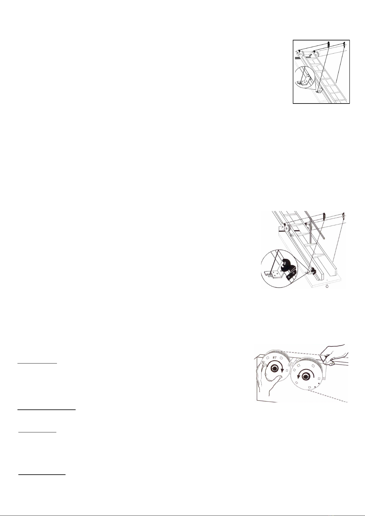
Step 25 : Adjusting Spring Drum Tension
Always work towards using the minimum amount of tension to do the job. On average, one complete
turn of the drum will add or reduce approximately 900g (2lbs) of lift.
Have enough tension for minimum force to slide the stairs up to the stored
position, but not so much that the stairs creep up when resting on the floor.
This could cause accidental tripping. Too little tension may allow the stairs
to feel heavy.
Door Panel Tension
The door should close very slowly without slamming, but with enough tension to hold the door against the stops.
by adding more turns of cable. Take the end of the cable loose from the cable holder and
slowly let it wrap up on the drum. While you still have a length of cable in your hand, hold the drum
firmly and wrap additional cable around the drum as needed. Return cable to holder.
Repeat for other side.
Reduce Tension by unwrapping additional cable. Take the end of the cable loose from the cable holder
Stair Tension
Add Tension
and slowly let it wrap up the drum. Hold the drum firmly and unwrap additional cable from the drum as
needed. Return cable to holder and repeat for other side.
WARNING
DO NOT LET CABLE SLIP FROM YOUR HAND AS SUDDEN RELEASE OF TENSION CAN
BREAK OR BACK-WIND THE SPRING AND CABLE TRAVEL MAY CAUSE PERSONAL INJURY
WARNING
DO NOT LET CABLE SLIP FROM YOUR HAND SINCE SUDDEN RELEASE OF TENSION CAN
BREAK OR BACK-WIND THE SPRING AND CABLE TRAVEL MAY CAUSE PERSONAL INJURY
8

TROUBLESHOOTING
What should I do if the stair
section is jumping out of track?
What should I do if the stair
section is hard to move or
binding?
What should I do if thecable runs
off of the drum when moving stair
section?
What should I do if the stair
section comes down too fast?
What should I do if the stair
section 'creeps up' from the down
position?
What should I do if the
door panel fails to close?
What should I do if the door
panel slams shut?
What should I do if the spring
drum breaks or back winds?
Reduce spring tension to string drum (no. 8). Refer to step 25.
Check the width of the stairs and check the dimensions between the
slide bars. You may adjust the slide bars by bending the bracket slightly
in or out as needed - please see table A.
Make sure slide bars are in the guide channel over the entire length of travel
Lubricate guide channel with silicone grease Look for gouge marks and check
width of stairs at that point (see table A) Check seating of treads.
Check to see if the stair is centred in opening Check for proper alignment of
hardware Check for alignment and plumbness of frame Mounting brackets
can be shimmed to correct minor mis-alignment.
Add spring tension to string drum (no. 8). Refer to step 25.
Add spring tension to panel drum (no.7). Refer to step 25 Make sure
screw heads are seated against hinge Check for foreign debris.
Reduce spring tension to panel drum (No.7). Refer to step 25.
Please contact your supplier.
Units C & D, Ford Lane Industrial Estate, Ford, Arundel, West Sussex. BN18 0DF
t: 0845 676 0704 f: 0845 676 0705 www.loftcentre.co.uk
Model Slide bar inside
width
Ladder outside
width. (+/- 2mm)
400 422mm 433mm
700 468mm 480mm
Table A
WARNING
The Spring inside the drum, even IF broken or
back-wound is under EXTREME compression
NEVER OPEN THE SPRING DRUM
Please contact your supplier.
9
This manual suits for next models
1
Table of contents
Other Loft Centre Ladder manuals
Popular Ladder manuals by other brands

Primal Vantage
Primal Vantage MNSL-120 Instruction and safety manual

Berner
Berner TOPline 144787 Instructions for use

Safelincs
Safelincs EvacSill user manual

EXTOL PREMIUM
EXTOL PREMIUM 8849005 Translation of the original user manual

Branach
Branach FPE-AT 1.2 User instructions

OUTILS OCEANS
OUTILS OCEANS MAGIC-REBOARD user guide

FVC
FVC ProMaster PM0201B installation guide

Sealey
Sealey LAD004 quick start guide

Stromberg Carlson Products
Stromberg Carlson Products LA-401 quick start guide

W+W
W+W TRI-KLAPP 95 Mounting instruction

Confer Plastics
Confer Plastics 635-52 Assembly and instruction manual

Batavia
Batavia PROFESSIONAL BT-TL014W operating instructions