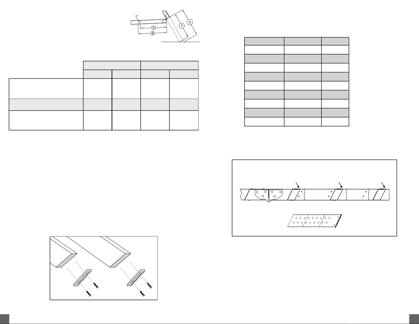
APPENDIX – Framing A Rough Opening Parallel To Ceiling Joist
Make a rough opening to the size as
required in table 1 ensuring that the
dimensions of the diagonals of the frame
are the same as illustrated in Figure 18.
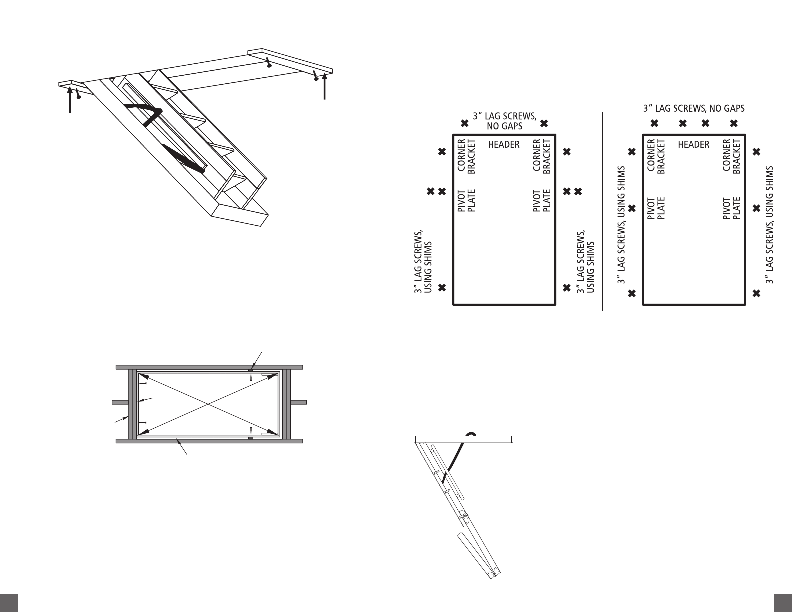
A. For Rough opening without joist
removal (Figure 18)
• Locate headers in front and rear of the
opening as shown in Figure 18.
• Check for squareness by making sure
that diagonal measurements are
within ⁄”.
• Secure using (3) 16d nails into each end
of the Header.
FIGURE 20
Headers
Headers
Nails
Diagonal
Measurements
Stringer
Customer service: 1–800–666–2811 or e–mail info@louisvilleladder.com
Servicio al cliente: 1–800–666–2811 or e-mail info@louisvilleladder.com
11
ADVERTENCIA
Antes de empezar la instalación de su nueva escalera de ático plegable para montaje en el techo
Louisville, debe leer y entender lo siguiente:
1. Solo para uso residencial, no para uso de establecimientos comerciales o industriales.
2. La instalación requiere 2 personas
3. Favor de NO remover los cinchos de plástico que aseguran las secciones de la
escalera hasta que se indique.
4. Revise que la altura del techo no sea mayor que el largo de la escalera. Si la escalera es muy corta,
regrésela al punto de venta y cámbiela. Bajo ninguna circunstancia la escalera de ático plegable se usará cuando
la medida del techo al suelo exceda la máxima altura permitida como se indica en la escalera que está instalando
(Véase la columna de rango de altura de techo en la Tabla 1)
5. La escalera de ático plegable se encuentra completamente ensamblada y lista para instalación. Favor de no
desensamblar para instalar
6. Los pistones de gas / resortes ubicados en la escalera de ático plegable se encuentran bajo presión, por ninguna
circunstancia remueva o remplace antes de la instalación.
7. Antes de instalación, confirme que todos los componentes de ensamble se encuentren apretados. Revise
periódicamente después de la instalación.
8.Asegúrese que no haya cables o tuberías con los que la sierra o el taladro puedan tener contacto durante la instalación.
9. No abra o pise en la secciones de la escalera de ático plegable antes de estar apropiadamente sujetas a las vigas
del techo, ya que hacerlo podría causar serias lesiones corporales.
10. Asegúrese de que la unidad cumpla con los códigos locales de construcción y que la zona prevista para la
instalación la escalera cuente con la suficiente fortaleza para ser utilizada como área de transito o de trabajo.
11. Si la casa tiene vigas, no las corte sin antes consultar a un ingeniero para su aprobación.
12. Antes de la instalación, lea todas las etiquetas en la escalera de ático plegable.
13. La instalación inapropiada de la escalera puede causar serias heridas.
14. No intente abrir la puerta antes de ser instalada.
15. Para la instalación de la escalera use las pijas de cabeza hexagonal provistos para la etapa de instalación permanente.
16. Siga las instrucciones “AJUSTE EL LARGO DE LA ESCALERA”en el paso 3 para las instrucciones adecuadas de corte.
17. Lubrique anualmente las bisagras izquierda y derecha del brazo mecánico plegable (brazo de poder) para
proporcionar una suave, larga y duradera operación. Se recomienda silicón en spray.
12