Logan Graphic Products F500-3 Manual

INSTRUCTION MANUAL MODEL F500-3
Deluxe Frame Finishing Kit
INSTRUCTIONS AND OPERATION MANUAL
N1328 Rev 1 09/15
LoganGraphic.com

Logan Graphic Products Inc. 1100 Brown Street, Wauconda, IL 60084 1-847-526-5515 1-800-331-6232
LoganGraphic.com
Adjustment Screw
Point Loading Cover
Point Depth Adjustment
Cover Release Button
Nose
Identification
N1329 1-15
Fig. 3
Fig. 2
3.
2.
1.
Fig. 4
3.
2.
1.
Fig. 1
Model F500-2
Dual DrivE Elite Point Driver
PICTURE FRAMING
Instruction Sheet
Operating Instructions
Loading Points
1. Press release button
2. Pull up cover
3. Install point strips with point facing
forward
NOTE:
Make sure points are inserted
down into nose piece.
4. Slide cover closed (Fig. 1)
Operation
1. Hold outside of frame
2. Press driver nose against inside frame
3. Keep drive flat on material - DO NOT
LIFT OR ANGLE
4. Squeeze trigger to insert point
5. Space points 6” apart, 3” from corners
(Fig. 2)
Adjust Point Depth
1. Turn adjustment screw to increase
tension for hardwoods or decrease
tension for softwoods. (Fig. 3)
Troubleshooting
IF GUN JAMS & NO LONGER FIRES POINTS
• Keep 1” or higher stack of points in gun at all times
• Make sure you are using authentic Logan rigid or flexible points (F53, F54, F55, F56).
• Make sure points are loaded and seated correctly. Try removing and re-loading the point strip.
• To remove a point jammed in the nose piece, reference the instructions to remove the nose piece, clear
it and re-install it.
• If point does not leave the gun, try reducing or tightening tension.
• Check to see that main body screws holding two halves of the tool together are not loose. If necessary,
re-tighten with Phillips screwdriver.
IF THE POINT BENDS
• If flexible inserts are bending or not staying in the wood, try increasing the tension or switch to rigid
points.
• Try reducing the tension if handle is hard to pull.
Point Jammed
1. Remove points
2. Remove nose screw and nut
3. Remove nose piece and discard
jammed point (Fig. 4)
Replacement Points
Use only authentic Logan Points
F53 - Flex (600) F54 - Rigid (600)
F55 - Flex (2500) F56 - Rigid (2500)

Operating Instructions
Blade install: (Fig. 1)
1. Determine right hand or left hand usage.
2. Remove nut and three (3) blades.
3. Separate and install one blade, sharp edge down.
4. Slide cover to “safe” when not using and “blade” when ready to use.
Apply dust cover:
1. Using double sided tape , ATG tape or glue, apply continuous line around
back of frame about 1/8” from edge (Fig. 2)
2. Cut a piece of Kraft paper (30, 40, or 50 lb available at craft stores) that
is larger than overall outside of frame by a minimum of 1”.
3. Lay paper flat onto table and drop the frame straight down onto the
paper with taped side down and artwork side facing up. (Fig. 3)
4. Using water in a spray bottle, completely dampen Kraft paper evenly. As
water dries, the paper will shrink tight. (Fig. 4) NOTE: Use a hairdryer to
decrease drying time.
5. Crease paper along the edges of frames (Fig. 5)
6. Using trimmer, start beyond edge of a corner, hold on slight angle up
against frame edge. Draw trimmer along edge to trim. (Fig. 6)
7. Repeat for other three sides.
Model F60
DUST COVER TRIMMER
L2222 01/15
Fig. 4 Fig. 5
Fig. 1
Fig. 2
Fig. 3
PICTURE FRAMING
Instruction Sheet
Fig. 6
Logan Graphic Products Inc. 1100 Brown Street, Wauconda, IL 60084 1-847-526-5515 1-800-331-6232
www.logangraphic.com
Sharp Edge
Artwork Side Up
Left hand
usage
mount
side
Right hand
usage
mount side

Several options exist for hanging your artwork, but the general method utilizes picture hanging wire because it provides the greatest ease and flexibility with artwork
of any size. In recent years, strap hangers with D‑rings have grown in popularity over screweyes, because they lie flat against the back of the dust cover and won’t
scratch the wall.
Installing D-Rings
To position D‑Rings, measure about one‑third down from the top of the frame and mark the location. Do this on both sides. Nylon‑coated hanging wire comes in
three strengths: 19 lb., 25 lb. and 43 lb. Each strength is a measure of the weight‑bearing capacity of the wire. If the framed piece is too heavy for the wire, the wire
will unravel, pulling free of the hangers, regardless of the complexity of the knots used.
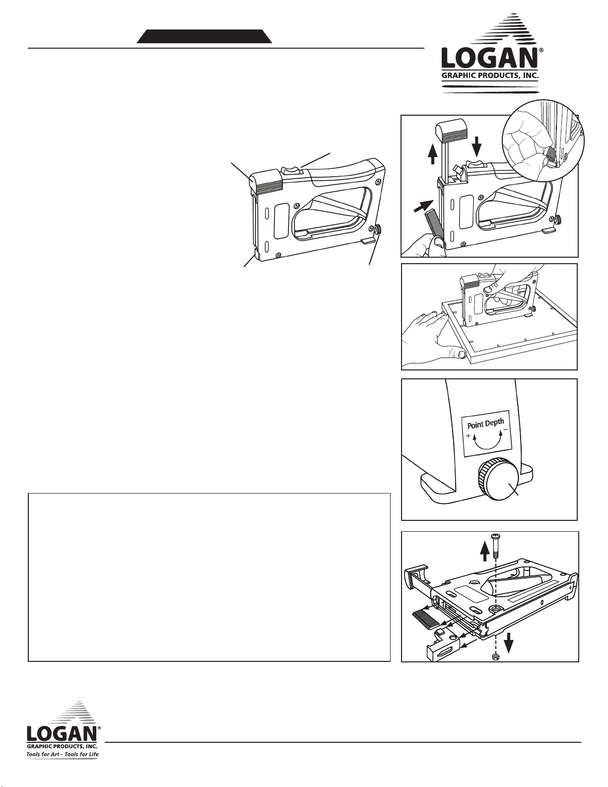
To attach D‑Rings to soft or medium wood frames,
make a pilot hole in the back of the frame with a
scratch awl. Turn the screw into the wood with a
screwdriver (Fig. 1). To attach a D‑Ring into hard‑
wood frames, drill a hole with a power drill and attach
the screw with a power screwdriver (Fig. 2).
Fig.1
Fig.2
Installing Wire
To install the wire, insert one end
through the D‑Ring allowing 3‑5 inches
of wire to feed through, twist it around
itself and loop it through the D‑Ring
one more time. Pull tight and then coil
the excess around itself keeping the coil
tight and cutting away any excess after
finishing. (Fig. 3)
Stretch the wire across through the other
D‑Ring allowing 3‑5 inches of excess, use
a finger to pull up slightly in the center of the wire to create some slack in
the middle of the wire and repeat the tying and coiling process. (Fig. 4)
Attaching Bumper Pads
For a nice finishing touch, attach self‑adhesive bumper pads to bottom corners on the back of your frame.
These will prevent the frame from scratching the wall, allow air circulation behind the frame to help prevent
any condensation and allow some light behind the frame to help prevent fading of wall paint color. (Fig. 5)
Fig.5
N1328 Rev 1 09/15
Logan Graphic Products Inc. 1100 Brown Street, Wauconda, IL 60084 1‑847‑526‑5515 1‑800‑331‑6232
www.logangraphic.com
Installing Hanging
Wire and Bumper Pads
PICTURE FRAMING
Instruction Sheet
Fig.3 Fig.4
Table of contents
Popular Nail Gun manuals by other brands

Hitachi
Hitachi NR90GC - 3-1/2" Gas Powered Clipped Head Framing... Technical data and service manual

porter cale
porter cale FN250A instruction manual

Makita
Makita AF503 parts list

Omer
Omer 4097.25 CLT Use, maintenance and spare parts manual

Senco
Senco FinishPro32 operating instructions

Bosch
Bosch FNA-250-15 Operating/safety instructions