Logiblocs Electric City User manual

INVENTOR’S MANUAL

ELECTRIC CITY KIT
INTRODUCTION
Welcome to the hi-tech world of Logiblocs!
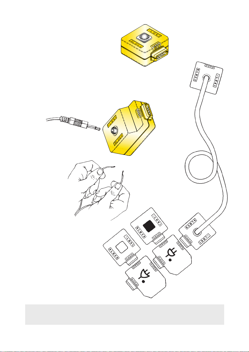
These instructions will tell you all you need to know to make a Door Alarm,
Security Mat, Water Bleeper, Light Detector, Light Breaker Alarm, Treasure
Hunt and a Flash Back unit.
You may already have other Logibloc kits and, if so, you will be able to com-
bine the Logiblocs in this kit with your other kits to increase their power and
flexibility.
If you join the Logiclub you will be able to get loads more ideas of things to
make and do with your Logiblocs. You may try to win a prize by entering
your own ideas in the regular competitions. See us at www.logiblocs.com
SAFETY
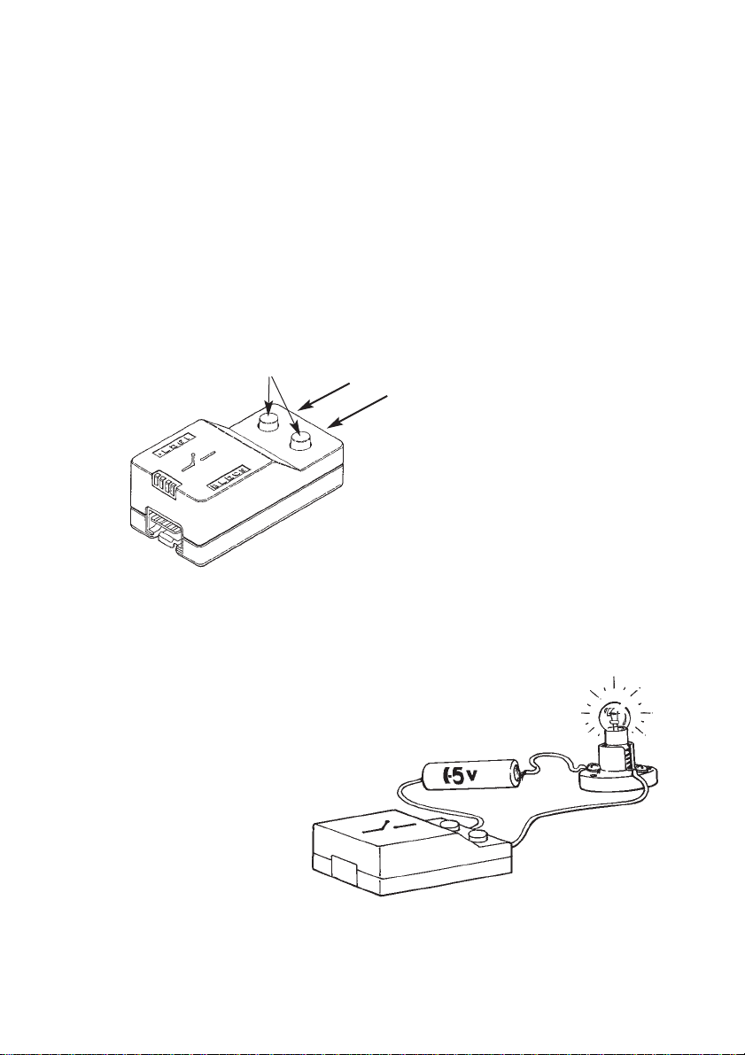
Logiblocs are absolutely safe if used correctly. Please read the section on
safety at the end of this booklet. Do not use the Logiblocs until you under-
stand the safety advice. Please keep these instructions for future reference.
Never ever touch or try to push any wires into a mains electrical socket or
plug. This would be very dangerous. Do not let the Logiblocs get wet and
never put any parts or wires into your mouth.
LOOKING AFTER YOUR LOGIBLOCS
It’s a good idea to keep your Logiblocs in the box. There is plenty of space
underneath the plastic holder to store your models and any Logibloc
Extrablocs you may have.
Remember that Logiblocs are very special and need to be looked after well.
Keep them clean and try not to step on them!
THE LOGIBLOC GUARANTEE
If by any chance anything is missing or not working properly, please write to us
at the address on the back of this booklet and we will sort things out as soon as
possible. This does not affect your right to return this product to where you bought
it from under the retailer’s usual terms and conditions.
2

UNDERSTANDING LOGIBLOCS
Logiblocs make computer technology simple!
Logiblocs is the electronic discovery system that helps you understand about
the world of technology around you as you create your own inventions.
From traffic lights to super computers, everything in today's high-tech world
runs by the same principles that Logiblocs demonstrate. Inside each
Logibloc is a printed circuit board and every block is colour-coded for the
function it performs. By plugging together Logiblocs in different combinations
you can create circuits and virtually write your own simple program to build
each new invention.
Each block has its own job to do, described by its colour:
Logi Yellow
Input: These blocks trigger the system at the press of a button and in all
sorts of other ways.
Logi Blue
Throughput: These blocks take messages from place to place.
Logi Orange
Logic: These brain blocks do the thinking and make sure that everything
happens in the right place and at the right time.
Logi Red
Output: These chatterboxes turn things on and off and communicate with
the outside world through light and sound.
Logi Green
Power: These energy suppliers give life to Logibloc inventions.
All Logiblocs work with each other so with a few Extrablocs you can build on to
your inventions to make them even more powerful using your Logimagination.
3

CONTENTS
Please check that you have all the parts in the Electric City Kit as follows:
BATTERY BOX
BUTTON
IN
LIGHT SWITCH
NOT
AND
OR
BLEEP
OUT
STRAIGHT (x 4)
CROSS (x 2)
FLYER
Jack Plug, Wires (Red,Yellow & Blue)
Bulb (1.5V) & Socket, Stickers
4
Maximum current rating 1A

LET’S GET STARTED
The first thing to do is to get to know the Logiblocs and make sure that they
are working OK.
You will need four 1.5V AA (LR6) size batteries.
Step 1
Open the BATTERY BOX and put
the batteries in. See the section on
battery installation near the end of
this booklet.
Step 2
Plug in the BATTERY BOX
to the CROSS
Step 3
Plug in the BUTTON and BLEEP.
When you press it the light on
the CROSS should come on
and the BLEEP will sound.
If this doesn’t happen,
check that the batteries
are put in correctly.
If you still have trouble,
maybe your batteries are flat!
BATTERY
BOX
CROSS
BLEEP
BUTTON
5

Step 4
Put the Logiblocs
together as shown.
The NOT will be on showing how
it always does the opposite to the
other Logiblocs!
Now press the BUTTON and see what
happens. The NOT should go off
and all the other lights
will come on.
Also, listen for the click of the OUT.
This is the relay inside which completes
the circuit between the two terminals.
STRAIGHT
NOT
OUT
6

Step 5
Replace the BUTTON with the
LIGHT SWITCH. The lights will
come on again. Now cover
over the LIGHT SWITCH with
your hand and see what happens.
Step 6
Replace the LIGHT SWITCH with the IN
and plug in the Jack Plug leaving
the two wires loose.
Step 7
Finally, just add the FLYER,
AND, and OR Logiblocs,
press the BUTTON and check
that all the lights work.
Hold the Jack
Plug wires
in each hand
and touch
the metal ends
of the wires
together.
Again the lights
will light up.
As you have
seen, there are
three different ways to
trigger the Logiblocs.
LIGHT
SWITCH
JACK PLUG
IN
7
You have successfully completed the test procedure. Well done!
Now it is time to get the Logiblocs to work and have some fun!

LET’S GET THE LOGIBLOCS TO WORK
As you have seen, using the IN and joining the two wires from the Jack Plug
together, you can trigger the Logiblocs into action. We will now use this sys-
tem to make the Door Alarm, a Security Mat and the Water Bleeper.
❶DOOR ALARM
You will need a small strip of aluminium foil and some sticky tape.
Step 1
Take the two wires and place
them near the bottom of the
door surround with their ends
sticking out so that the door will
brush past them when it is
opened. Stick the two wires
on with sticky tape.
Stick your “Alarmed” sticker on the door to tell people that you are alarmed!
Don’t forget to disconnect the BATTERY BOX when you are not using the
Logiblocs to make the batteries last as long as possible!
8
Step 2
Shape a strip of aluminium foil
around the edge of the door
itself, at the height of the two
wires. When the door opens,
the aluminium foil will touch
both wires which should trigger
the Logiblocs into action. This
is called completing the circuit.

Step 3
Fix the Logiblocs together
as shown.
This circuit is called the Memory Circuit
because it captures the signal from the
IN however short it is. Press
the BUTTON to re-set
the system.
Hide the Logibloc system
you have made. Remember, if
you want, you can extend the jack
plug wires just by joining two other wires on
to make them longer. Make sure you cover the
joins with tape to avoid accidentally
setting the alarm off!
9

Step 4
Now you have made the Memory Circuit and your sensor on your door you
will need to check that the system is working OK. Open the door and make
sure the system is triggered. Remember that the Memory Circuit will capture
even the shortest trigger. Have fun!
Step 5 (Optional)
When your door alarm is working really well it could be time to add to the
system. The Logiblocs can also turn on other things such as motors and
lights using the OUT. Add the OUT on to your system and check that it
clicks when you open the door. This clicking is the sound of the relay
inside completing the circuit between the two terminals.
Note, the OUT does not provide any power output itself, it just
completes the circuit. You will need a separate battery supply
to drive any lights or motors that you want the Logiblocs
to control. Maximum current rating 1A.
Try fixing up the bulb and socket so that
the light will shine when the door is
opened as well as or instead
of the BLEEP alarm. You will
need a 1.5V AA (LR6)
battery and three wires.
Keep the Memory Circuit you have made fixed together and store it carefully
in the Logibloc box. You will use it time and time again!
10
TERMINALS WIRES GO
IN HERE
To join wires to the terminals,
simply push down the knob,
insert the bare metal end of
the wire and let go of the knob.
The terminal will grab the wire
and hold it firmly.
1
2
3

❷SECURITY MAT
You will need some aluminium foil, scissors, paper glue, some cardboard
and some sticky tape. You can use the piece of card provided but you may
prefer to keep this for use as an attractive mouse mat!
Step 1
Cut out two pieces of card or cardboard 20cm x 15cm.
Stick two pieces of aluminium foil to one side of each
piece of card. Cut out four strips of cardboard
to go right around the edge of
one piece of card.
Step 3
Join the blocks together as shown for the Door Alarm and plug in the Jack
Plug. Tap the sandwich you have made. When the two pieces of foil touch,
the circuit is completed and the Logiblocs should be triggered. If the aluminium
foil sheets in the sandwich are touching too easily then add another spacer
or two. When you are happy with the sandwich, stick down the top piece of
cardboard to the spacers.
Hide the Logiblocs and place the mat under carpets and surprise your
friends when they step in the wrong place! Remember to disconnect
the BATTERY BOX when you are not using the Logiblocs
to save the batteries!
11
Step 2
Stick one of the wires to the corner of
the foil with sticky tape. Glue the strips
of cardboard around the edge to form a
spacer. Stick the other wire to the
corner of the foil on the other card.
Place (do not stick) the second card
on top of the spacer to make
a sandwich.

❸DRAWER GUARD
You can fix up your special
drawer using some aluminium
foil as shown. If the drawer is
opened the aluminium foil will
brush past the two metal ends
of the Jack Plug wires so com-
pleting the circuit and setting the
alarm off.
Hide the Logiblocs at the back or beside the drawer where there is usually a
bit of space.
❹CHECK FOR METAL!
We can use the two metal ends of the Jack
Plug Wires to test for metal. Metal con-
ducts electricity and so you can test all
sorts of objects. Use the same Logibloc
arrangement shown on opposite page. Test
a pencil. Does the lead inside conduct
electricity? So it’s not just metal that
conducts electricity. Your message should
be “Look! I conduct electricity!”
Remember not to put these wires anywhere near any mains electrical outlets
because that could be very dangerous.
12

➎WATER BLEEPER
You will need two pieces of aluminium foil and some sticky tape.
Step 1
Make two square sheets of
aluminium foil about 10cm x 10cm.
Stick the Jack Plug wires to the top
of each aluminium foil sheet.
Step 2
Join the blocks together
as shown.
Connect the BATTERY BOX
and plug in the Jack Plug.
Step 3
Place the Logiblocs on the edge of a basin but be careful
not to get them wet! Fill up the basin to half full.
Hold the two aluminium foil sheets one
in each hand but do not let them touch
and slowly lower them in to the water.
The BLEEP should go off since the
water acts to complete the circuit.
Now experiment with the water sensor to find other ways
to let water trigger the Logiblocs. Fix the sheets to the side
of the bath to warn you when it has reached the right level!
13

LIEDETECTOR
We can use the Spy Kit to make a Lie Detector.
This uses the effect that when people do not tell
the truth they usually sweat which increases the
electrical conductivity of their hands.
Step 1
Make two hand sized aluminium foil
pads and lay them side by side on a table,
making sure that they do not touch. Fix with tape the
metal ends of the Jack Plug wires with some sticky
tape, one to each piece of foil.
Step 2
Put the blocs together as shown and plug in the Jack Plug
into the IN block.
Step 3
Now keeping the pads separate, place one or two fingers
on one pad. Get someone to ask you some questions
about you or your friends. Each time you give either a true
or false answer put one or two fingers from your other hand
onto the second pad. The sound level of the BLEEP will
change depending on how hard you press or how much your
hands are sweating (because of telling lies!).
You can also do this with two people. Put
your right hand on the right pad while your
friend puts his or her left hand on the left
pad. Ask each other questions and then join
your free hands together. You will find that
the Logiblocs can be triggered through you
both! This is because your bodies also can
conduct electricity.
14

LET’S MAKE SOME MORE MODELS
As you have seen, light shining into the lens of the LIGHT SWITCH can
trigger the Logiblocs into action. There are lots of different ways that you
can use this to make things either turn on or off by just shining a light at
the Logiblocs. We will now use it to make a Light Detector unit and the
Light Breaker Alarm. Also we’ll show you how to play the Treasure Hunt
in the dark!
❶LIGHT DETECTOR
Step 1
Fix the Logiblocs together
as shown.
Have fun! Don’t forget to disconnect the BATTERY BOX when you are not
using the Logiblocs to make the batteries last as long as possible!
Walk around in the evening and
see when the green light is on and
when the red light is on. Swap
round the BLEEP so that it only
goes on when there is no light.
Try shining a flashlight at the
Logiblocs from a distance.
Test your target practice by
aiming the flashlight at the
Logiblocs before you turn
it on. If the BLEEP
bleeps you’re on target!
15

❷LIGHT BREAKER ALARM
You will need a flashlight to make the light breaker alarm.
Find a dark spot or wait until the light is fading.
Step 1
To make sure that we catch the intruder,
we need to use the Memory Circuit again,
although in a slightly different way.
Step 2
Fix the LIGHT SWITCH to
the wall and line up a flashlight
to shine across the room at the lens.
If anyone crosses the light beam,
the alarm goes off.
Plug the Logiblocs
together as shown
and stand them up on
the BATTERY BOX.
16

Step 3
Experiment with the best place to put the
Logiblocs and the flashlight. Re-set the alarm by
pressing the BUTTON. Guard your room so that
no-one can get past without setting the alarm
off! Why not fix it up using mirrors?
❸FLASH BACK
Step 1
Plug the Logiblocs together as shown.
Step 2
Connect the light bulb circuit to
the OUT terminals as shown
in Step 5 of the Door
Alarm (page 10).
Step 3
Cover the lens and the
bulb will shine.
Now bring the shining bulb close to the
lens until it is almost touching. See
what happens.
This is called feedback.
Try replacing the LIGHT SWITCH with the
IN and connect the jack plug wires directly to
the terminals of the OUT.
Remember to disconnect the BATTERY BOX
when you are not using the Logiblocs to save the
batteries!
17

❹TREASURE HUNT
Plug the Logiblocs together as for the Light Detector unit (page 15). Remove
the NOT. Hide the Logiblocs behind things in a dark room. Do not cover
the lens of the LIGHT SWITCH and make sure that the flashlight will trigger
the Logiblocs when it is shone directly at the hidden LIGHT SWITCH.
Take it in turns to hide the Logiblocs in ever more clever places. Hide the
Logiblocs in secret places and see the hidden treasure revealed with the
shine of your flashlight!
➎ LOGIBUZZER
We can use another type of feedback loop to
make a Logibuzzer.
Put the blocks together as shown.
Connect the Jack Plug wires to the
terminals of the OUT block. Plug the
Jack Plug into the IN. If there is enough
light shining onto the LIGHT SWITCH
the blocks will buzz.
Now cover the lens of the LIGHT
SWITCH with a loose Logibloc
and the buzzing will stop. If any-
one takes the loose block away
the alarm will sound again.
What happens if
you swap the AND block
with the OR block?
18

WHAT THE LOGIBLOCS DO
BATTERY BOX
(6V output. 4x1.5V AA LR6)
This brings the power from the
batteries to make the Logiblocs
work. Plug it in to a CROSS or
wherever there is a space.
CROSS
This acts as a cross-roads
for all Logiblocs and lets
you turn corners.
STRAIGHT
This is the basic Logibloc piece
that just gets you from place to
place.
The light lights up whenever
it receives a message and it
passes it on immediately.
BUTTON
When the button is pressed it
triggers any block connected
to it.
The button is the easiest way
to turn things on.
19
Logiblocs
make things
happen
!

IN
Plug in the Jack Plug. When the two
wires of the Jack Plug are joined
together the IN block triggers any other
block that it is connected to.
OUT
The OUT is triggered by any other block
which is connected to it. Plug a wire
into each of the two terminals by
pressing down on the knob, inserting
the wire and releasing the knob which
will hold the wire firmly.
When the OUT is triggered it closes the
circuit between the two wires which can
make other things work such as light
bulbs and motors which will need their
own power supply.
Maximum current rating 1A.
NOT
This does the opposite of what you
expect. When it gets a message it
doesn’t send it on and if it has no
message it sends one of its own!
WHAT ELSE THE LOGIBLOCS DO
20
Logiblocs
let your
imagination
go!
Table of contents
Other Logiblocs Toy manuals