6
2.5.2 Operation device of component parts
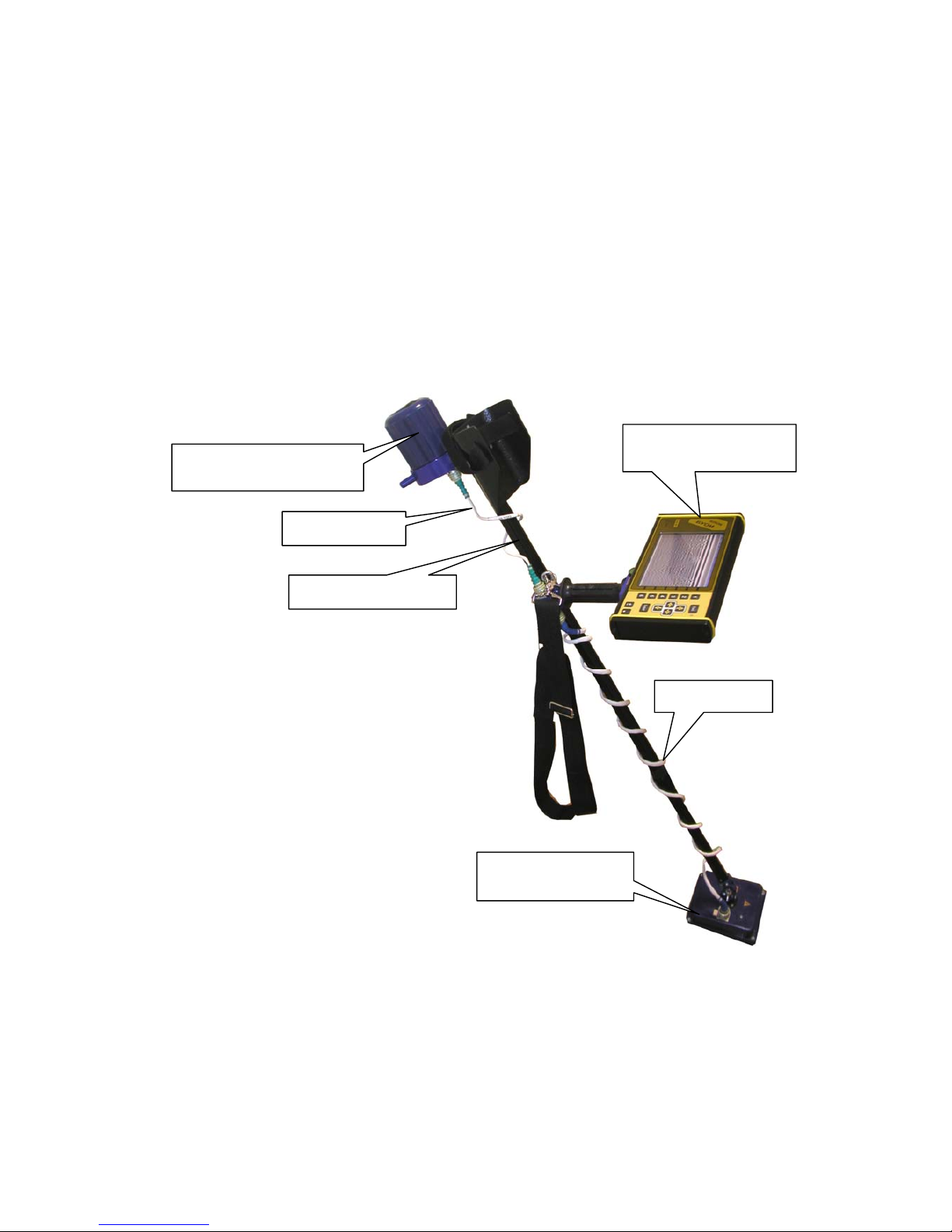
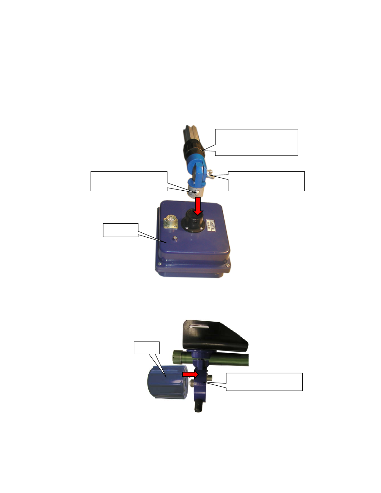
Receiving and transmitting antenna unit (BAPP)
Receiving and transmitting antenna unit functionally consists of receiving, transmitting units
and receiving and transmitting antenna unit with volumetric damping resonator.
Receiving unit
The receiving unit functionally consists of receiving antenna unit, the scan stroboscopic device,
selection and storage device (SD) and the control unit.
Reflecting from the inhomogeneity in the tested environment the signals are coming from input
receiving antenna unit to output SD, where they are stored at the time of processing. The signals are
coming from SD to the analog digital converter (ADC). The microprocessor receives the transferred
digital signal. The control unit is to realize the preliminary processing of the received data and to
transfer the data to the BUOI.
The signals for start of the transmitter are to form in the control unit and are to transfer to the
transmitting unit.
The scan stroboscopic device is to form the pulses for the SD operation. The selection and
storage unit is to remember the signal by control pulse and is to store it more than 1 micro second. It is
enough time for ADC to transfer the processed analog signal to a digital code. BAPP II is to operate in
the range, where the frequency ranges ADC are to allow the transformation of analog signals into the
digital code without using SD. So for the range of BAPP I the signals from input of receiving antenna
unit are coming to output of ADC.
The sensitivity of the receiving device is not worse than 300 microvolt.
Transmitting unit
The transmitting unit functionally consists of transmitting antenna unit, pulse shaper and high
voltage-power supply unit. The pulse shape at receipt of the starting pulse are to form the (короткий
перепад high voltage) which is to activate the transmitting antenna. The high voltage power supply
unit is designed to transform the voltage of 12V into power which is necessary for operation the pulse
shaper. (duration of a pulse of 1,5-2,2 nanoseconds with fronts up to 0,2-0,3 nanoseconds and
frequency of following 200 KHz.)
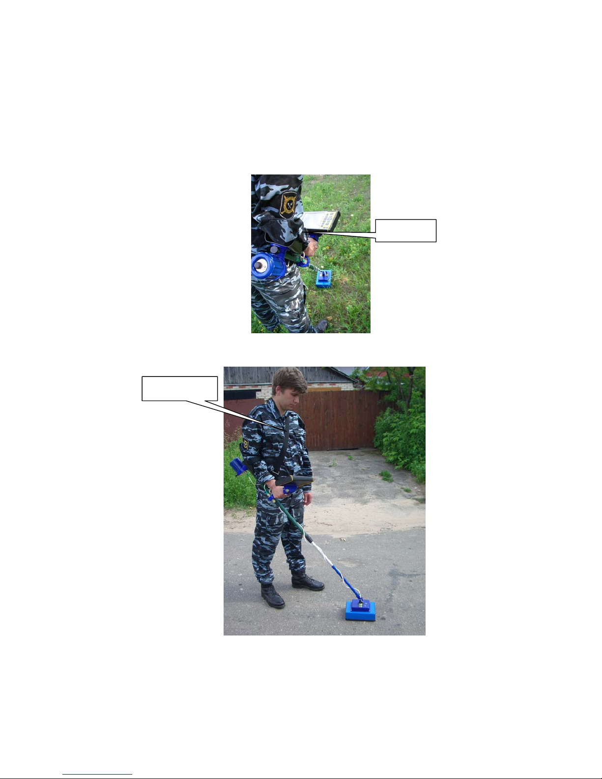
The control, processing and indication unit (BUOI)
The control, processing and indication unit is based on the digital signal processor and
functionally consists of all climatic liquid crystal indicator, the control device and the keyboard. All
operations are realized using the buttons located on the front panel. Using the buttons the operator is to
choose the required points or parameters in menu which are displayed on the indicator and is to change
them according with the required task.
According with the choice of the mode and parameters, the control device is designed on the
signal processor, forms instructions and transfers them to the antenna unit (BAPP) using interface RS-
485.
The accepted data are processed and displayed on the screen.
BUOI has the high definition (640x480 points) liquid crystal color display.
BUOI allows to keep the received data in the memory 1Gb (this size of memory is sufficient
for storage approximately 240000 paths), that at the step of scanning 5 cm is about 12000 m of a
continuous profile