manuals.online logo
Brands
  1. Home
  2. •
  3. Brands
  4. •
  5. LogiCO2
  6. •
  7. Measuring Instrument
  8. •
  9. LogiCO2 0486 User manual

LogiCO2 0486 User manual

User Manual
0486 Power Monitor
ENGLISH
Power Monitor for LogiCO2 Safety System.
Important!
Retain this instruction manual for future
reference: Please read these instructions
carefully prior to start-up and use. Failure to
follow any of these instructions could void
product warranties. LogiCO2 assumes no
responsibility for claims arising out of improper
or careless use or handling of it’s products.
Technical specifications
Power supply
- Safety System: 24V DC
- Batteries: 2 x AAA Alkaline
1,5V batteries*
Internal battery check: Once per hour
Low power trig point: 18V
No power trig point: Approx 3V
Wiring connections: RJ 45
Acoustic signal-strength: ~80 dBa (1m)
Operating temperature range: 0 to +45°C (32 to
+113°F). Only for
indoor use.
Overvoltage: Category II
Pollution degree: II
Dimensions (LxWxD): 90 x 161 x 38 mm /
3.5” x 6.3” x 1.5”
Ingress protection: IP54
*NOTE! Do not use Lithium batteries or rechargeable
batteries.
Function
The Power Monitor is a surveillance unit which ensures
that the personnel are alerted in case there is a power
failure that puts the LogiCO2 Safety System out of
function. It has a built-in buzzer and place for two AAA
alkaline batteries (batteries included).
If there is a power failure the Power Monitor makes an
alarm. The Power Monitor will sound the buzzer for at
least 12 hours.
If the LogiCO2 Safety System is powered via a UPS
power back-up, it is recommended to install a Power
Monitor that monitors the UPS-function. In case the
UPS’s batteries run out, the Power Monitor will give
an alarm informing that the LogiCO2 Safety System is
out of function.
The three LEDs show the current status:
LED and sound
indication
Information
Green LED
Continuous LED-light
The Safety System has
power
Red LED
Continuous beep and
LED-light
No power to the Safety
System
Red LED
Double beep and LED-
flash every other second
Power below 18V to the
Safety System
Yellow LED
Beep and LED-flash
every five seconds
Low batteries in the
Power Monitor. Replace
the batteries.
Yearly function control
Please observe!
Since this is a safety product, we recommend that a
function control should be conducted at least once
a year. Disconnect the power to the Safety System
and check that the Power Monitor activates the “No
power” alarm buzzer and red LED. Reconnect the
power to the Safety System.
2
Installation
The Power Monitor can detect a system power failure on both the red and blue cables of the Safety System.
Mount the Power Monitor in a suitable location where it is easily seen and heard, preferably next to the Central
Unit. Do not cover the Power Monitor.
Start-up
How to start-up Power Monitor in order to avoid activating the buzzer during the start-up:
1. Install the Power Monitor in a suitable location.
2. Remove the cover by unscrewing the five Phillips-screws.
3. Disconnect the power cable installed in the Power Monitor.
4. Connect the Power Monitor, preferably directly to the Central Unit, or use a splitter and connect the Power
Monitor to the Safety Systems red or blue cabling.
5. Reconnect the power cable in the Power Monitor, and after that, install the two enclosed batteries within 30
seconds.
If the batteries are not installed within 30 seconds, the Power Monitor will activate a “low battery” alarm. The
alarm will be activated until the next battery check, which is done once every hour. To reset the “low battery”
alarm, remove the batteries and go back to step 3.
6. Reassemble the cover and screws in order according to figure 4.
Fig. 1, Power Monitor connected directly to the Central Unit of the Safety System
CO2Sensor
CO
2
Certified by UL
Ratings:24Vdc, 68mA
Madein Sweden
!
DINReg.
No:6L002
LogiCO2
Mk9
CO2Sensor
CO
2
Certified by UL
Ratings:24Vdc, 68mA
Madein Sweden
!
DINReg.
No:6L002
LogiCO2
Mk9
Certified by UL
Ratings:24Vdc, 32mA
Madein Sweden !
LogiCO2
Mk9
Gas Monitor Central Unit
Change battery
No power
!
Power Monitor
LogiCO2 International
Batteries:
2 x AAA
Replacing expired batteries
1. Rem ove the AA A batteri es.
2. Di sconnect t he power cabl e
installedin the Power Monitor.
3. Re connect th e power cable i n the
Power Monito r,a nd after th at, insta ll
bothbatteries within 30 sec.
2 3
Fig. 2, Power Monitor connected on the blue cables of the Safety System
CO2Sensor
CO
2
Certified by UL
Ratings:24Vdc, 68mA
Madein Sweden
!
DINReg.
No:6L002
LogiCO2
Mk9
CO2Sensor
CO
2
Certified by UL
Ratings:24Vdc, 68mA
Madein Sweden
!
DINReg.
No:6L002
LogiCO2
Mk9
Certified by UL
Ratings:24Vdc, 32mA
Madein Sweden !
LogiCO2
Mk9
Gas Monitor Central Unit
Change battery
No power
!
Power Monitor
LogiCO2 International
Batteries:
2 x AAA
Replacing expired batteries
1. Rem ove the AA A batteri es.
2. Di sconnect t he power cabl e
installedin the Power Monitor.
3. Re connect th e power cable i n the
Power Monito r,a nd after th at, insta ll
bothbatteries within 30 sec.
Fig. 3, Power Monitor connected on the red cables of the Safety System
CO2Sensor
CO
2
Certified by UL
Ratings:24Vdc, 68mA
Madein Sweden
!
DINReg.
No:6L002
LogiCO2
Mk9
CO2Sensor
CO
2
Certified by UL
Ratings:24Vdc, 68mA
Madein Sweden
!
DINReg.
No:6L002
LogiCO2
Mk9
Certified by UL
Ratings:24Vdc, 32mA
Madein Sweden !
LogiCO2
Mk9
Gas Monitor Central Unit
Change battery
No power
!
Power Monitor
LogiCO2 International
Batteries:
2 x AAA
Replacing expired batteries
1. Rem ove the AA A batteri es.
2. Di sconnect t he power cabl e
installedin the Power Monitor.
3. Re connect th e power cable i n the
Power Monito r,a nd after th at, insta ll
bothbatteries within 30 sec.
Manufactured by:
LogiCO2 International AB
Box 9097
SE-400 92 Gothenburg, Sweden
E-mail: info@logico2.com
Web: www.logico2.com
© 2024-01-29 R3.0 LogiCO2 HFE1163 EN
Replacing expired batteries
Always use two high performance AAA Alkaline batteries (i.e. Duracell Ultra or GP Ultra).
How to replace the batteries in order to avoid activating the buzzer during the exchange:
1. Remove the cover by unscrewing the five Phillips-screws.
2. Remove the AAA batteries.
3. Disconnect the power cable installed in the Power Monitor.
4. Reconnect the power cable in the Power Monitor, and after that, install the two new batteries within 30
seconds.
If the batteries are not installed within 30 seconds, the Power Monitor will activate a “low battery” alarm. The
alarm will be activated until the next battery check, which is done once every hour. To reset the “low battery”
alarm, remove the batteries and go back to step 3.
5. Reassemble the cover and screws in order according to figure 4.
Fig. 4, If the cover of the Power Monitor needs to be removed, please observe the following order of screw
reassambling.
1
2 3
4 5

Other LogiCO2 Measuring Instrument manuals

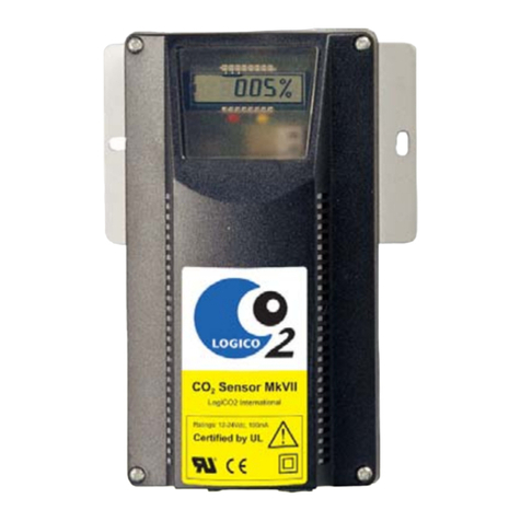
LogiCO2 MkVII User manual

LogiCO2

LogiCO2 MkVII User manual

LogiCO2 Scout Glow User manual

LogiCO2

LogiCO2 Scout Glow User manual

Popular Measuring Instrument manuals by other brands

TESTO 545 instruction manual

TESTO

TESTO 545 instruction manual

PCE Instruments PA6000 manual

PCE Instruments

PCE Instruments PA6000 manual

OHAUS MB45 instruction manual

OHAUS

OHAUS MB45 instruction manual

AST IR-CAST 2C user manual

AST

AST IR-CAST 2C user manual

Maxital M-345 user manual

Maxital

Maxital M-345 user manual

Delta DPM-C530A user manual

Delta

Delta DPM-C530A user manual

INNALABS AI-Q-2010 user manual

INNALABS

INNALABS AI-Q-2010 user manual

Bosch KMA 800 Original instructions

Bosch

Bosch KMA 800 Original instructions

Burkert 8640 quick start

Burkert

Burkert 8640 quick start

AEMC instruments 1035 user manual

AEMC instruments

AEMC instruments 1035 user manual

Spectrum Technologies 2958 product manual

Spectrum Technologies

Spectrum Technologies 2958 product manual

Megaimpulse CS-10/500 user manual

Megaimpulse

Megaimpulse CS-10/500 user manual

LANDTEC GEOTECH DIVEAIR 2 operating manual

LANDTEC

LANDTEC GEOTECH DIVEAIR 2 operating manual

Hy-Gain RBD-5 instruction manual

Hy-Gain

Hy-Gain RBD-5 instruction manual

MSW MSW-CTD-01 user manual

MSW

MSW MSW-CTD-01 user manual

PQ Plus UMD 98 Quick start manual

PQ Plus

PQ Plus UMD 98 Quick start manual

WIKA CTD9300 Series operating instructions

WIKA

WIKA CTD9300 Series operating instructions

Fluke 902 Specifications

Fluke

Fluke 902 Specifications

manuals.online logo
manuals.online logoBrands
  • About & Mission
  • Contact us
  • Privacy Policy
  • Terms and Conditions

Copyright 2025 Manuals.Online. All Rights Reserved.