GB-3
Before UseOperationSpecificationSafety Warnings Cleaning and Maintenance
Accessories
part number 673005400045
Congratulations on the purchase of your new Logik Dishwasher.
We recommend that you spend some time to read this Instruction Manual in order to fully
understand how to install and operate it.
Read all the safety instructions carefully before use and keep this instruction manual for future
reference.
Unpacking
Remove all packaging from the dishwasher. Retain the packaging. If you dispose of it please do so
according to local regulations.
The following items are included:
Measuring cup X 1
60ml (approx)
part number 673006200004
Detergent measuring spoon x 1
1 full spoon = 20g (approx.)
part number 673002200079
Water supply
hose X 1
U-shape hose holder X 1
part number 673006200003
Upper Basket x 1
Cutlery Basket x 1
part number 673002200080
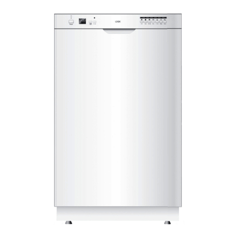
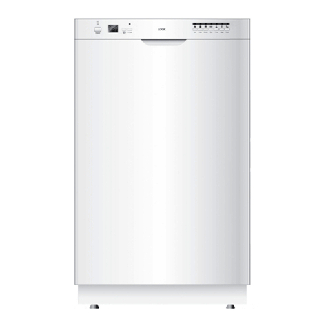
The Main Unit - Front View
Instruction
manual X 1
part number
675000608527
installation guide
X 1
part number
675000608538
• This product has been wet tested to
ensure correct operation. As a result
some water may remain inside the
unit. This is normal and safe. Remove
any water droplets from the exterior
if necessary.
Lower Basket x 1
On Delay
3in 1 Strong Normal Economy Rinse Glass Rapid
1/2
Off
20ml
Thankyou for purchasing a Logik dishwasher.
Pleaserefer to this guide for the installation process.
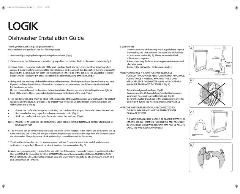
1. Removeall pack aging beforepositioning the machine. (Fig 1)
2. Pleaseensure the dishwasher is installed by a qualied technician. Refer to the tools required in Fig 2.
3. Ensurethere is clearance each side of the unit to allow slight sideways movement for servicing when
required.Good levelling is essential for correct closure and sealing of the door. When the unit is correctly
levelled,the door should not catch the inner liner on either side of the cabinet. The adjustable feet may
be loosened or tightenedin order to obtain the optimum leveling of the unit. (Fig 3)
4. If required,the worktop of the dishwasher can be removed. The height without the worktopis 820 mm.
Figure3 outlines the minimum dimensions required to accommodate the dishwasher within tted
kitchen furniture units.
Do not connect the unit to the mains beforeinstallation. Ensure you are not installing the unit right in
frontof the mains. This is to avoid potential damage to the back of the unit. (Fig 4)
5.The condensation strip must be tted to the underside of the worktop above your dishwasher to protect
it against anymoisture. Its purpose is to protect your worktop’s underside from steam rising from the
dishwasher.(Fig 5 and 6)
• Ensure the surface is clean prior to sticking the condensation strip to the underside of the worktop.
• Remove the backing paper from the condensation strip. (Fig 5)
• Stick the condensation strip to the underside of the worktop. (Fig 6)
NOTE: FAILURE TO AT TACH THE CONDENSATION STRIP COULD RESULT IN DAMAGE TO THE UNDERSIDE OF
YOURWORKTOP!
6.The worktop can be removed by removing the xing screws located atthe rear of the dishwasher (Fig 7).
After removingthe screws, lift and push the worktop forward to release the lugs from the front section of
the dishwasher.The polystyrene block and the lugs should be saved for future use.
7. Positionthe dishwasher next to a water tap and a drain. Ensure the water inlet and drain hoses are
not kinked or squashed.The unit must not stand on the mains cable. (Fig 8)
8. Make sure your plumbing is suitable for use with the dishwasher. If in doubt contact a qualied plumber.
This unit MUST BE connected to COLD WATER MAINS using the new water inlet hose. OLD HOSE SETS
MUST NOT BE RE-USED. The water pressure from the water mains needs to be at a minimum of 0.04 MPa
and a maximum of 1.00MPa.
Dishwasher Installation Guide
8. (continued)
• Connect one end of the safety water supply hose to your
dishwasher,and then connect the other end of the hose
toyour water mains (Fig A). Please ensure the black
rubber seal is in place.
• After connecting the hose, turn on your water mains and
check forleaks.
• Connect the dishwasher to the mains socket.
NOTE: YOU MAY USE A Y-ADAPTOR (NOT INCLUDED)
FOR ADDITIONALWATER FEED FOR ANOTHER APPLIANCE,
FOR INSTANCE A WASHING MACHINE. THIS IS ONLY
APPLICABLE FOR COLD WATER MAINS. A Y-ADAPTOR IS
AVAILABLE FROM MOST DIY STORES. (Fig A)
• Do not bend your drain hose. (Fig B)
• You may use the U-shaped drain hose holder to secure
yourdrain hose and to avoid bending it. (Fig C)
• Secure the water drain hose to the waste pipe to avoid it
comingo dur ing the washingprocess. (Fig 9 and D)
NOTE: THE WASTE PIPE MUST ONLY BE CONNECTED TO
THE FOUL DRAINS AND NOT THE SURFACE WATER
DRAINAGE SYSTEM.
THE WATER DRAIN HOSE SHOULD BE PLACED BETWEEN 40
CM AND 100 CM FROM THE FLOOR LEVEL AND MUST NOT
BE EXTENDED, OTHERWISE THE UNIT MAY NOT BE ABLE TO
EXPEL THE WASTE WATER PROPERLY.
Awatermains
safetywatersupply hose
C
waterdrainhose
U-shaped drain hose
holder
B
D
Y-Adaptor
(notincluded)
Connectto
another
appliance
ifrequired.
Dishwasher
Instruction Manual
LDW45S10
Logik LDW45S10_IB_100324.indd 3 3/24/10 3:24 PM
