Logitek Artisan User manual

Logitek
L
Lo
og
gi
it
te
ek
k
E
El
le
ec
ct
tr
r
o
on
ni
ic
c
S
Sy
ys
st
te
em
ms
s
A
Ar
rt
ti
is
sa
an
n
R
Re
ef
fe
er
re
en
nc
ce
e
M
Ma
an
nu
ua
al
l
R
Re
ev
vi
is
si
io
on
n
1
1.
.0
01
1
F
Fe
eb
b
2
20
00
07
7

Logitek Electronic Systems, Inc.
5622 Edgemoor Drive
Houston, Texas 77081
Tel 713-664-4470
Fax 713-664-4479
Email [email protected]
Web www.logitekaudio.com
Contents © 2007 Logitek Electronic Systems, Inc
Notice
Every effort has been made to supply complete and accurate information. However, Logitek Electronic Systems, Inc. assumes no
responsibility for its use, nor any infringement of patents or other rights of third parties, which would result.
Worldwide rights reserved. Except for your own personal use, no part of this publication may be stored in a retrieval system,
transmitted or reproduced in any way, including but not limited to photocopy, photograph, magnetic or other record, without the
prior agreement and written permission of Logitek Electronic Systems, Inc.
All trademarks acknowledged.
All specifications are subject to change without notice.

Logitek
1
Introduction
Document Revisions
Date Revision Author Notes
January 2007 1.0 Paul Dengate
Ben Hietbrink
First release of Artisan manual
February 2007 1.01 Paul Dengate Correction – Bus Numbers (p22) are 16 to 19 for MTK-MON hotkeys
Logitek Artisan Reference Manual 1

Logitek
1
Introduction
Contents
1Introduction ........................................................................................................................... 4
About this Manual............................................................................................................... 4
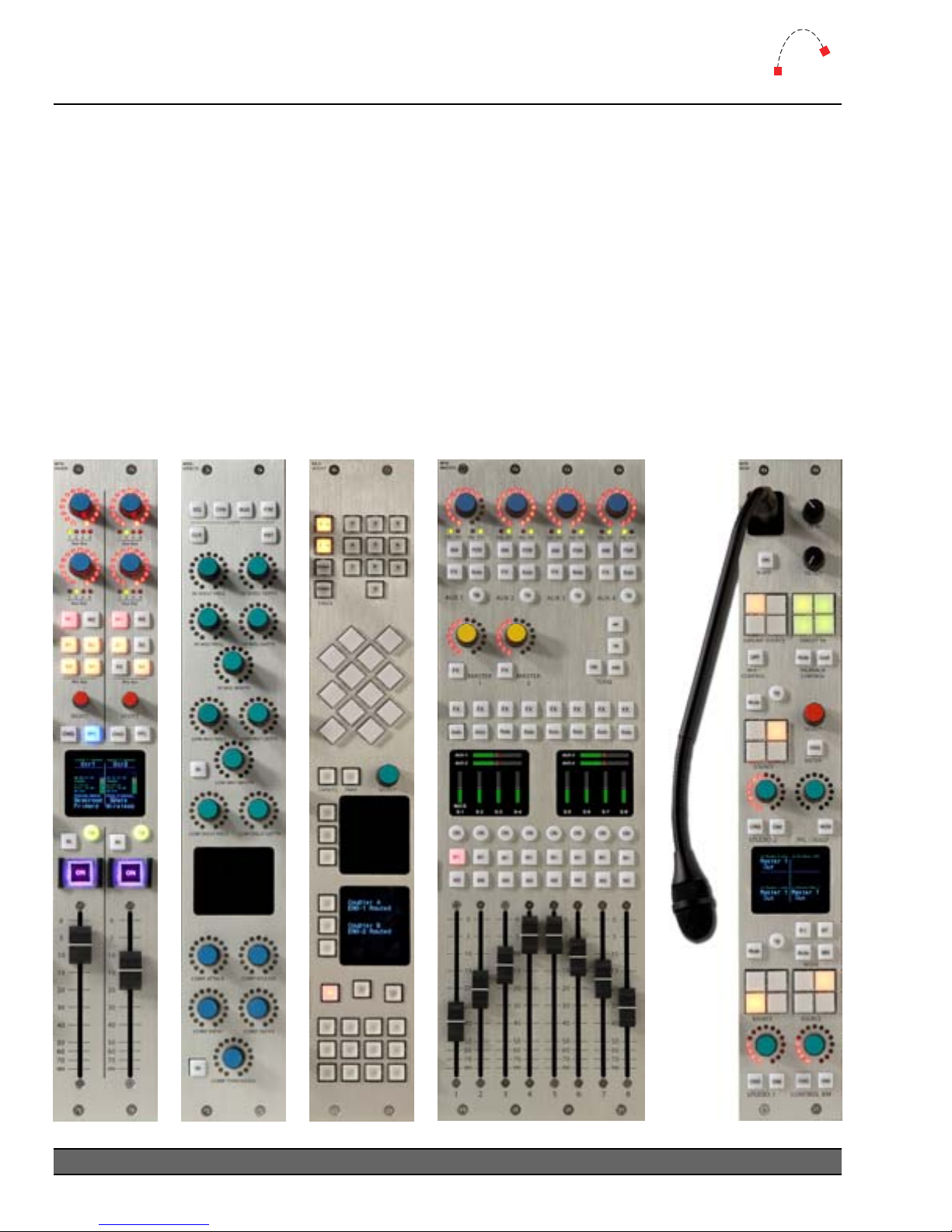
About Artisan ...................................................................................................................... 5
System Requirements.......................................................................................................... 7
2Unpacking .............................................................................................................................. 9
Parts List ............................................................................................................................. 9
Unpacking .......................................................................................................................... 9
3Physical Installation ............................................................................................................. 10
Power Supply Unit............................................................................................................ 10
Artisan Frames .................................................................................................................. 10
Artisan Cutouts.................................................................................................................. 11
vScreen Meter Bridge........................................................................................................ 14
Low Profile Meter Bridges ................................................................................................. 15
Connections...................................................................................................................... 16
4Configuration........................................................................................................................ 19
COM Port Configuration ................................................................................................... 19
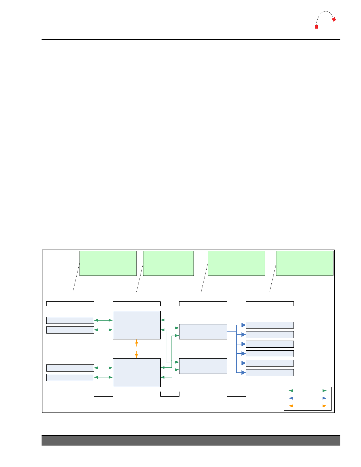
Audio Engine Configuration............................................................................................... 19
CommandBuilder Triggers................................................................................................. 19
Device & Bus Addressing .................................................................................................. 20
5Operation ............................................................................................................................. 23
Artisan Fader Modules ...................................................................................................... 24
Artisan Control Modules.................................................................................................... 28
Artisan Software................................................................................................................ 36
6Maintenance......................................................................................................................... 39
Warranty .......................................................................................................................... 39
Firmware Updates............................................................................................................. 39
Component Replacement ................................................................................................. 41
Appendix A Release Notes....................................................................................................... 44
Upgrade Strategies ............................................................................................................ 44
Current Versions ............................................................................................................... 44
Version History ................................................................................................................. 45
Known Issues .................................................................................................................... 47
Appendix B Specifications ....................................................................................................... 48
Artisan Frames .................................................................................................................. 48
Artisan Modules ................................................................................................................ 48
Meter Bridges ................................................................................................................... 50
Artisan Power Supply ........................................................................................................ 50
Appendix C Pinouts ................................................................................................................. 51
To Audio Engine ............................................................................................................... 51
GPIs.................................................................................................................................. 51
To Surface ........................................................................................................................ 52
Logitek Artisan Reference Manual
2

Logitek
1
Introduction
Appendix D Spares Kit .............................................................................................................53
Contents ...........................................................................................................................53
Appendix E Additional Protocol Commands ..........................................................................54
Artisan Busses ...................................................................................................................54
Artisan Feature Commands ...............................................................................................56
Logitek Artisan Reference Manual 3

Logitek
1
Introduction
1Introduction
About this Manual
This manual describes the installation and operation of the Logitek Artisan control surface.
Intended Audience
This manual is aimed at Engineers responsible for installing, configuring and supporting a Logitek
Console Router System with the Artisan surface.
In the context of a system installation, or to become familiar with the entire Logitek Console Router
System, the reader should also reference:
¾Audio Engine Installation & Operation Manual
¾AEConfig Reference Manual
¾Supervisor Reference Manual
¾CommandBuilder Reference Manual
The content of this manual relevant to console operators (Chapter 5) is also duplicated in the
separate Artisan Operator’s Manual. This provides technical operators with a brief overview of using
the surface without being buried in installation information.
Manual Conventions
The following conventions are used in this manual:
This text indicates a menu choice to be made, with an arrow separating a multi-level selection,
eg Control Panel
¾
Users & Passwords. This can be a menu choice in a Logitek application, or
within Windows.
¬Indicates a “see-also” section in this manual, or another Logitek manual.
The exclamation symbol signifies an important note or critical information.
This text represents a command, script block example, instruction to
be typed, or directory path.
TIP: A useful tip from our knowledge base!
Logitek Artisan Reference Manual
4

Logitek
1
Introduction
About Artisan
Art meets technology in the Artisan digital console, the latest in control surface designs from Logitek
Electronic Systems. As with its namesake, the Artisan is a craftsman of audio. It is composed of a
series of modules to provide the highest possible flexibility in design and operation while bringing
you an attractive visual centerpiece for your broadcast installations.
First released in 2006, Artisan was designed as a full-featured, easily configurable console for live TV
& radio production or small performance groups. The Artisan surface is based on a series of
modules that can be configured to suit the user’s requirements. These modules include:
¾MTK-FADER Fader Module (2 slot width)
¾MTK-MASTER Master Module (4 slot width)
¾MTK-MON Monitor Module (2 slot width)
¾MTK-EFFECTSEffects Module (2 slot width)
¾MLX-WSOFT Wide Softkey Module (2 slot width)
¾MLX-NSOFT Narrow Softkey Module (1 slot width)
¾MLX-BLANK Blank Module (1 slot width)
Level monitoring is on a PC-based screen, allowing flexible configuration of screen size and meter
layout. In addition, a low-profile Monitor Bridge is available in both wide and narrow form factor.
The main frame is available in a number of different sizes to accommodate a variety of console sizes
and fader numbers. The frame is designed to be sunken into a desk for permanent installation.
These sizes are:
¾MTK-F24 24 Slot Frame
¾MTK-F32 32 Slot Frame
¾MTK-F42 42 Slot Frame
Figure 1 – Artisan 22-Fader Console
Logitek Artisan Reference Manual 5

Logitek
1
Introduction
Designed with local television news broadcasting and advanced radio production in mind, the
Artisan has a number of features not previously available on Logitek consoles, including:
¾Two Master program busses (one may be 5.1) with pre-fader, pre-effects and post-
fader/effects outputs
¾Eight Sub-Master mix busses with pre-fader, pre-effects and post-fader/effects outputs
¾Four Aux mix busses with pre-fader, pre-effects and post-fader/effects outputs
¾Twenty-four dedicated mono Mix Minus busses (can be grouped for stereo)
¾Input Delay adjustment on every fader – up to 0.5 seconds in 10ms increments
¾Blend mode – weighted mono-sum of two mono sources on a single fader
¾5.1 mode – enables surround sound source on a single fader
¾Surface Profile snapshot – capture & recall all surface settings & parameters
¾Pop-Up VGA graphic interface to assist with parameter adjustment and snapshots
¾vScreen Meter Bridge for user designable VGA meter displays and graphic interfaces
Figure 2 - Artisan Modules
Logitek Artisan Reference Manual
6

Logitek
1
Introduction
System Requirements
Artisan is designed to connect to a Logitek Audio Engine running DSP version 3.x or later. Artisan
functions require SHARCAttack DSP cards in the Audio Engine.
The Audio Engine provides all of the audio routing, processing and mixing functionality, with the
Artisan acting as a remote control. PCs running Logitek Supervisor and vScreen software provide
interfaces for configuration, support, external control and flexible level metering.
System Architecture
Put simply, the Artisan surface is just a remote control panel for the Audio Engine. Unlike
traditional analog consoles, no audio passes through the Artisan or its faders (with the exception of
the cue speaker audio). The Artisan talks to the Audio Engine using the Logitek Command
Protocol, with all audio processing occurring inside the Audio Engine.
The mixing, routing and processing of audio is not dependant upon PCs. However, additional
functionality, such as macro buttons, scene snapshots, intercoms, screen metering and other
software tools interface to the system using the Supervisor PC application.
The Artisan surface contains many programmable buttons, which require scripting using
CommandBuilder. The functionality for these buttons is then executed by Supervisor. In an on-air
critical environment, we recommend running a Dual Supervisor configuration for redundancy.
Console Surfaces AE1 Supervisor PC
Main
Surfaces Audio Engines Supervisor PCs
Control Panels
Console Surfaces AE2
Control Panels
Fibre Audio Network
Supervisor PC
Backup (optional)
Serial Comms Serial Comms TCP/IP
Software vTools
Software vTools
Software vTools
Software vTools
Surfaces are remote
control panels for
Audio Engine
Audio Engines
process Audio and
GPI control events
Supervisor executes
scripts and provides
gateway to IP world
Client PCs
Client PCs interac
with Audio Engines
via Supervisor
t
Software vTools
Software vTools
Serial
TCP/IP
Fibre
Figure 3 - Logitek System Architecture
Logitek Artisan Reference Manual 7

Logitek
1
Introduction
System Components
A base Artisan system is comprised of:
¾1 x Artisan control surface
¾1 x Artisan power supply (redundant)
¾1 x Logitek Audio Engine
¾1 x PC running Logitek application software w/RS-232 connection to Engine
The Logitek Audio Engine is fitted with:
¾1 x AE-C6 controller card (required)
¾2 x SA-DSP processor cards (required)
¾2 x AE-PS power supplies (1 required – 2
nd
optional)
¾Up to 8 I/O cards (as specified by customer)
oIO-24A analog I/O cards (12 mono in / 12 mono out)
oIO-8D digital I/O cards (8 AES in / 8 AES out)
oNETA network card (1 per engine) – 500 channel fiber-optic network to share inputs
& outputs across multiple engines (optional)
Facilities running multiple Artisan consoles can share audio between Engines, using the NETA
network card. Additional Engines can be added to expand I/O if required. An Artisan Audio Engine
can also share audio with Audio Engines running Logitek’s radio surfaces.
Compatibility Matrix
Artisan is designed for use with Logitek Audio Engine 3.x or later. If running a facility with both
Logitek Artisan and radio consoles together, please note some cards require Artisan-specific
software.
Following is the minimum software release version/date that is required for Artisan support.
Component General Support Additional Features
AE-C6 Controller Card Artisan-381 v3.91 -
SharcAttack DSP Artisan-380 v1.30 -
Supervisor v3 December 2006 -
CommandBuilder v3 December 2006 -
AEConfig v3 January 2007 -
vScreen v3 December 2006 -
vChange v3 December 2006 -
vSnapshot v3 December 2006 -
¬See Appendix A for Artisan firmware release notes and version information.
Logitek Artisan Reference Manual
8

Logitek
2
Unpacking
2Unpacking
This section details what you should do when unpacking your newly arrived Artisan surface.
Parts List
The exact list of parts received will vary depending on your order, but should generally include:
¾1 x Artisan Power Supply fitted with two PSU modules
¾1 x fully assembled Artisan frame, containing modules as ordered
¾1 x wide or narrow meter bridge assembly (option) with 2 x mounting brackets
¾2 x “Telco” cables to link console to PSU
¾1 x Hex tool to allow removal of modules and faders
You will receive a parts list with the system that is specific to the modules on your order.
In addition, you will receive Logitek Audio Engine parts, as per your order.
¬See the Audio Engine Installation & Operation Manual for information on Engine
components.
Unpacking
Carefully unpack the cartons whilst looking for any signs of shipping damage. You may wish to save
the shipping cartons until the operation of the system is verified.
Report any damage to the shipping carrier immediately. Verify that the contents of each box match
the packing list and report any discrepancies immediately to Logitek in writing.
Contacting Logitek
In the event of a shipping problem, you can contact Logitek Electronic Systems in several ways:
U.S. Mail Logitek Electronic Systems, Inc.
522 Edgemoor Drive
Houston, Texas 77081
Telephone 877-231-5870
713-664-4470 (outside U.S. and Canada)
Fax 713-664-4479
Email [email protected]
Website www.logitekaudio.com
Logitek Artisan Reference Manual 9

Logitek
3
Physical Installation
3Physical Installation
The Artisan surface is designed to be mounted in a desk cutout in a permanent studio or control
booth installation.
A PC flat-screen is mounted behind the console. The mounting arrangements for this will depend
on the screen purchased and studio furniture.
The optional low-profile Meter Bridge can be screwed to the desk or mounted to the Artisan frame
using the supplied mounting brackets and screws.
Power Supply Unit
The Power Supply Unit is a 2-RU sized rack mount box, designed for mounting in an under-desk
studio rack. If the supplied 10’ (3m) cables are not long enough to allow for convenient mounting,
custom length cables are readily available.
The Power Supply is suitable for mounting in a studio environment and has been designed to be
silent. The modules are a low-noise type and all electronics are solid-state (no mechanical relays).
The Power Supply contains two switch-mode supply modules, with a power indicator for each
module on the front panel.
Power inlet is via a single IEC connector on the rear of the Power Supply Unit. A power cable is
supplied only for US installations. International customers may contact their reseller for the supply
of power cables if required.
As the power supply modules are of switch-mode type, there is no voltage selection required.
Artisan Frames
A number of Artisan frame sizes are available, depending on the total number of faders and control
modules. Each module takes up either one, two or four “slots” in the frame. The Master module
takes four slots. The Fader, Monitor, Effects and Wide Softkey modules take two slots. The Narrow
Softkey and Blank Panel take up one slot.
The frame will be shipped with the modules connected and fitted as ordered. These modules can
be moved if desired. If moving modules, please retain the same internal COM port connections as
the surface shipped with. If the COM port connections are changed, the device addressing for those
modules will change.
Logitek Artisan Reference Manual
10

Logitek
3
Physical Installation
Artisan Cutouts
The Artisan frame should be fitted into a desk, using the cutout sizes below. The height of the
cutout remains the same for each frame size – only the width varies.
MLX-F24
MLX-F24
Cutout
0.25in
6.4mm
0.50in
13mm
0.80in
(20mm)
34.00in
864mm
18.40in
467mm
Figure 4 - MLX-F24 Cutout
The MLX-F24 has capacity for 24 units. Suggested configurations include:
¾Effects / 14 faders / Master / Monitor / Wide Softkey
¾Effects / 12 faders / Master / Monitor / Wide Softkey / Narrow Softkey / Blank
The required desk cutout for the MLX-F24 is 34.0 x 18.4in / 864 x 467mm.
Logitek Artisan Reference Manual 11

Logitek
3
Physical Installation
MLX-F32
MLX-F32
Cutout
0.25in
6.4mm
0.50in
13mm
0.80in
(20mm)
45.20in
1148mm
18.40in
467mm
Figure 5 - MLX-F32 Cutout
The MLX-F32 has capacity for 32 units. Suggested configurations include:
¾Effects / 22 faders / Master / Monitor / Wide Softkey
¾Narrow Softkey / Effects / 20 faders / Master / Monitor / Wide Softkey / Blank
¾Blank / Effects / 20 faders / Master / Monitor / Wide Softkey / Blank
The required desk cutout for the MLX-F32 is 45.2 x 18.4in / 1148 x 467mm.
Logitek Artisan Reference Manual
12

Logitek
3
Physical Installation
MLX-F42
MLX-F42
Cutout
0.25in
6.4mm
0.50in
13mm
0.80in
(20mm)
59.20in
1504mm
18.40in
467mm
Figure 6 - MLX-F42 Cutout
The MLX-F42 has capacity for 42 units. Suggested configurations include:
¾Blank / Effects / 30 faders / Master / Monitor / Wide Softkey / Blank
¾Narrow Softkey / Effects / 30 faders / Master / Monitor / Wide Softkey / Blank
¾Blank / Effects / 30 faders / Master / Monitor / Wide Softkey / Blank
The required desk cutout for the MLX-F42 is 59.2 x 18.4in / 1504 x 467mm.
Logitek Artisan Reference Manual 13

Logitek
3
Physical Installation
vScreen Meter Bridge
The Artisan Surface is designed to run with Logitek vScreen software on a PC with flat-panel
monitor. vScreen provides flexible meter layouts and screen sizes. A 20” widescreen monitor
running at a resolution of 1680 x 1050 in landscape orientation is recommended.
A default layout optimized for 1680 x 1050 is included. Screen layouts can be custom-made using
vScreen Designer software. Logitek Electronic Systems or your reseller can also provide screen
design and customization services as an option with your purchase.
vScreen requires a dedicated PC running Windows. Other Logitek software will also be installed to
support Artisan fader Pop-up and console Snapshot save & recall.
In addition an Artisan system can interface with a Miranda Kaleido multi-screen processor, to
provide video monitoring of incoming sources with real-time input level meters, plus Artisan output
bus metering. Up to 10 layouts can be stored and recalled to suit different show formats.
If space, heat or noise is a concern in the audio suite, we recommend mounting the PC in an
equipment room and using a high-quality KVM extender.
¬For more information on vScreen setup, consult the vScreen Reference Manual.
Figure 7 - Artisan vScreen / Miranda Kaleido demo at NAB 2006
Logitek Artisan Reference Manual
14

Logitek
3
Physical Installation
Low Profile Meter Bridges
Two sizes of low-profile Meter Bridges are also available, as used on the Mosaic radio console.
These are intended for environments where metering requirements are more basic. The Mosaic
style low-profile bridge does not require PC hardware, and connects directly to the Artisan.
The Wide Bridge includes one high-resolution stereo program meter, and 6 color LCD screens for
text, clocks and other meters. The Narrow Bridge also includes the high-resolution meter, with two
color LCD screens.
Mounting
¾Artisan Meter Bridges have mounting brackets that bolt directly to the rear of the console
frame, removing the need for separate mounting holes in the furniture.
Narrow Bridge
¾13” W x 3.8” H x 2.6” D (330 mm x 97 mm x 66 mm)
¾The standard mounting adds 2.4” (61 mm) to the height
Figure 8 - Narrow Meter Bridge
Wide Bridge
¾23.6” W x 3.8” H x 2.6” D (599 mm x 97 mm x 66 mm)
¾The standard mounting adds 2.4” (61 mm) to the height
Figure 9 - Wide Meter Bridge
Logitek Artisan Reference Manual 15

Logitek
3
Physical Installation
Connections
The Artisan Power Supply Unit contains the control and GPI circuitry for the console. It connects to
the Logitek Audio Engine via a serial link. The Power Supply Unit connects to the Surface using
two 25-pair “Telco” cables. These cables carry the communication between each module and the
Power Supply Unit.
Figure 10 - Artisan Connection Diagram
Surface to PSU
For all Artisan frames, two 25-pair Telco cables connect the Power Supply Unit to the Surface.
The required cables will be supplied with your Artisan. The standard length of these cables is 10’
(3m).
If the supplied cables are not long enough, you can order Telco style cables from Logitek Electronic
Systems or a local supplier. The connectors are standard Telco style 50-pin Centronics Male plugs,
wired straight through (all pairs connected).
Alternative wiring schemes may reverse or drop pairs, so please ensure you specify straight through
wiring if purchasing custom-made cables.
¬See Appendix B for connector pinouts.
Logitek Artisan Reference Manual
16

Logitek
3
Physical Installation
Surface to Meter Bridge
The Meter Bridge has a short 4-wire cable with an RJ-11 connector on the end. This is plugged into
the port labeled COM12 on the underside of the frame. The cable length is suitable to mount the
Meter Bridge behind the Artisan frame. If alternative wiring is required, this can be replaced with a
custom made cable using flat telephone cable and RJ-11 connectors.
TIP: The above only applies if using a physical Meter Bridge.
Internal Module Connections
Inside the frame two 25-pair connectors are broken out to individual RJ-11 port connections. There
is generally no requirement to replace these cables, as the lengths are made to suit the position of
each module.
PSU to Audio Engine
The Artisan Power Supply Unit connects to the Logitek Audio Engine using a balanced serial link.
Standard CAT5 or better cabling is recommended.
Systems are supplied with the Audio Engine AE-C6 controller card, which connects using an RJ45 at
the Audio Engine and the Artisan.
The Artisan is supplied with a CAT5 patch lead, to connect the AE-C6 to the Artisan Power Supply
Unit. This lead is sufficient for testing purposes; however, the Audio Engine will normally be located
away from studios.
You can use a dedicated CAT5 cable or existing structured cabling. If using structured cabling
systems, care should be exercised to ensure the Audio Engine connections are not confused with
other network outlets and that the link is not unintentionally “un-patched”.
¬See Appendix B for connector pinouts.
Logitek Artisan Reference Manual 17

Logitek
3
Physical Installation
GPIs
The Artisan Surface has 25 GPI inputs and outputs for control of local studio devices. These GPI
connections are located on the rear of the Artisan Power Supply Unit.
GPI outputs are driven by optically-isolated, non-polarized, solid state switches, rated at 500ma at
50V AC/DC, with surge to 2A. These solid state devices do not conduct at low voltage, so cannot
switch an audio input. However, they are suitable for most control signals, and avoid problems with
relay contacts being damaged by surges. Caution should be exercised to avoid overloading the
switches. If driving a high current device, we recommend driving an external relay or switch.
The GPI inputs are a current source to +5VDC that is pulled to ground to activate. This makes it
suitable for control by push-button, relay or open collector. A diode protects against static and over
voltage. See the wiring diagram for polarity information if using non-standard activation methods.
GPI connectors are on Telco style 50-pin Centronics. As wiring schemes vary from station to station,
these cables are not supplied with the surface, but are available from Logitek Electronic Systems.
They can also be purchased from local suppliers in the required form.
Wiring is straight-through style, with Pair 1 corresponding to GPI #1 and so on. A male AMP style
50-pin connector is required to connect to the Artisan Power Supply Unit. We suggest ordering a
single-ended cable with tails for punch-down to Krone style block or similar. There is one connector
for GPI inputs and another for GPI outputs.
¬See Appendix B for connector pinouts.
Logitek Artisan Reference Manual
18
Table of contents
Other Logitek Recording Equipment manuals
Popular Recording Equipment manuals by other brands

Lexicon
Lexicon I-O|22 owner's manual

Harvest Technology
Harvest Technology RiS NCMR quick start guide

Wheatstone Corporation
Wheatstone Corporation A-5000 Technical manual

Siko
Siko IF09P/1 Translation of the original installation instructions

Kenwood
Kenwood KOS-V1000 instruction manual

Pace
Pace foxtel user guide