Logitek Remora User manual

Remora Control
Surface
For the
Digital Audio Engine
Operations Manual
Logitek

Logitek Electronic Systems, Inc.
5622 Edgemoor Drive
Houston, Texas 77081
(Tel) 713-664-4470(Fax) 713-664-4479
Email: [email protected]
Website: www.logitekaudio.com
Contents © 2001 Logitek Electronic Systems, Inc.
Audio Engine 2001
Notice
Every effort has been made to supply complete and accurate information. However, Logitek Electronic Systems,
Inc. assumes no responsibility for its use, nor any infringement of patents or other rights of third parties, which
would result.
Worldwide rights reserved. Except for your own personal use, no part of this publication may be stored in a
retrieval system, transmitted or reproduced in any way, including but not limited to photocopy, photograph,
magnetic or other record, without the prior agreement and written permission of Logitek Electronic Systems, Inc.
Logitek is a trademark of Logitek Electronic Systems, Inc.
All other trademarks acknowledged.
All Audio Engine specifications are subject to change without notice.
Printed in the United States of America.

Contents
iii
Introduction .....................................4
Unpacking......................................5
Installation......................................7
Operation ......................................9
Faders ........................................10
Monitor Controls ..................................14
Initial Power-Up...................................17
Appendix ......................................19
Control Surface Data Cable .............................19
Control Surface GPI.................................21
Power Module Control Surface Connection ....................23
Control Surface Connector .............................24
Remora Specifications ...............................25
Remora Spare Parts Kit ...............................26
Remora Installation Cross Section View ......................28

Introduction
Logitek Digital Consoles represent a new concept for broadcast audio consoles.
Logitek consoles centralize all audio mixing, routing, and distribution functions
to one location in a facility. Once a Logitek system is in place, adding new inputs,
outputs, or even new studios is very easy.
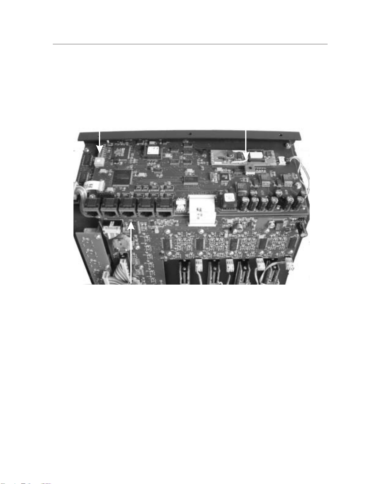
The heart of Logitek Digital Consoles is
the Audio Engine. This is a digital matrix
with equal numbers of input and output
channels ranging from 8x8 to 128x128 in
one engine. This matrix is capable of
mixing, routing, creating mix-minuses
and all other traditional functions of
consoles. The Audio Engine erases the
differences to the user between digital and
analog sources or destinations. The Audio
Engine can accept digital and/or analog
sources and feed digital and/or analog
destinations.
The part of the system in the hands of the user, what looks like an audio console,
is a control surface for the Audio Engine. This can be a ROC 10 or a ROC-5, both
of which look and feel like a traditional console in many respects, the ergonomic
Numix Control Surface or the new compact yet flexible Remora. The Audio
Engine can also be directly controlled by a personal computer using vMix virtual
computer software. Each Audio Engine can accept commands from up to three
consoles or two computers.
4

Unpacking
Carefully unpack the Audio
Engine and control console cartons
looking for any signs of shipping
damage. You may wish to save the
shipping cartons until the
operation of the system is verified
and you are sure there is not hidden
shipping damage. Report any
damage to the shipping carrier
immediately.
The Audio Engine and Control
Surface are boxed separately. Each
box contains a separate packing
list showing the contents. Verify
that the contents of each box
matches the packing list and report
any discrepancies to Logitek in
writing immediately.
Here are several ways to contact Logitek:
U.S. Mail:
Logitek Electronic Systems, Inc.
522 Edgemoor Drive
Houston, Texas 77081
Telephone:
877-231-5870
713-664-4470 (outside U.S. and Canada)
Fax:
713-664-4479
Email:
Website:
www.logitekaudio.com
5Remora Control Surface for Digital Audio Engine

This page is deliberately blank.

Installation
The Remora control surfaces may be surface mounted on a table or cabinet. Connection
of the Control Surface is easy and requires only two cables to the Power Supply Module.
The connecting cable from the Power Supply to the Control Surface is supplied with a
length of 10 feet (3 meters). Other lengths are available as special order options.
Mount the power supply to a wall with the arrow on the front surface pointing up (see
Figure 12). Four screw capturing mounting holes are provided for this purpose. Of the
Power Supply connections the first is a standard computer style AC power cord designed
for IEC power standard. If you require special power cables contact Logitek. Tthe
Remora utilizes an automatic switching power supply so either 110 or 220 volt main
power may be used without modification.
There is no user replaceable fuse but the supply features automatic current limiting.
The second cable is the data cable which connects to the Audio Engine. This cable has a
male DB-9 connector on each end. On the control surface, this connector is attached
adjacent to the power connector. The wiring list for this cable is shown in the Appendix.
Maximum length of the cable is 300 meters or 1000 feet. These cables can be ordered
7Remora Control Surface for Digital Audio Engine
Figure 1 Remora Control Module and Fader Expansion Module

through Logitek in the length
you need. Recommended
wiring for this connection is
Category 5 computer cable.
Wiring to the control surface
from the power supply
connects from a DB-15
connector on one end (power
supply end) to two cables with
RJ-45 connectors on the other
end. These RJ connectors then
connect to modular jacks on
the circuit card behind the
LCD display in the control
surface control module. Jacks
1 and 2 are for the power
supply connectors and jacks 3,
4, and 5 accept similar
connectors from the fader
expansion panels. A selector
switch on this same circuit
board must also be set in the
control module to reflect the
expansion fader modules
attached, if any. The switch
should be set according to the
table in Figure 3.
8
Figure 2 Remora Control Module
Figure 3 Control Module Configuration Switch Settings
Configuration Switch S1
Position 1 4 Fader
2 10 Fader
3 16 Fader
4 22 Fader
All other positions are reserved. Setting to other
switch positions will cause unpredictable
operation or Control Surface failure.

The Remora Console control surface consists of two pieces, a top and a tray. To access
the tray for secure mounting, remove the top by unscrewing the three screws along the
back edge of the top panel and three screws along the front edge. Pull up on this edge and
slide the panel backwards as it comes loose. Reinstall the top by reversing this process.
The contrast for the LCD display is set with a trimmer control R13 on the circuit card
behind the display. This is shown in Figure 4. This is adjusted at the factory for typical
viewing. You can adjust this for the proper viewing angle or lighting conditions in your
installation for normal operation of the Remora. Controls are located behind the displays
for each Remora module and each must be set individually.
9Remora Control Surface for Digital Audio Engine
Figure 4 Control Module Internal Connectors
Display Contrast Control Module Selector Switch
Module Interconnect Jacks (RJ-45)

Operation
The Remora control surfaces are designed to be very familiar in look
and feel to a traditional console yet with the power of the Audio
Engine system easily accessible. Training time is much the same as
for any other console. Many of the differences are seen in the
configuration process and are not obvious to the operator. Following
is a description of the user operated controls.
Faders
Layout of the faders can be seen at left. The stock faders are 100 mm.
Sellmark slide pots. Since the faders are only controls, no audio
passes through them. They only contain control voltage which is used
to change levels in the Audio Engine. The faders operate as step
attenuators with 256 steps from top to bottom. Penny & Giles faders
are available as an option. These faders provide a smoother feel than
the stock units.
Faders may also have “click down” cue switching by setting the Cue
@ Inf function in the configuration software. When the fader is
brought to within .1 inch of the bottom of its travel, the selected input
will be sent to the cue amplifier. This action is independent of the On
and Off buttons so raising the fader out of cue will not change the
current state of those buttons unless Fader Start is activated in
configuration. The Cue @ Inf is enabled or disabled for each input
not for the fader. The “click down” cue action will depend on the input
selected.
Since audio does not pass through the physical faders, they will not become noisy with
wear. Any “scratchiness” of the fader as it moves is averaged out with a special
processing algorithm in the system. If a fader becomes worn, you will notice a slowing
of the fader response to level changes. This is a sign that it is time to change the fader.
10
Figure 5 Remora Fader
Strip Layout

Replacement faders are available complete with ribbon cables and
connectors for quick repairs. You may choose Selmark or optional
Penny & Giles replacement faders. See the Appendix for a list of
Logitek part numbers for use in ordering replacements.
Each fader has illuminated OFF and ON push buttons at the lower end
of the fader. The mix bus selector buttons and the input selector and
display are at the top of the fader.
ON/OFF Buttons are momentary and illuminated with LEDs.
External device controls such as start and stop or auxiliary actions such
as muting or mix-minus can be attached to the functions of the source
ON buttons when configuring the Audio Engine. The external controls
require momentary closures. These attached functions will follow any
change of inputs.
Replacement buttons, lens caps and LEDs are available from Logitek. Part numbers are
listed in the Appendix.
Bus Assign buttons are momentary action and have status indicator
LEDs. The action of the PGM and A1, A2 and A3 buttons is
independent so any or all can be assigned at once. Operation is Push
ON / Push OFF. These buttons correspond to the Program,Aux1,
Aux2, and Aux3 mix buses. Each bus must be assigned to one or
more outputs in AEConfig before is can be used.
Cue is controlled by the momentary push button with indicator
LED. Cue can also be set to turn on with a fader “click-down”. This
is set during configuration. The action of the cue output can be
independent of the fader pot or configured to turn off when the pot is
brought up. When set as independent, the action of the button is
Push ON / Push OFF. For remote operation through GPI control, the
external closure must be sustained for the fader to remain in Cue.
11 Remora Control Surface for Digital Audio Engine
Figure 6 Fader ON
and OFF Buttons
Figure 7 Fader Strip
Operation Buttons

The TB button can allow Talkback to individual
sources as they are selected on a fader. When an
input is selected with a mix-minus configured,
pushing this button will direct the Talkback Mic
audio source to the mix-minus output as long as the
button is pressed. The Talkback Mic and
mix-minus outputs are configured with AEConfig
software during Audio Engine setup.
The Cng (Change) push buttons allow selection of
various options pre-assigned to the fader during
configuration. When one of the buttons is pressed,
the LED lights at the button. This indicates that a
change can now be selected. Use the Select knob at
the upper right corner of the control surface to scroll
through the choices programmed for the button. The
choices are displayed in the LCD panel at the top of
the fader. When the desired choice is found, press
the Yes button near the Select knob to activate the
choice. The choice mode can be cancelled before
pressing the Take button by pressing the Change
button a second time so that the LED goes out, by
pressing a different Change button, or by pressing
the No button.
The IN Change button allows selection of any of the
inputs assigned to the fader during configuration.
This can be as many or as few of the Audio Engine
inputs as you desire. All faders must have at least one
input assigned. Remember that as inputs change, any
attributes attached to that input such as muting or
machine starts will change along with it.
12
Figure 8 Control Module Operation
Controls

The TRM Change button allows the adjustment of
the relative gain level of the input. If the fader
position is at an inconvenient point, adjust the gain up
or down using the Select knob. The adjustment range
is+and-10db.
The MD Change button provides for selection of
fader modes such as Stereo (ST), Mono (MN), Left
Channel only (LL), Right Channel only (RR), or
Phase Reverse(PR). The availability of modes on any
input is set during configuration. The default mode
for stereo and mono inputs is set automatically when
the input is selected.
To adjust the Pan position, use the Select knob after
pressing Pan Change. Press Yes to retain the setting.
Press the No button to cancel any change made. The
Pan setting will show in the center of the bottom line
on the fader LCD display as a vertical bar. The
reference bar shows the center position.
Press the EQ Change button to gain access to the
equalization adjustments of the current input. Choose
the parameter to adjust with the Select knob and press
Yes. Then make the adjustment with the Select knob
followed by Yes to keep or No to cancel the change.
The upper and lower bands provide a frequency and
gain adjustment. These will act as a hish and low
shelf of gain. The middle two bands are parametric
and also include a bandwidth adjustment. Exit the
EQ mode by pressing No until the EQ button goes off
or by pressing another Change button.
The DYN Change button activates adjustment of the
dynamics processing functions. Use the Select knob
to choose the parameter to adjust similar to the EQ
mode. Press Yes to choose, make the adjustment with
the Select knob, and Yes again to keep the change or
No to cancel. The compression and limiting provide
13 Remora Control Surface for Digital Audio Engine
Figure 9 Monitor Controls
Figure 10 Control Module Change Mode
Controls

Threshold, Ratio, Attack, and Release parameters for each. Exit the Dynamics
adjustment mode by pressing No until the DYN button turns off or by pressing another
Change button.
The Cue knob controls the volume of the local cue speaker which has its own amplifier.
Cue audio is returned to the Control Surface from the Audio Engine as digital data on the
Control Surface cable. It is converted to analog at the Control Surface. The relative cue
level is indicated by the indicator bar on the right border of the LCD display.
Monitor Controls
Three Monitor controls are provided on the Remora and are labeled HeadPhones,
Monitor and Studio. The action of each is the same. A level control is present with
each as well as a space on the LCD panel and a Change push button. The right border of
the LCD shows the current source selection of the monitor along with a level indicator on
the top line of each section of the display which shows the relative position of the level
control.
The Phones monitor input may require some special consideration for air monitor with
live microphones. The Audio Engine will introduce a delay of from 1.5 to 2.5
milliseconds from input to output depending on the sample rate used (higher sample rate
14
Figure 11 Remora Control Module LCD Display

gives lower delay). This delay by itself is not objectionable but, when coupled with STL
and air monitor return delays, the total delay may be a problem. Using the flexibility of
the Logitek console, a solution would be to provide a separate post-processor input to
the Audio Engine. This input could be used on the Phones monitor to give the processed
feed to air talent without the extra delay.
To change the source of the monitor control, press the CNG button to the left of thelevel
control. An LED indicator will show that the selection mode is active and the selection
list will appear on the LCD panel. Use the Select knob at the upper right of the Control
Surface to scroll through the available choices which are preset during configuration and
will be listed on the right portion of the LCD. When the desired choice is displayed on
the LCD press the Yes button to activate it. The selection mode can be canceled by
pressing the monitor CNG button again before the Yes button or by pressing another
CNG button or the No button. All of the monitor controls must have at least one device
assignment set during configuration.
15 Remora Control Surface for Digital Audio Engine
Figure 12 Remora Power Supply Connectors

The Source and Destination for the Talkback buttons are set during
configuration. Any input can be sent to either Talkback 1 or
Talkback 2 output. When the associated Talkback button is
pressed, the designated input is sent to the output while the button is
pressed. When the button is released, the connection is broken.
This allows temporary audio connections to be made for such
functions as intercom. The Talkbacks can also have Program IFB
by clicking the Program IFB ON box for the desired Talkback on
the System Page in the AE Configuration Program.
Each fader has its own Timer display above the input description
area. It is count up and the inputs which reset it are set during
configuration.
The meters on the Remora Control Surfaces are multi-function
LED type in a vertical bar which show typical VU levels as well as
peaks. The reference level is adjustable. The meter above the
Monitor controls indicates the level of the Program bus and
follows the outputs assigned as the Program Output bus.
Additional meter sets are located to the right of the LCD display in
each fader section of the Remora. The other set is labeled Monitor
and follows the choice made on the Monitor Control Selector.
The meter LEDs are in a four color arrangement as follows:
Green -35 to -1 db (the normal VU operating range)
Yellow 0 db reference point
Orange +1 to +3 db (the VU warning range)
Red +4 to +16 db (the normal range for peaks)
The zero VU reference level can be set on analog outputs from -20 to +8 db by entering
the desired level as a number in the Normal Signal Level box in the Output Settings
Editor of the configuration software. Separate definitions of outputs can have different
reference levels set during configuration.
16
Figure 13 Remora VU
Meters

The digital output zero VU corresponds to -20 dBFS and cannot be changed.
Other meter scales are available on request such as BBC, European PPM, and
VU only scale. Please contact Logitek for more details.
The 12 user softkeys are programmed and accessed through Command
Builder scripts. These buttons may be programmed to a variety of functions
and are addressed as buses 16 to 27 of Channel 30. This corresponds to
Device 28h, 50h, or 64h for surfaces 1, 2, or 3. The lamps on the buttons are
accessed by the same bus numbers but with devices 27h, 49h, or 63h. See the
Command Builder manual for more details on activating these buttons. The
buttons may also have limited use when programmed through the Command
Library area of AEConfig. See the AEConfig manual for more information.
Initial Power-Up
The Remora will startup with all controls in a neutral position. If the surface is
connected to the Audio Engine then the engine will reset all the switches and
router assignments to the current values for the Control Surface port. The
Control Surfaces reflect the configuration of the Audio Engine port to which
they are attached so that the Control Surfaces may be easily interchanged.
Configuration of the Control Surface port is accomplished in conjunction
with configuration of the Audio Engine. The configuration software runs in
Windows 95/98/NT and requires an available RS232 serial port on the
computer to connect to Port 4 on the AE-C2 card in the Audio Engine. See the
section covering operation of the software for details on Control Surface
setup.
In the event of loss of power at the Control Surface, all switches and indicators
are returned to the same state as before the power loss when the power returns.
17 Remora Control Surface for Digital Audio Engine
Figure 14
Remora Softkeys

The same is true of power loss at the Audio Engine. When power returns the Audio
Engine will return to the same state as before the power failure. When power is restored,
the Audio Engine boot-up time is only two seconds. Loss of power at the Control
Surface will not interrupt audio unless the current audio source ends and the next audio
source fader is OFF.
The Control Surfaces also incorporate a “Watchdog” timer which checks the processor
several times a second. In the event of a software error which locks up the Control
Surface, the lockup will be released by this watchdog in less than one second.
To minimize the chance of program interruptions, use of an uninterruptible power supply
(UPS) is recommended for the Audio Engine. The Remora Control Surfaces consume
approximately 35 watts of power. Select a UPS size to provide the protection time you
need.
18

Appendix
Control Surface Data Cable
Category 5 LAN cable is recommended with a DB9 male at each end. 3 of the 4
twisted pair are used. Ports 1, 2 or 3 are used on the Communications Controller
Card. The rear view of the male connector is shown. Pinout is the same at both
ends. Port 3 has no Cue audio connection so pins 1 and 6 are not connected on
this port and only two pairs are used. All ports operate at 38.4 Kbps, 8 data bits, 1
stop bit and even parity.
Ports 1 and 2
Pin 1 pair 1 Cue + 6 pair 1 Cue -
2 pair 2 TX + 7 pair 2 TX -
3 pair 3 RX + 8 pair 3 RX -
4 no connect 9 no connect
5 enclosure ground

Port 3
Pin 1 no connect 6 no connect
2 pair1TX+ 7 pair1TX -
3 pair 2 RX - 8 pair 2 RX +
4 no connect 9 no connect
5 enclosure ground
20
Table of contents
Other Logitek Recording Equipment manuals
Popular Recording Equipment manuals by other brands

Data Video
Data Video MS-2850G instruction manual

BOSSCO
BOSSCO GT-1 Parameter guide / sound list

Contro l4
Contro l4 MechoShade MechoRF Z1C4 WIIU WH AS installation guide

iCON Pro Audio
iCON Pro Audio V1-M user manual

Entrematic
Entrematic Ditec COM500MHS instructions

Oriental motor
Oriental motor SCX10 Startup manual