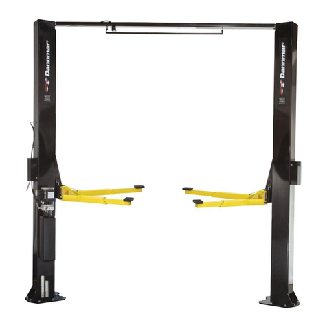
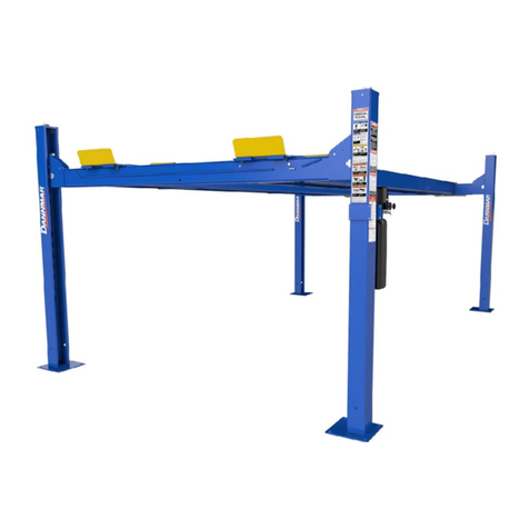
Dannmar D-12 Series User manual

DannmarEquipment
646 FlinnAvenue,SuiteA
Moorpark,
CA 93021
Tel:1-877-432-6627
www.dannmar.com
D-12 SERIES USER MANUAL
IModel: D-12
4-POSTLIFr
12,000POUNDCAPACITY
COMMERCIALGRADE
ALIGNMENTLIFT
12,000POUNDCAPACITY
COMMERCIALGRADE
RevA01-05-2016
PIN17404005
ReferenceANSI/ALIALIOMsafety
requirmentsfor installationandservice
ofautomotivelifts beforeinstallinglift.
Image diaplaya Iha D-12
4-PostUltandpowerunit
configuration.
PLEASEREADTHEENTIRECONTENTSOFnus MANUALPRIORTOINSTALLATIONANDOPERATION.BYPROCEEDINGWITH
LIFTINSTALLATIONANDOPERATONYOUAGREETHATYOUFULLYUNDERSTANDANDCOMPREHENDTHEFULLCONTENTS
OFTHISMANUAL.FORWARDTHISMANUALTOALLOPERATORS.FAILURETOOPERATETHISEQUIPMENTAS DIRECTEDMAY
CAUSEINJURYORDEATH.

12,000 POUND CAPACITY, COMMERCIAL GRADE
FOUR POST AUTO / TRUCK LIFT
ThismanualhasbeenpreparedforyoubyDannmarInc.
Yournewliftisaproductfromyearsofresearchandengineering.
Youarenowaproudownerofthemostadvancedliftingtechnologiesontheplanet.
READ THIS ENTIRE MANUAL BEFORE INSTALLATION & OPERATION BEGINS.
RECORD HERE THE LIFT AND
POWER UNIT INFORMATION WHICH IS
LOCATED ON THE SERIAL NUMBER
DATAPLATES ON THE LIFT AND
ON THE POWER UNIT
~
~
Dannmar Equipment ®
[), •J'• ~' t l ' T , I
Model No. Lifting Capacity Serial No
D-12 / D-12A 12,000lbs.
Dato of Mfq Duty Cycle Volts/Amps
On:90 sec/Off:510sec 230V/18A
www dannmar com
Power Unit Model#
Power Unit Date Of Mfg.
Power Unit Serial # Tel 1-877-432-6627 Fax 1-805-530-1909
G4u Fl11111Ave Stllfe A Moorp,,rk CA <)3021
This information is required when
calling for parts or warranty issues.
PRODUCT WARRANTY
Dannmar 4-Post Lifts are warranted for 3 years on equipment structure, to be free of defects in material and
workmanship . Power Units, hydraulic cylinders , and all other assembly components such as cables, chains, valves,
switches etc. are warranted for one year against defects in material or workmanship under normal use. Dannmar Inc.
shall repair or replace at their option for the warranty period those parts returned to the factory freight prepaid
which prove upon inspection to be defective.
Thewarrantydoesnotextendto...
+ defects caused by ordinary wear, abuse, misuse, shipping damage, improper installation , voltage or lack of
required maintenance ;
+ damages resulting from operator neglect or failure to operate products in accordance with instructions provided
in this manual and/or other accompanying instructions supplied ;
+ normal wear items or service normally required to maintain the product in a safe operating condition ;
+ any component damaged in shipment ;
+ other items not listed but may be considered general wear parts;
+ damage caused by rain, excessive humidity, corrosive environments or other contaminants .
THESE WARRANTIES DO NOT EXTEND TO ANY COSMETIC DEFECT NOT INTERFERING WITH EQUIPMENT
FUNCTIONALITY OR ANY INCIDENTAL , INDIRECT, OR CONSEQUENTIAL LOSS, DAMAGE , OR EXPENSE THAT
MAY RESULT FROM ANY DEFECT, FAILURE, OR MALFUNCTION OF A DANNMAR PRODUCT OR THE
BREACH OR DELAY IN PERFORMANCE OF THE WARRANTY.
LIFT INTENDED FOR INDOOR USE ONLY -OUTDOOR USE PROHIBITED.
2

IMPORTANT NOTICE
Do not attempt to install this lift ifyou have never been
trainedon basicautomotiveliftinstallationproceedures.
Reference ANSI/ALI ALIOM safety requirements for
installation and service of automotive lifts. Never attempt
to lift components without proper lifting tools, such as
a forklift or crane. These instructions must be followed
to ensureproperinstallationandoperationof your lift.
Failure to comply withthese instructions can result in
serious injury and void product warranty. Manufacturer
will assume no liability for loss or damage of any kind,
expressedor impliedresultingfrom improperinstallation
or use of this product.
PLEASE READ ENTIRE MANUAL
PRIOR TO INSTALLATION.
DEFINITIONS OF
HAZARD LEVELS
Identify the hazard levels used in this manual with the
following definitions and signal words:
IA DANGER
DANGER
Watch for this symbol. It Means : Immediate hazards
which will result in severe personal injury or death .
A WARNING
WARNING
Watch for this symbol. It Means : Hazards or unsafe
practices which could result in severe persona l
injury or death.
IACAUTION
CAUTION
Watch for this symbol. It Means : Hazards or unsafe
practices which may result in minor personal injury,
product or property damage.
3
OWNER'S RESPONSIBILITY
To maintain the lift and user safety, the responsibility of the
owne r is to read and follow these instructions :
+ Follow all installation and operation instructions .
+ Make sure installation conforms to all applicable Local,
State, and Federal Codes, Rules, and Regulations;
such as State and Federal OSHA Regulations and
Electrical Codes.
+ Carefully check the lift for correct initial function .
+ Read and follow the safety instructions . Keep them
readily available for machine operators .
+ Make certain all operators are properly trained , know
how to safely and correctly operate the unit, and are
properly supervised.
+ Allow unit operatio n only with all parts in place and
operati ng properly.
+ Carefully inspect the unit on a regular basis and
perform all maintenance as required. Including weekly
lubrication of grease fittings with oil or WD-40.
+ A qualified person should be consulted to address
seismic loads and other local or state requirements.
+ Service and maintain the unit only with authorized or
approved replacemen t parts.
+ Keep all instructions permanently with the unit and all
decals on the unit clean and visible .
BEFORE YOU BEGIN:
Receiving:
The shipment should be thoroughly inspected as soon as it
is received.The signed bill of lading is acknowledgement by
the carrier of receipt in good condition of shipment covered
by your invoice. If any of the goods called for on this bill of
lading are shorted or damaged, do not accept them until the
carrier makes a notation on the freight bill of the shorted or
damaged goods. Do this for your own protection.
NOTIFY THE CARRIER AT ONCE if any hidden loss or
damage is discovered after receipt and request the carrier
to make an inspection. If the carrier will not do so, prepare
a signed statement to the effect that you have notified the
carrier (on a specific date) and that the carrier has failed to
comply with your request.
IT IS DIFFICULTTO COLLECT FOR LOSS OR DAMAGE
AFTER YOU HAVE GIVEN THE CARRIER A CLEAR
RECEIPT. File your claim with the carrier promptly. Support
your claim with copies of the bill of lading, freight bill,
invoice, and photographs , if available. Our willingness to
assist in helping you process your claim does not make
Dan nmar responsible for collection of claims or replace-
ment of lost or damaged materials.

TABLE OF CONTENTS
Contents Page No.
Warranty/ SerialNumberInformation........•........•..... 2
Definationsof HazardLevels..........•........•........•.......
Owner'sResponsibility.••.•........•................................ 3
3
BeforeYou Begin..•.......•........•........•........•........•....... 3
Introduction........•........•........•........•........•........•........• 4
SafetyI WarningInstructions.....•........•........•........•... 4-5
Tools Required..•.......•........•........•.....................•....... 7
Step 1/ SelectingSite ........•........•........•........•........•.. 7
Step2 / FloorRequirements......•........•........•........•... 7
ConcreteSpecifications•••......................................... 7
Assembly/ Descriptionof Parts ......•........•........•....... 8-9
Floorplan/Specifications......................................... 10
PowerUnitLocation....................•.....................•.......
Step3/ ColumnandCrossTubeInstallation•........•..
Step4 / Raisingthe CrossTubes ...•........•........•.......
Step5 / PowersideRunwayInstallation.....•........•.....
11
12
13
14
Step6/ OffsideRunway
Installation......................... 14
Step7/ CableSheaveInstallation............................ 15-16
Step8/ CableInstallation.........................................
16-17
Step9/ PowerUnitInstallation................................. 17
Step10/ RoutingHydraulicHoses........................... 17-18
Step11/ RoutingAirLines....................................... 19
Step12/ Power
UnitHookUp.................................. 20
Step13/ InspectingSlackSafetySprings................ 20
Step14/ LiftStart-Up/FinalAdjustments.................2~21
Step15/ AnchoringtheColumns.............................21-22
Step16/ AttachingApproachRamps/TireStops.... 22
Step17/ LevelingSystem........................................22-23
Step18/ Bleeding..................................................... 23
Step19/ OperationI Maintenance........................... 24-25
SafetyInformation.....................................................26-29
TroubleshootingGuide..............................................3~33
MaintenanceRecords............................................... 34
GeneralDisclaimer.................................................... 36
IA DANGER
Failure to follow danger, warning, and caution
instructions may lead to serious personal injury or death
to operator or bystander or damage to property.
IAWARNING
Please read entire manual prior to installation.
Do not operate this machine until you read and
understand all the dangers, warnings and cautions
in this manual. For additional copies
or further information , contact:
Dannmar Inc.
646 Flinn Ave.
Moorpark, CA 93021
877.432.6627
www.dannmar.com
INSTALLER / OPERATOR
PROTECTIVE EQUIPMENT
Personal protective equipment helps makes installation
and operation safer, however, it does not take the place of
safe operating practices. Always wear durable work
clothing during any installation and/or service activity.
Shop aprons or shop coats may also be worn, however
loose fitting clothing should be avoided. Tight fitting
leather gloves are recommended to protect technician
hands when handling parts. Sturdy leather work shoes
with steel toes and oil resistant soles should be used by all
service personnel to help prevent injury during typical
installation and operation activities.
Eye protection is essential during installation and opera-
tion activities. Safety glasses with side
shields , goggles , or face shields are
acceptable. Back belts provide support dur-
ing lifting activities and are also helpful in
LimitedWarranty....................................................... 38 providing worker protection. Consideration
should also be given to the use of hearing protection if
service activity is performed in an enclosed area, or if
noise levels are high.
THIS SYMBOL POINTS OUT IMPORTANT SAFETY INSTRUCTIONS WHICH IF NOT FOLLOWED
COULD ENDANGER THE PERSONAL SAFETY AND/OR PROPERTY OF YOURSELF AND OTHERS
AND CAN CAUSE PERSONAL INJURY OR DEATH. READ AND FOLLOW ALL INSTRUCTIONS IN
THIS MANUAL BEFORE ATTEMPTING TO OPERATE THIS MACHINE .
4

INTRODUCTION
1. Carefully remove the crating and packing materials .
CAUTION! Be careful when cutting steel banding
materia l as items may become loose and fall causing per-
sonal harm or injury.
2. Check the voltage , phase and proper amperage
requirements for the motor shown on the motor plate.
Wiring should be performed by a certified electrician only.
IMPORTANT SAFETY INSTRUCTIONS
Read these safety instructions entirely!
IMPORTANT NOTICE
Do not attempt to install this lift if you have never been trained on basic automotive lift installation procedures .
Never attempt to lift components without proper lifting tools such as forklift or cranes .
Stay clear of any moving parts that can fall and cause injury.
1. READ AND UNDERSTANDall safety warning proce-
dures before operating lift.
2. KEEP HANDSAND FEETCLEAR.Remove hands and
feet from any moving parts. Keep feet clear of liftwhen
lowering.Avoid pinch points.
3. KEEPWORKAREACLEAN.Clutteredwork areas invite
injuries.
4. Consider work area environment. Do not expose
equipment to rain . DO NOT use in damp or wet locations.
Keep area well lighted.
5. ONLY TRAINEDOPERATORSshould operate this lift.
All non-trained personnel should be kept away from work
area. Never let non-trained personnel come incontactwith, or
operate lift.
6. USE LIFT CORRECTLY. Use liftin the proper manner.
Never use liftingadapters other than what is approved by the
manufacturer.
7. DONOToverride self-closing liftcontrols.
8. REMAINCLEARof liftwhen raising or lowering vehicle.
9. CLEARAREA if vehicle is in danger of falling.
10. ALWAYSENSUREthat the safeties are engaged before
any attempt is made to work on or near vehicle.
11. DRESS PROPERLY. Non-skid steel-toe footwear is
recommended when operating lift.
5
12. GUARDAGAINSTELECTRICSHOCK.This liftmust be
grounded while in use to protect the opera-
tor from electric shock. Never connect the
green power cord wire to a live terminal.
This is for ground only.
13. DANGER! The power unit used on this lift contains high
voltage.Disconnect power atthe receptacle
before performing any electrical repairs.
Secure plug so that it cannot be
accidentally plugged in during service.
14. WARNING!RISKOFEXPLOSION.This equipment has
internal arcing or sparking parts which
should not be exposed to flammable
vapors. This machine should not be located
in a recessed area or below floor level.
15. MAINTAINWITH CARE. Keep lift clean for better and
safer performance. Follow manual for proper lubrication and
maintenance instructions. Keep control handles and/or
buttons dry, clean and free from grease and oil.
16. STAYALERT. Watch what you are doing. Use common
sense. Be aware.
17. CHECKFORDAMAGEDPARTS. Check for alignment
of moving parts, breakage orwear of parts or any condition
that may affect its operation. Do not use lift if any component
is broken or damaged.
18. NEVERremove safety related components from the lift.
Do not use lift if safety related components are damaged
or missing.

6
READ ALL INSTRUCTIONS
IMPORTANT SAFETY INSTRUCTIONS
Read these safety instructions entirely!
(Cont'd)
IMPORTANT NOTICE
19. Care must be taken as burns can occur from touching hot parts.
20. Adequate ventilation should be provided when working on operating internal combustion engines.
21. Keer hair, loose clothing, fingers, and all parts of body away from moving parts.
22. Use only as described in this manual. Use only manufacturer's recommended attachments.
23. ALWAYS WEAR SAFETY GLASSES. Everyday eyeglasses only have impact resistant lenses, they are not safety glasses.
SAVE THESE INSTRUCTIONS
Standard ANSI/ALI ALCTV: 2011, Clause 11.1.6
All worn, damaged, or broken parts must be replaced by parts approved by Dannmar, or with parts
meeting Dannmar's specifications.
Standard ANSI/ALI ALCTV: 2011, Clause 11.1.6
The maximum operating hydraulic pressure developed upon lifting the rated capacity is 3030 psi. The
relief value should not exceed 20% over this value.

TOOLS REQUIRED
• Rotary Hammer Drill or Similar • Large Crescent Wrench
• 3/4" Masonry Bit • Large Pipe Wrench
• Hammer • Crow Bar
• Level - 4 Foot Minimum • Chalk Line
• Open-End Wrench Set: 7/16" - 1-1/8" • Medium Flat Screwdriver
• Socket And Ratchet Set: 7/16" - 1-1/8" • Tape Measure: 25 Foot Minimum
• Hex-Key / Allen Wrench Set • Needle Nose Pliers
IMPORTANT NOTICE
These instructions must be followed to insure proper installation and operation of your lift. Failure to
comply with these instructions can result in serious bodily harm and void product warranty.
Manufacturer will assume no liability for loss or damage of any kind, expressed or implied resulting
from improper installation or use of this product.
PLEASE READ ENTIRE MANUAL PRIOR TO INSTALLATION.
STEP 1
( Selecting Site )
Before installing your new lift, check the following.
1. LIFT LOCATION: Always use architects plans when
available . Check layout dimension against floorplan
requirements making sure that adequate space if
available.
2. OVERHEAD OBSTRUCTIONS:The area where the lift
will be located should be free of overhead obstructions
such as heaters, building supports, electrical lines etc.
3. DEFECTIVE FLOOR: Visually inspect the site where
the lift is to be installed and check for cracked or defective
concrete.
STEP 2
( Floor Requirements )
I .A WARNING
This lift must be installed on a solid level concrete
floor with no more than 3-degrees of slope . Failure
to do so could cause personal injury or death.
A level floor is suggested for proper use and installation
and level lifting. If a floor is of questionable slope,
consider a survey of the site and/or the possibility of pour-
ing a new level concrete slab.
7
I A DANGER
• DO NOT install or use this lift on any asphalt surface
or any surface other than concrete.
• DO NOT install or use this lift on expansion seams or
on cracked or defective concrete.
• DO NOT install or use this lift on a second / elevated
floor without first consulting building architect.
• DO NOT install or use this lift outdoors unless special
consideration has been made to protect the power unit
from inclimate weather conditions.
CONCRETE
SPECIFICATIONS
4"minimumthickness
3000psiminimumcompressivestrength
Maximum
of3-degreeslope
IA DANGER
All models MUST be installed on 3000 PSI concrete only
conforming to the minimum requirements shown above.
New concrete must be adequately cured by at least
28 days minimum.

D-12 FOUR-POST LIFT
DETAILS
~
~e
SCALE1 : 5
/®
~ [la~
DETAILD ci?~
ITEM PART DESCRIPTION
NO. NUMBER
1 120189 DlHYBZS-G1.63H1/ ALOOT1POVVERUNIT
2 17051018 POWERSIDEPOSTASSEMBLY- 0-12 SERIES
3 17051019 POSTASSEMBLY• 0-12 SERIES
4 17052018 POWERSIDERUNWAYASSEMBLY-0-12
5 17052027 OFFSIDERUNWAYWELDMENT- 0-12
6 17053026 4-SHEAVECROSSTUBEASSEMBLY- 0-12 SERIES
7 17053027 2-SHEAVECROSSTUBEASSEMBLY- D-12SERIES
8 17054008 DRIVEUPRAMP.STANDARD.0-12
9 17054010 DRIVEUPRAMP/ 48"LONGANGLED
I 0-12
10 17055013 CABLEASSY012 x 5588mm / 0-12
11 17055018 CABLEASSY012 x 3993mm I 0·12
12 17055019 CABLEASSY012x8901mm / 0-12
13 17055020 CABLEASSY012 x 10490mm/ 0-12
14 17056007 HYDRAULICHOSEASSEMBLY06.4 x 3380mm / 0-12 SERIES
15 17057007 FLEXTUBEASSEMBLY1320mm
16 17057008 PUSHBUTTONAIRASSEMBLY
17 17057060 FLEXTUBEBRACKETASSEMBLY/D·9B.0-12 SERIES
18 17058002 WHEELCHOCK
19 17058003 1/4"POLY-FLOTUBING 17,000mm LG
20 17058326 DRIVERAMPPIN / D·12SERIES
21 17058327 TIRESTOP/ 0-12
QTY. 22 17200025
... 23 17200067
1 24 17200068
1 25 17201010
3 26 17201029
1 27 17201030
1 28 17202008
1 29 17202022
I 30 17202023
2 31 17202039
2 32 17206009
1 33 17206010
1 34 17206013
I 35 17207015
1 . 36 17207033
1 37 17207081
1 38 17207092
1 39 17058062
1 40 172070"0
2 41 17200020
1 '42 17202014
2 43 17201014
2
8
3
3
M14 x90HEX HEADBOLT
M8x 30 HEXHEADBOLT
Ml4 x 40HEXHEADBOLT
MSNYLONLOCKNUT
M22 NYLONLOCKNUT
M14HEXNUT
MSFLATWASHER
Ml4 FLATWASHER
M14SPRINGLOCKWASHER
M22 FLATWASHER
1/4" PUSH-TO-CONNECTTEEFITTING
3/8" MALEPIPE90• ELBOW1/4" PUSH-TO-CONNECTFITTING
9·161NSAEORBx 7·161NJIC.90DEGELBOWWITH0-RING
POWERUNITVIBRATIONDAMPENER
C·WASHERSHIM
ROTORCUP 18mm SS
ZHONGMAO CONCRETEANCHOR BOLT.
0.7S'x S'
ZEROANGLEMTGBRACKET
PUSHBUTTONAIRVAl..1/F.
M3X30SOCl<ETHEADCAPSCREW
M3FLATWASHER
M3NYLONLOCKNUT
4
4
4
4
4
8
4
8
8
4
3
1
1
1
20
4
16
1
1
2
2
2

~
~~
DETAILB
SCALE1: 5
ITEM PART
NO NUMBER
1 120189
2 17051018
3 17051019
4 17052032
5 17052034
6 17053026
7 17053027
8 17054009
9 17055013
10 17055018
11 17055019
12 17055020
13 17056007
1-4 17057007
IS 17057008
16 17057060
17 17058002
18 17058003
19 17058326
20 17058350
D-12A ALIGNMENT LIFT
3
3
DESCRIPTION QTY. 21 17200025 Ml4 x90 HEXHEADBOLT 4
22 17200067 MBx30 HEXHEADBOLT 4
DLHYBZ5-G1.63H1/ ALQOT1POWERUNIT I 23 17200068 M14x40HEXHEADBOLT 4
POWERSIDEPOSTASSEMBLY- D-12SERIES 1 24 17201010 MBNYLONLOCKNUT 4
POSTASSEMBLY·0-12 SERIES 3 25 17201029 M22 NYLONLOCKNUT 4
POWERSIDERUNWAYASSEMBLY- D-12A I 26 17201030 Ml-4 HEXNUT 8
OFFSIDERUNWAYASSEMBLY/ D-12A I 27 17202008 M8 FLATWASHER 4
4-SHEAVECROSSTUBEASSEMBLY- D-12SERIES I 28 17202022 Ml-4 FLATWASHER 8
2-SHEAVECROSSTUBEASSEMBLY- D-12SERIES 1 29 17202023 Ml4SPRING LOCKWASHER 8
DRIVEUPRAMP/ 48"LONG/ D-12A 2 30 17202039 M22 FLATWASHER 4
CABLEASSY012 x 5588mm I D-12 1 31 17206009 1/4"PUSH-TO-CONNECTTEEFITTING 3
CABLEASSY012 x3993mm /0-12 1 32 17206010 3/f! ' MALEPIPE90' ELBOWl/4" PUSH-TO-CONNECTFITTING 1
CABLEASSY012 x890lmm /D -12 I 33 17206013 9-161NSAEORBx7-161NJIC,90DEGELBOWWITH0 -RING 1
CABLEASSY012 x I0490mm / D-12 1 34 17207015 POWERUNITVIBRATIONDAMPENER I
HYDRAULIC HOSEASSEMBLY
06.4 X3380mm / 0-12 SERIES 1 35 17207033 C-WASHERSHIM 20
FLEXTUBEASSEMBLY1320mm 1 36 17207081 ROTORCUP 18mm SS 4
PUSHBUTTONAIRASSEMBLY I 37 17207092 ZHONGMAO CONCRETEANCHOR BOLT, 0.75' xS' 16
FLEXTUBEBRACKETASSEMBLY/0-98, D-12 SERIES 1 38 17058062 ZEROANGLEMTG BRACKET I
WHEELCHOCK 2 39 17207027 PUSH BUTIO NAIRVALVE 1
1/4" POLY-FLOTUBING17.000mm LG 1 40 17200020 M3 X 30SOCKET HEAD CAP SCREW 2
DRIVERAMPPIN/ D-12SERIES 2 41 17202014 M3 FLATWASHER 2
TIRESTOP/ D-12A 2 42 17201014 M3 NYLON LOCKNUT 2
9

FLOORPLAN - SPECIFICATIONS
MODEL
Lifting Capacity:
OverallWidth:
Outside Length:
OverallLength:
Height ofColumns:
Min. RunwayHeight:
Max.Rise:
Max.LiftingHeight:
Width Between Columns:
RunwayWidth:
Width Between Runwa)'$!
LengthofRunways:
Locking Positions:
LockSpacing:
Liftinglim e:
Standard Motor:
Shipping Weight (lbs):
MODEL
Lifting Capacity('):
MaxCapacity/ Front Axle("):
MaxCapacity / Rear Axle(' ):
Overall Width:
Outside Length:
Overall Length:
Height ofColumns:
Min.RunwayHeight:
Max.Rise:
Max.lifting Height:
Width BetweenColumns:
RunwayWidth:
Width Between Runways(' ):
Lengthof Runways:
Min.4-Wheel Alignment (" )
Max.
4-Wheel Alignment(' •)
Max.2-Wheel Alignment (")
Min. Wheelbase
@ RatedCapacity
D-12"'
12,000lbs./ 5443Kg.
130" / 3303mm.
205"I 5205nun.
235" I 5988mm.
89"I 2238mm.
9" / 235mm.
66"/ 1696mm.
75" / 1905mm.
116" / 2946 mm.
20" I 508mm.
43"-51" / 1092 • 1295mm.
191"/4851mm.
13
E,·ery4" / 102mm.
60Seconds
208-230VAC/ 60 Hz. I Ph.
2242
D-12A"'
12,000lbs.I 5443Kg.
6,000lbs. / 2722Kg.
6,000lbs. / 2722Kg.
130"/ 3303mm.
205"I 5207mm.
247"I 6280mm.
89" / 2238mm.
9" I 235 mm.
66" / 1696mm.
75" / 1905
mm.
116"/ 2946 mm.
20"/ 508mm
43"-51" / 1092-1295 nun.
191"/ 4851mm.
98.3"/ 2496mm.
------
IS0.787"I 3829mm.
IS0.787"
I 3829mm.
140"/ 3556mm.
120" / 3048mm.
100"/ 2540mm.
Min. Wheelbase@75%Capacity
Min. Wheelbase
@ 50%Capacity
Min. Wheelbase@25%Capacity
LockingPositions:
LockSpacing:
LiftingTime:
Standard Power Unit ("' )
80" / 2032 mm.
13
Every
4"/ I02 mm.
60 Seconds
208-230VAC/ 60 Hz.l Ph.
• Thi>du D't1'k'>ll m•)· be Iunited Wilhlh• •ddltl<>n of n,llJng)•ck>.
•• M•Yvarydepenwngonwhn!Isiu.
"" Sp..-.:lih'<>h"l!">a,a1i,bl•upon ""lU<>L
D
D
r--==
L
~
L_J
10

11
IMPORTANT
The D-12A Alignment Lift MUST be installed in the configuration shown in Figure 1.
For the D-12 ONLY, the power unit can be located at either "X" locations shown in Figure 1 or 2. It is important to locate
the POWERSIDE runway (with cylinder) on the SAME SIDE as the power unit location. Utility rails on the side of each
runway MUST be installed to the inside. NOTE: In order to change the location of the power unit, the cross tubes and
the powerside runway must be reversed.
Fig 2
Fig 1
POWER UNIT LOCATION
Power Unit X
X Power Unit
Powerside Runway
Powerside Runway

12
STEP3
( Column & Cross Tube Installation )
1. Place a chalk line on the floor according to the floorplan
layout. Pay attention to the power unit location. Locate and
stand the columns at their respective locations. DO NOT
BOLT columns down at this time. Use caution to prevent the
columns from falling over. (See Fig. 1.)
Fig. 1.
2.To estimate the shim requirements, place a target on floor
at each column position and record the readings. Find the
highest of the four locations then find the difference between
each of the remaining columns. This difference is the
estimated amount of shim thickness that will be required at
each column. (See Fig. 2.)
Fig. 2.
Note: The maximum shim thickness recommended by the
factory is no more than 1/2" per column using shims and
anchors provided with the lift.
2. Using a forkliftor crane, raise the cross tubes (making sure
the plasticslide blocks are still in position)and drop down into
the top of the columns. NOTE: The sheave windows should
be positioned inward and adjacent the power unit column.
(See Fig. 3.)
• " SltdeBlocb Musi(.-
, .- - Remainr,Posdlon
,.1:·~ ·- - I r
SheaveWlrdr:HI ,
~
I
r~
'- PowerUnt
MounbogBrad<et
Fig. 3.
Powerum
;r»ilnoBracket
•I
IMPORTANT NOTE I
Lowerthecrosstubesalltheway
downandrestonthe noor.
DDNOTinstall the safetyladders
Insidethe
columnsuntilthe
crosstubesarein position.
3. With the columns standing and the cross tubes in
position , install the safety ladders . Pass the ladders
through the column openings and drop down through the
slide block guide slots on the cross tube until the ladders
come to rest on the base plates. 00 NOT BOLT columns
down at this time. (See Fig. 4-5.)
IMPORTAN T NOTE
Position a nut on the
th~.aded roq as shown
PRIOR to mslalllng
lhe colum n lop cap"S.
This nut will sec ure
the ladder sind prevent it
from ra,:;ang 1,1owards
while the lift 1s tre1r1goperated.
Fig. 4.
Ladde r
Column

Fig 6
13

14
Fig 11
Fig 12
(See Fig 14)
(See Fig 10)
(See Fig 11-12)
Fig 14
(See Fig 13)
Fig 13
(See Fig 14)
(See Page 15)
Fig 10

15
IMPORTANT
It will be necessary to remove
the pins,and spacers
prior to cable installation.
You MUSTre-install these components
back inthe same order as they
Cable
Adj1.:Jsting
A"' Nut
• D
are removed
~
B
Cable Part# Length
Cable A 17055012 3975mm.
Cable B 17055013 5569mm.
Cable C 17055014 8883mm.
Cable D 17055020 10471mm.
Threaded
Cable End
I
~
A •
~
,,,..,"n: ,,,.,,,n·
~~
~
~ i
r\v·
Set Screws
CABLEROUTING IMPORTANTI
InstallCylinder CylinderRetainer
GuideAsShown PlateThisside
CAUTION!
Tighten shaft set
screws securely
after routing cables.
Failure to do so may
result in injury
or damage to lift.

16
Fig 15
Fig 16
Fig 17
Fig 18
(See Fig 15)
(See Fig 16)
(See Fig 17)
(See Fig 18-19)
36
82

17
Fig 19
Fig 20
Fig 21
Fig 22
Fig 23
Fig 24
(See Fig 20-21)
(See Fig 23-24)
AW32 hydraulic oil or Dexron III or VI automatic
transmission fluid. (See Fig 22)
Mount the power
unit to the
mounting bracket
using the hex bolts
and nylon nuts. Fill
reservoir with
AW32 HYDRAULIC
OIL or DEXRON III
or VI ATF

18
Fig 25
Fig 26
Fig 27
Fig 28
Fig 29
Fig 30
(See Fig 25)
(See Fig 27)
(See Fig 28)
(See Fig 30)
(See Fig 29)
(See Fig 26)

STEP 11
( Routing Air Lines )
Route the air line as shown below making sure to position the push button air valve with the INLET facing towards the
AIR SOURCE and the OUTLET facing the direction of the LIFT.
A filter/regulator/lubricator must be installed on air supply at lift. Failure to do so will void the warranty . Cut the
provided 1/4" air line tubing with a sharp blade to lengths as required. Tubing must be cut square with no burrs.
Note: To assemble air line tubing into fitting, use firm, manual pressure to push tubing into the fitting until it bottoms out.
To remove air line tubing from the fitting, hold push sleeve in (against fitting) and, at the same time, pull out on tubing.
Pay careful attention to keep air line clear of any pinch points. Improper assembly may result in safety lock failure.
AIR PRESSURE SHOULD BE REGULATED TO 65 PSI MAX. (See Fig31)
An air supply (30 PSI Min / 3 CFM Min.) will be required for the safety-lock mechanisms .
Fig31
/
Push-Button
Air Valve Tube
Route Airline
Through Pipes
Underneath Runway
Airline
~
tJllll'PushFitting
"Tee" Fitting
Male Branch
"Tee" Fitting
Push Button
Air Valve
Mounting
Bracket
Air Cylinder
Air Cylinder
FeedAirline Through Tubing On Outside Of Cross Tubes
19

20
Make sure the power unit reservoir is full with 12qts of
AW32 hydraulic oil or Dexron III or VI automatic
transmission fluid.
Fig 32
(See Fig 32)
Filler Cap
FILL WITH AW32
HYDRAULIC OIL
OR DEXRON III
OR VI ATF
This manual suits for next models
1
Table of contents
Other Dannmar Lifting System manuals
Popular Lifting System manuals by other brands

MULTILIFT
MULTILIFT Hooklift XR S Series installation instructions

Challenger Lifts
Challenger Lifts CL20 Installation, operation & maintenance manual

Nexus 21
Nexus 21 L-75ix installation manual

Vestil
Vestil VWS-770-AA manual

Blue Giant
Blue Giant BLUE GENIUS TL85 Series Installation & owner's manual

Basta Boatlifts
Basta Boatlifts Over-Center 4.5k37 manual