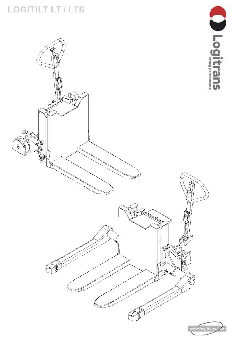
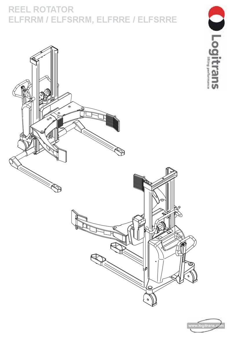
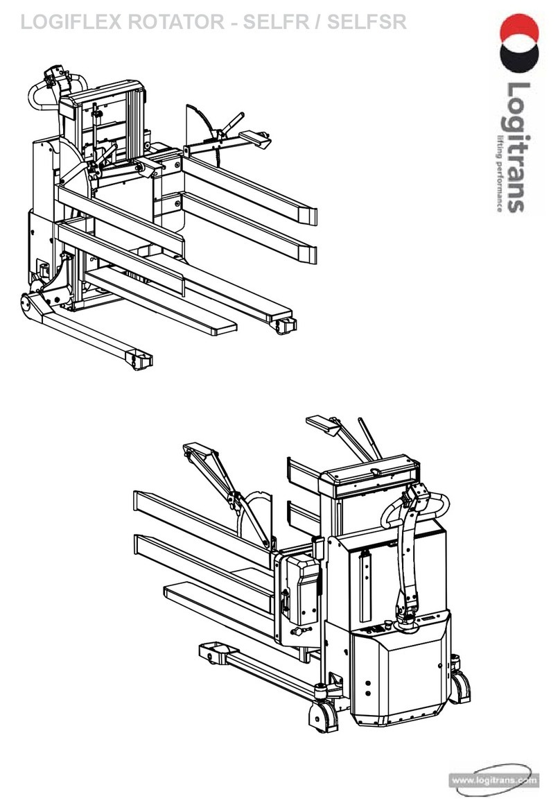
logitrans ELFRRE User manual

REEL ROTATOR
ELFRRE / ELFSRRE, ELFRRM / ELFSRRM

B148
EU DECLARATION CONFORMANCE
Manufacturer: Logitrans A/S
Address:Hillerupvej 35
6760 Ribe
Danmark
hereby declares that:
machine: Product group: Reel Rotator
Type: ELFRRE1001/ELFSRRE1001
ELFRRM1001/ELFSRRM1001
Production year/
Serial no:
a) has been manufactured in conformance with the stipulations of the:
• Directive no. 2006/42/EC
• Directive no. 2014/30/EC
• Directive no. 2014/35/EC
b) has been manufactured in conformance with the stipulations of the standard:
• EN ISO 3691-5
Responsible for the technical dossier:
Name: Gitte Kirkegaard
Address: Hillerupvej 35, DK-6760 Ribe
Signature:
Gitte Kirkegaard, CEO, Logitrans A/S Ribe, 20.03.2020.
D179-4

3
Contents
1.0 Before the first lift... ............................................................................................. 4
2.0 Functions and identifications.......................................................................... 5
3.0 How to operate Reel Rotator ........................................................................... 6
3.1 Handling of reels.................................................................................................................. 6
3.2 Use of the Reel Rotator....................................................................................................... 6
3.2.1 ELFRRE, ELFSRRE......................................................................................................... 6
3.2.2 ELFRRM, ELFSRRM - Manual rotation............................................................................ 7
3.3 Remote control MR-1 / Lifting-Lowering-Rotation-Clamping (ELFRRE,ELFSRRE)............ 8
3.4 Remote control MR-1 / Lifting-Lowering-Clamping(ELFRRM,ELFSRRM) .......................... 8
3.5 Remote control / Lift and lower / Rotation ........................................................................... 9
3.6 Clamping of reels............................................................................................................... 10
3.7 User-Interface LUI-1 Reel Rotator..................................................................................... 12
3.8 Setting up User-Interface LUI-1 Reel Rotator.................................................................... 12
3.8.1 Home display.................................................................................................................. 12
3.8.2 Display for Setup ............................................................................................................ 13
3.8.3 Setting of rotation speed................................................................................................. 13
3.8.4 Setting of stop position ................................................................................................... 14
3.8.5 Deleting stop positions ................................................................................................... 14
4.0 Optimum safety ..................................................................................................... 15
4.1 Safety regulations.............................................................................................................. 15
4.2 Rotation range................................................................................................................... 16
4.3 Driving loaded.................................................................................................................... 16
4.4 Rotation with load.............................................................................................................. 17
4.5 Emergency stop................................................................................................................. 17
5.0 There must be a current supply... ............................................................... 18
5.1 Fuses - replacement.......................................................................................................... 18
5.2 Wirring connections........................................................................................................... 18
6.0 Long live Reel Rotator........................................................................................ 19
6.1 Lubrication and hydraulic oil.............................................................................................. 19
6.2 Oil change ......................................................................................................................... 19
6.3 The hydraulic pump and the gear motor............................................................................ 20
6.4 Reel carriage adjustment................................................................................................... 20
6.5 Adjustment of lifting chain.................................................................................................. 21
6.6 Adjustment of steering wheel chains ................................................................................. 21
6.7 Adjustment of side play...................................................................................................... 22
6.8 Adjusting the Reel Rotator................................................................................................. 23
6.9 Cleaning ............................................................................................................................ 25
7.0 Fault location key ................................................................................................. 26
8.0 Good service after purchase ......................................................................... 28
8.1 Ordering spare parts.......................................................................................................... 28
8.2 Warranty/Compensation.................................................................................................... 28
8.3 Service and repair ............................................................................................................. 28
8.4 Warranty ............................................................................................................................ 28
8.5 Liability exemption............................................................................................................. 28

4
• Proper application
• Physical limitations of the product
• Risks with improper use
The Reel Rotator is manufactured in accordance with safety directives.
Among the subjects dealt with in this Instruction Manual are:
Therefore please read this Instruction Manual carefully!
1.0 Before the first lift...

5
10
9
8
7
6
5
4
3
2
1
1. Handle
2. Lift/Lower
3. Emergency stop
4. Brake
5. User-Interface
6. Remote control
7. Reel Carriage
8. Gripping arm
9. Name plate, serial number
10.Instrument board :
• Battery indicator
• Charging plug (internal or
external charger)
• Plug for extra equipment,
12V maximum 15 Amp
To release the brake:
1. Pull
2. Push
Released position
Braked position
2.0 Functions and identifications

6
ELFRRM & ELFRRE
ELFSRRM & ELFSRRE
3.2 Use of the Reel Rotator
3.2.1 ELFRRE, ELFSRRE
Conditions for rotation: Center of the gripping arms is lifted at least:
ELFRRE: 825 mm
ELFSRRE: 750 mm
ELFRRE/ELFSRRE: The load can be rotated 360º with one adjustable stop in
every side.
Note: The rotation stops automatically, when the gripping arms are placed
horizontally/in position 0°. To continue the rotation function from 0°, the rotation
switch has to be released and activated again in the requested rotation direction.
To lower the reel carriage fully, the reel carriage has to be placed in position 0°.
Soft acceleration / deceleration
The Reel Rotator has soft acceleration / deceleration with the following benets:
• The reel rotation stops precisely.
• The gear is protected, because sudden start / stop are minimised.
Handling of reels on closed pallets
- Use the Reel Rotator with straddle legs!
3.1 Handling of reels
3.0 How to operate Reel Rotator

7
Push the handle to the right -
position “Release”
The reel carriage can now be rotated by
the gripping handle.
Note: The reel carriage can be locked for
each 90°.
ATTENTION !
Check that the load is placed in the load center and is properly locked
before rotating.
3.2.2 ELFRRM, ELFSRRM - Manual rotation
Conditions for rotation: Center of the gripping arms is lifted at least:
ELFRRM: 825 mm
ELFSRRM: 750 mm
3.0 How to operate Reel Rotator

8
3.3 Remote control MR-1 / Lifting-Lowering-Rotation-Clamping (ELFRRE,ELFSRRE)
The remote control is used for:
• Lifting/lowering the reel carriage/reel
• Rotating the reel carriage/reel
• Clamping/fastening
• Opening/releasing
3.4 Remote control MR-1 / Lifting-Lowering-Clamping(ELFRRM,ELFSRRM)
The remote control is used for:
• Lifting/lowering the reel carriage/reel
• Clamping/fastening
• Opening/releasing
3.0 How to operate Reel Rotator

9
NOTE!
Check that the load is placed in the load center and is properly locked
before rotating.
NOTE! The lowering height with remote control is set from factory -
400 mm to the middle of the gripping arms.
3.5 Remote control / Lift and lower / Rotation
Lift / Lower
Press cto lift.
Press dto lower.
Rotation (ELFRRE/ELFSRRE)
Press to rotate in the direction of the arrow.
The rotation is set to rotate continuously from
the factory.
The load can be rotated 360°.
3.0 How to operate Reel Rotator

10
Supporting plate
3.6 Clamping of reels
Extra support
For reels from Ø800mm to Ø1270mm it is possible to use three-points clamping.
By adjusting the shown supporting plate, so
that it supports the reel, it can be prevented
that the reel moves between the two plates
that primarily fasten the reel.
The supporting plate can also be set
as stop for a certain reel diameter.
3.0 How to operate Reel Rotator

11
A
B
Clamping
Press “Clamp” until the green lamp(A) is on.
When red lamp lightens (B), the clamping force is not sucient.
Releasing
Press both buttons at the same time to open the gripping arms.
Note: As a safety precaution, the gripping arms can only be opened, when the
lifting system is without pressure.
3.0 How to operate Reel Rotator

12
1.
2.
3.8 Setting up User-Interface LUI-1 Reel Rotator
3.8.1 Home display
When starting the machine/deactivating the emergency stop in
User-Interface LUI-1, home display is shown.
1. Position of the Gripping arms,
- With green arrow - horizontal (0°)
- With red arrow - programmed
angle
2. Settings
3.7 User-Interface LUI-1 Reel Rotator
User-Interface LUI-1 for:
• Setting speed for rotation
• Setting up to three stop position/angles in both rotation directions
3.0 How to operate Reel Rotator

13
1.2.
3.
4.
5.
3.8.3 Setting of rotation speed
At the Setup display, press “SPEED” and the following is shown.
1. Use ➕⁄➖ to adjust the speed.
2. Use ✔/✖ to accept/cancel
the choice and return to Setup
display.
3.8.2 Display for Setup
At home display, press Setup and the following is shown.
1. Speed (SPEED)
2. Angle stop (STOPS)
3. Service (SERVICE)
4. Output data (LOG)
5. Home display (HOME)
3.0 How to operate Reel Rotator

14
At the Stops display, press on the rst stop in the requested direction, and the
following is shown.
1. Use ➕/➖ to choose the size of
the angle or use TEACH to choose
actual position.
2. Use ✔/✖ to accept/cancel choice
and return to Stops display.
3. At the Stops display choose the
next stop position/angle and
repeat the procedure.
3.8.5 Deleting stop positions
At the Stops display, press “CLEAR ALL” to delete all set stop positions/angles.
3.8.4 Setting of stop position
From the factory, the reel carriage is set to rotate continuously. When the reel carriage
have rotated 360°, the machine stops rotating. If you want rotation to continue, it is
necessary to release/press the rotation switch on the remote control again.
It is possible to set up to three stop positions/angles for rotation in both directions.
If the machine is set with one or more stop positions/angles, the machine cannot
rotate further than the last set stop position/angle.
At home display press Setup, and
afterwards STOPS, and the following
is shown.
3.0 How to operate Reel Rotator

15
4.1 Safety regulations
• Never walk under a raised load!
• Never stand between the gripping arms!
• Before lowering the reel carriage, make certain that no foreign
elements can hinder the free lowering of the reel carriage
• The Reel Rotator is designed for use on an even and level oor
• During transport the reel carriage shall be raised as little as
possible
• Transport with raised reel carriage should be made over the
shortest possible distances and at low speed
• Do not exceed the permitted capacity of the product.
• Check that the chains lift equally. They shall be equally tight when the reel
carriage is loaded
• Chains and chain bolts must not be damaged. Chains that have become
permanently stretched (max. 2 % of original length) must be scrapped
ATTENTION
Moving parts
4.0 Optimum safety

16
4.2 Rotation range
Standard version
The load can be rotated, when the turning point of the reel carriage is raised more
than 750 mm (ELFSRRM/ELFSRRE) and more than 825 mm (ELFRRM/ELFRRE).
Below this range, it is only possible to raise/lower the reel carriage in position 0°.
4.3 Driving loaded
The Reel Rotator is designed for use on even and level oor. During transport the
reel carriage shall be raised as little as possible. Transport with raised reel carriage
should be made over the shortest possible distances and at low speed.
4.0 Optimum safety

17
4.4 Rotation with load
NOTE! Rotation is only allowed to take place, if the Reel Rotater is placed on an
equal oor.
When rotating reels, the operator needs a full
overview of the whole working area, so that the
rotation movement can be stopped before the
reel touches the oor, the items or persons in
the working area.
4.5 Emergency stop
The Reel Rotator has an emergency stop. When activating the
emergency stop, the main current supply is switched o.
The movement of the reel carriage stops immediately when
activating the emergency stop.
4.0 Optimum safety

18
5.1 Fuses - replacement
There are ve fuses in the electrical circuit:
• 10 Amp fuse in the control current circuit
• 20 Amp fuse (plug for extra equipment on the instrument board)
• 20 Amp fuse for built-in charger
• 100 Amp fuse in the main supply from battery
• 40 Amp fuse for rotation
Replacement:
The old fuse is to be removed and replaced by a new one of the same size.
Find out why the fuses blow!
5.2 Wirring connections
Many operational disturbances are caused by bad connections in the
elctrical circuit. Make sure that the connections are in order.
Check connections regularly for damage at insulating caps or bad
connections at plugs etc. Verdigris must be removed from cable
plugs. Keep all screw/nut connections tight.
5.0 There must be a current supply...

19
Regular inspection and the replacement of worn or defective parts in good time will
prolong the life of the Reel Rotator. “Prevention is better than repair”, therefore
ensure:
• That the battery is fully charged every time
• Correct usage
• Regular cleaning
• Periodic safety and service inspection
For safety reasons please check the below every 3 month:
• Tighten loose screw and nuts
• Check that there are no cracks, fractures and deformations in the bearing
construction
• Wearing parts, such as brakes, wheels and bearings, are adjusted and
exchanged continuously
6.1 Lubrication and hydraulic oil
Under normal operation conditions the Reel Rotator requires no
lubrication. All ball bearings are sealed and lubricated for life, and
moving parts have self-lubricating bearings or are treated with grease.
The hydraulic system is lled with hydraulic oil of viscosity class
ISO VG 15. An additive is added to the oil. The concentrate reduces friction and
wear and protects against corrosion. Pre-mixed hydraulic oil with additive is
available from the dealer. The oil is suitable for use in the temperature range -10
to +50° C. A thinner oil is recommended for temperatures lower than -10° C (if
necessary, contact your dealer).
6.2 Oil change
Draining the oil:
1. Bring the unloaded reel carriage down to the lowest position.
2. Most of the oil can be drained by loosening the hydraulic hose union and
briey activating the hydraulic pump with the switch.
3. The remaining oil can be drained from the oil tank by removing the tank.
Oil lling:
4. Fill oil through the lling hole on the tank.
5. Oil quantity: ELFRRM 1750 & ELFSRRM 1750 approx 3 liter
ELFRRE 1750 & ELFSRRE 1750 approx 3 liter
6. Ret the lling cap and bleed the system (6.3).
6.0 Long live Reel Rotator

20
6.3 The hydraulic pump and the gear motor
The hydraulic pump has a S3 “periodic intermittent duty” of 10%. This means that
the pump in total is allowed to operate 1 minute for a period of 10 minutes.
Note! If the pump operates more than 10%, the motor will be damaged due to
superheating.
Bleeding the hydraulic system
With a load of 50-100 kg, the reel carriage must be raised and lowered to top and
bottom position 2-3 times.
Gear motor of the Reel Rotator
The gear motor has a ”short time under constant load” of 10 minutes
(S2=10 minutes). This means that the motor is allowed to operate with the
maximum load for 10 minutes. Hereafter it has to be cooled down to normal
temperature.
Note! The motor will be damaged by superheating, if it operates for a longer time
or if it is not cooled down.
6.4 Reel carriage adjustment
Two of the rollers on the reel carriage are mounted on eccentric pins, so that they
can be adjusted. The adjustable rollers are at the top.
1. Loosen screw (pos. 91)
(key width 5 mm).
2. Eccentric pins (pos. 56)
(key width 8 mm) can now be
turned to give the necessary reel
carriage adjustment.
3. Adjustment must be made on both
sides to ensure uniform loading of the
rollers.
6.0 Long live Reel Rotator
This manual suits for next models
3
Table of contents
Other logitrans Lifting System manuals
Popular Lifting System manuals by other brands

AUTOLIFT
AUTOLIFT ONDA OB Series instruction manual

Dhollandia
Dhollandia DH-L Series Maintenance & Repair Manual

Global Lift
Global Lift ROTATIONAL Series owner's manual

Atlas
Atlas PV-10PX Installation & operation manual

Still
Still LiftRunner B frames Original instructions

AJ
AJ 31078 operating instructions

Titan Lifts
Titan Lifts HD2P-9KCL Installation, operation & maintenance manual

Ergotron
Ergotron StyleView SV22 Assembly instructions

morse
morse 400AM-72-124 Operator's manual

StrongHandTool
StrongHandTool BUILDPRO TDSL4830 instruction manual

HENNESSY INDUSTRIES
HENNESSY INDUSTRIES coats 4TV21NSR1 manual

Vestil
Vestil FTTM-2 Instruction manua