Contents
Safety rules 1
Assembly 2
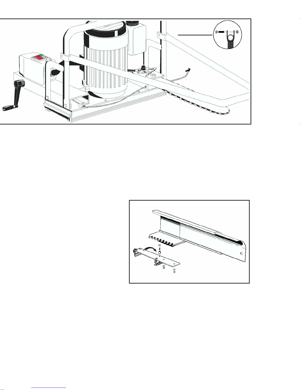
Assembling bar and chain 3
Chain lubrication 4
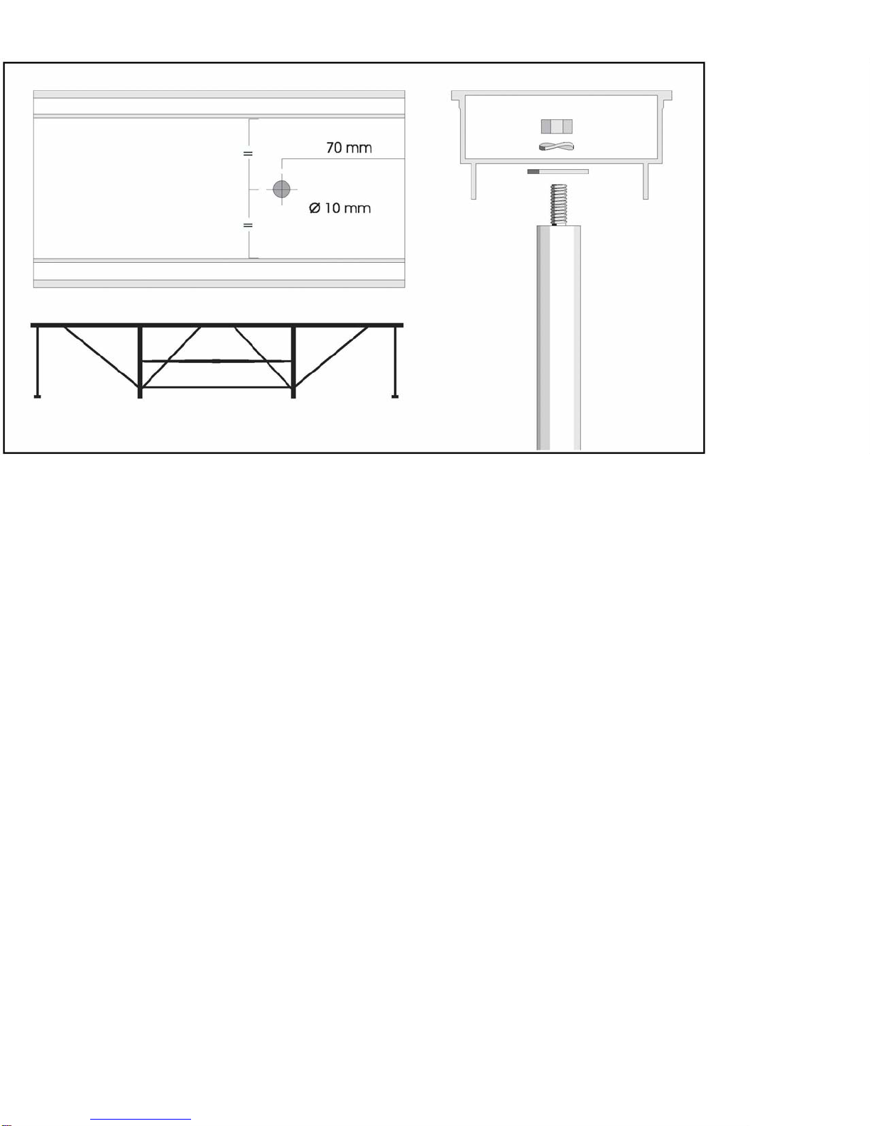
Frame support 5
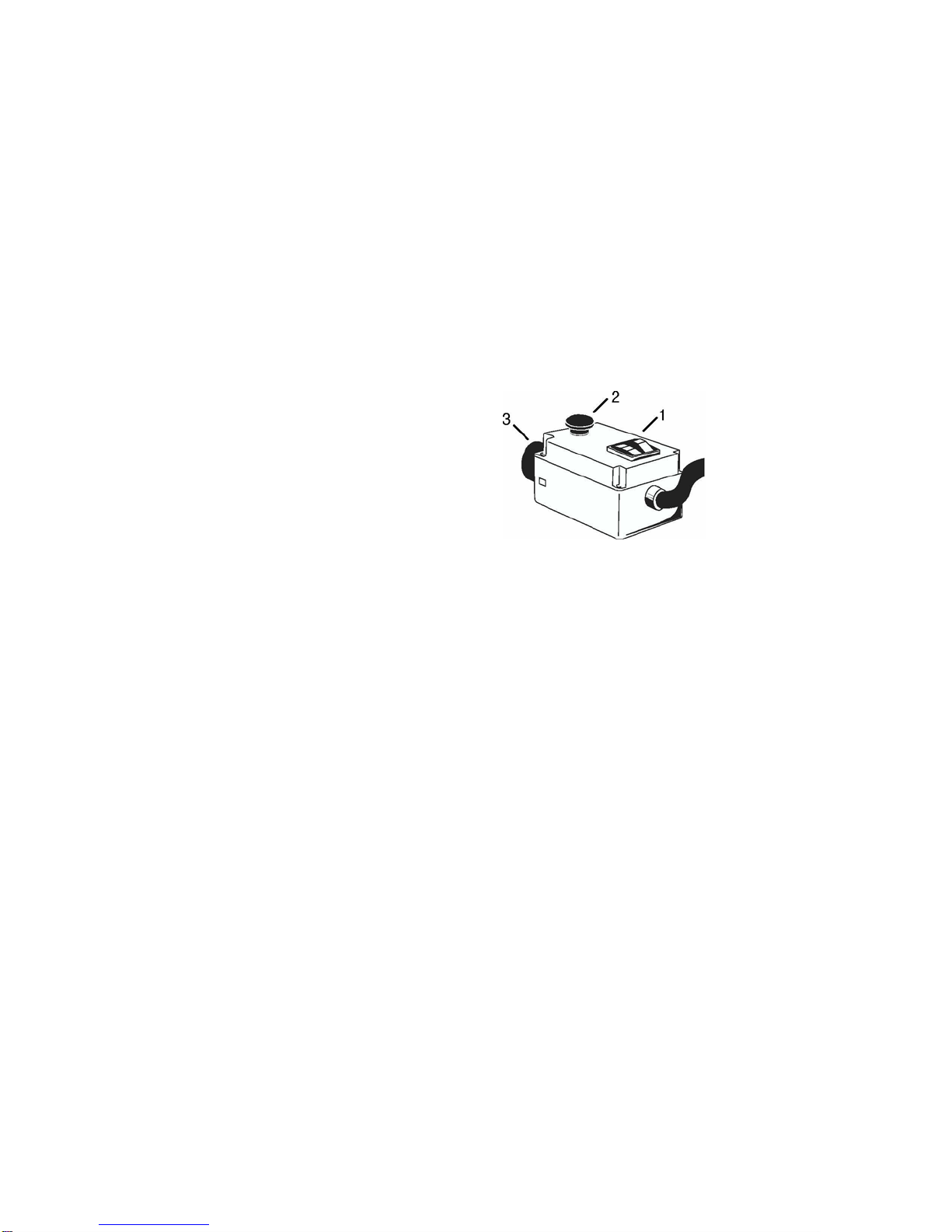
Control light and electric system 6
Cutting equipment 6
Maintenance 7
Belt tension 7
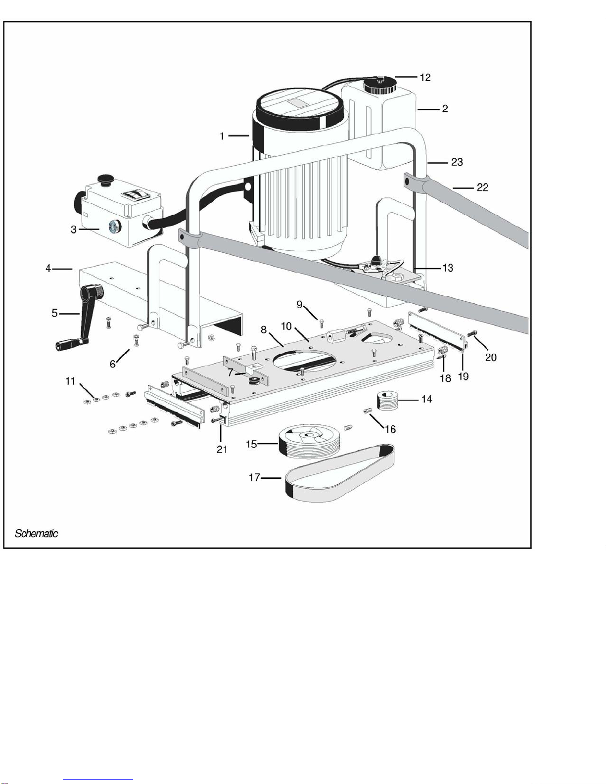
Schematic 8
Parts list 9
Circuit diagram 10
Technical specifications 11
EU manufacturer's declaration 11
Safety rules
•The LOGOSOL E 5000 may only be
used for cross cutting in combination
with the LOGOSOL mini-saw mill.
Incorrect use can cause severe
injury. Always concentrate fully and
work carefully with the sawing unit.
•Attach support legs under the saw
mill guide rail before you attach the
sawing unit. Otherwise the saw mill
may tip over when there is no load
on the log bed.
•Do not wear loose clothing, scarves
and the like which can get caught in
the saw.
•Always check that the saw is solidly
fitted on the guide rail before
plugging in the cable. ln order to
prevent the saw from pitching off the
guide rail when started, ensure that
both plastic strips attach firmly to the
guide rail flange.
•Check that the electric cable runs
free along the entire sawing bed. Do
not step on the cable.
•Turn the saw off after each cut.
•in order to prevent unauthorized
use, never leave the saw
unattended when plugged in.
•Pull the plug out
- before replacing, adjusting and
cleaning the chain, or carrying
out any other maintenance.
- before touching any moving
parts.
- before removing the saw from
the sawmill.
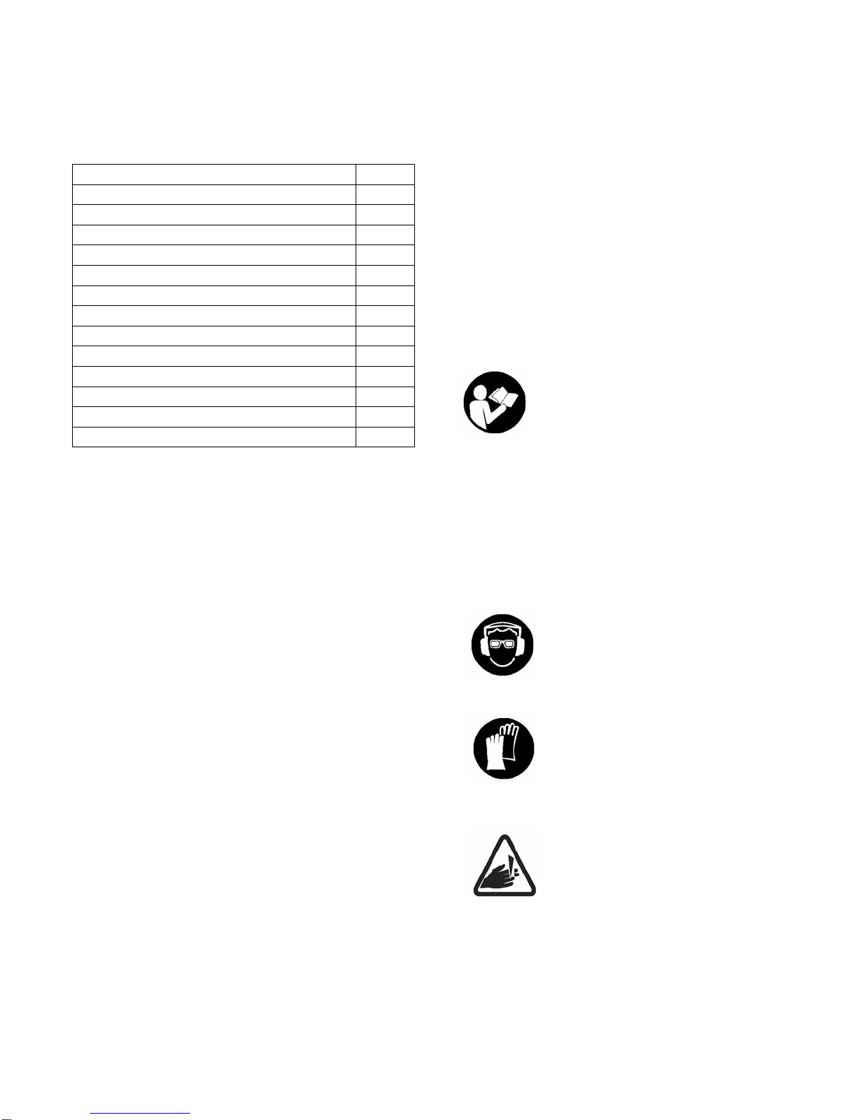
For your own safety, read ail
safety precautions carefully
and do not start the machine
before you have understood
ail of them. Do not allow
persons who have not read
the safety instructions to
operate the machine. You
should also read the
instruction manuals for the
LOGOSOL sawmill.
Use approved hearing
protection and safety glasses.
Even short exposures to high
frequency sounds can
damage your hearing.
Use gloves when you work
with the chain, as there is a
danger of cutting yourself.
Rotating saw chain: do not
insert fingers under the chain
protective cover or past the
sawmill guide rail. Always
stand behind the control arm
while sawing