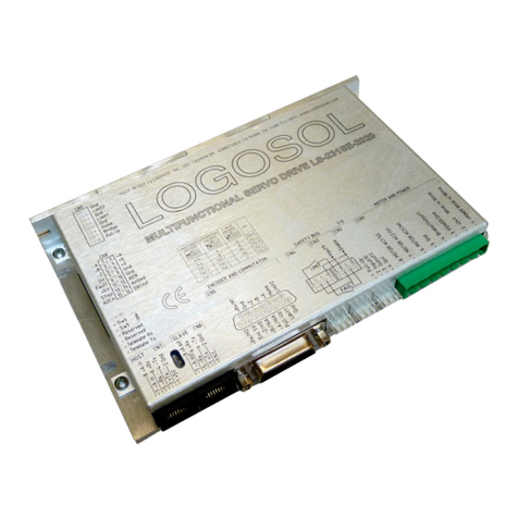
Logosol LS-173AP User manual

Logosol Absolute Positioning Servo Drive LS-173AP
Doc # 712173008 / Rev. 1.06, 05/09/2002
Logosol, Inc. •• 1155 Tasman Drive •• Sunnyvale, CA 94089 Tel: (408) 744-0974 •• www.logosolinc.com
Features
qMotors supported:
-Brushless 60/120°commutated (AC)
-Brush-commutated (DC)
q12A peak, 8A continuous output current
q12 to 90V single power supply
q32-bit position, velocity, acceleration,
16-bit PID filter gain values
qAbsolute positioning analog input
qComprehensive motor output short-circuit
protection:
-Output to output
-Output to ground
-Output to power
qAdjustable motor current limit
qOver/under voltage shutdown
qOverheating protection
qEmergency stop input
qCommunication speed 19.2 -115.2 KBps
qServo rate 2 kHz
qPWM frequency 20 kHz
qCommand rate up to 1000/sec
qEncoder transition rate up to 500kHz.
qSmall footprint (5” x 3.3” x 0.85”)
Description
LS-173AP is a single-
axis absolute positioning
motion controller with integrated servo amplifier
designed for applications using brushl
ess (AC) or
brush-
commutated (DC) motors up to 1 HP. No
jumpers or setup is required to switch between both
types of motors. Trapezoidal brushless motor
commutation is performed automatically if hall
sensors are connected to the unit.
Up to 32 intelligent
servo drives can be controlled
over a multi-drop full duplex RS-
485 network in a
distributed motion control environment. Standard
RJ-
45 connectors and commercially available cables
are used for daisy chaining of the modules.
LS-173AP is equipped with vario
us safety features
such as short circuit protection for the motor and
amplifier, emergency stop input, over and under
voltage shutdown. The maximum motor output
current can be limited by setting of dipswitches.

Logosol Absolute Positioning Servo Drive LS-173AP
Doc # 712173008 / Rev. 1.06, 05/09/2002
Logosol, Inc. •• 1155 Tasman Drive •• Sunnyvale, CA 94089 Tel: (408) 744-0974 •• www.logosolinc.com 2
TECHNICAL SPECIFICATIONS rated at 25oC ambient, POWER (+)=60VDC, Load=250µµH motor
POWER SUPPLY VOLTAGE
12 to 90 V DC, 100V Absolute Maximum
MAX MOTOR OUTPUT CURRENT
Peak
Continuous
12A
8A
MAX MOTOR OUTPUT VOLTAGE Vout= 0.96(POWER (+)) –0.17(Iout)
MIN LOAD INDUCTANCE 200µH
PWM SWITCHING FREQUENCY 19,512 KHz
SERVO RATE 0.512 msec
SERIAL BAUD RATE 19.2 –115.2 Kbps
(faster communication rates are possible at lower servo rates)
OPEN COLLECTOR BRAKE OUTPUT
Max voltage applied to output
Max current load
48V
0.3A
INPUTS
Encoder & Commutation
STP Input
Absolute Positioning analog input
TTL with 1K pull-up to 5V
LOmin=-1V, HImax=48V
0 ÷+5V
ENCODER Quadrature with index
COMMUTATION Hall sensors 60/120o
INDICATORS
Red LED (two intensity levels)
Power ‘ok’ –low intensity
Servo ‘ok’ –high intensity
PROTECTION
Short circuit
Overheating shut off
Motor output to motor output
Motor output to POWER GND
Motor output to POWER (+)
Activated at 80oC
FIRE-SAFETY
Internal fuse
10A Quick blow
POWER DISSIPATION (max) 30W
THERMAL REQUIREMENTS
Storage temperature range
Operating temperature range
–30 to +85oC
0 to 45oC
MECHANICAL
Size
Weight
L=5.00”, H=3.30”, D=0.85”
0.55lb. (250gr.)
MATING CONNECTORS
Power & Motor
Inputs & Outputs
Encoder & Commutator
Communication
Magnum EM2565-06-VL or Phoenix MSTB 2.5/6-ST-5.08
Molex 22-01-3077 housing with 08-50-0114 pins (7 pcs.)
Molex 22-01-3107 housing with 08-50-0114 pins (10 pcs.)
8 pin RJ-45

Logosol Absolute Positioning Servo Drive LS-173AP
Doc # 712173008 / Rev. 1.06, 05/09/2002
Logosol, Inc. •• 1155 Tasman Drive •• Sunnyvale, CA 94089 Tel: (408) 744-0974 •• www.logosolinc.com 3
DIMENSIONAL DRAWING
SERVO DRIVE LAYOUT
ORDERING GUIDE
PART NUMBER MODEL
912173008 LS-Absolute Positioning Servo Drive
230601004 LS-173-CN Mating connector kit

Logosol Absolute Positioning Servo Drive LS-173AP
Doc # 712173008 / Rev. 1.06, 05/09/2002
Logosol, Inc. •• 1155 Tasman Drive •• Sunnyvale, CA 94089 Tel: (408) 744-0974 •• www.logosolinc.com 4
CONNECTORS AND PINOUT
DIP SW –DIP SWITCH
SW SIGNAL DESCRIPTION FACTORY SETTING
1T-out Transmit line terminator OFF
2T-in Receive line terminator OFF
3CL-DCurrent limit switch OFF
4CL-CCurrent limit switch ON
5CL-BCurrent limit switch ON
6CL-ACurrent limit switch ON
7SW1 Reserved (must be set to ON) ON
8SW2 Reserved (must be set to ON) ON
CN1 –POWER AND MOTOR CONNECTOR
PIN SIGNAL DESCRIPTION
1 POWER (+) 12 –90V power supply, positive terminal
2 POWER GND*Power supply ground
3 POWER GND* Power supply ground
4 AC3 or NC
Output to motor
Phase 3 terminal for brushless motor
Not connected for brush motor
5 AC2 or DC (-)
Output to motor
Phase 2 terminal for brushless motor
Negative terminal for brush motor
6 AC1 or DC (+) Output to motor
Phase 1 terminal for brushless motor
Positive terminal for brush motor
*POWER GND and GND are electrically connected. Drive Case is isolated from drive circuitry and can be
grounded externally.

Logosol Absolute Positioning Servo Drive LS-173AP
Doc # 712173008 / Rev. 1.06, 05/09/2002
Logosol, Inc. •• 1155 Tasman Drive •• Sunnyvale, CA 94089 Tel: (408) 744-0974 •• www.logosolinc.com 5
CN2 –I/O CONTROL
PIN SIGNAL DESCRIPTION
1 STP IN Stop input (disable servo amplifier)
2 GND*Signal ground
3 +5V Potentiometer power supply
4 GND* Potentiometer ground
5 ADC Potentiometer (analog) input
6 GND* Signal ground
7 BRAKE OUT Brake output. Open collector output
48V/0.3A.
CN3 –ENCODER AND COMMUTATOR
PIN SIGNAL DESCRIPTION
1 GND* Encoder ground
2 ENCODER Z Encoder index
3 ENCODER A Encoder phase A
4 +5V Encoder power supply
5 ENCODER B Encoder phase B
6 +5V Commutator power supply
7 COMMUTATOR S1 Hall sensor #1
8 COMMUTATOR S2 Hall sensor #2
9 COMMUTATOR S3 Hall sensor #3
10 GND* Commutator ground
CN4 –NETWORK OUT (SLAVE)
PIN SIGNAL DESCRIPTION
1 N.C. Not connected
2 GND* Interface ground
3 +TX (+) Transmit data
4 -TX (-) Transmit data
5 -RX (-) Receive data
6 +RX (+) Receive data
7 -A out (-) Address output
8 +A out (+) Address output
CN5 –NETWORK IN (HOST)
PIN SIGNAL DESCRIPTION
1 +5V RS-232 adapter power supply
2 GND* Interface ground
3 +TX (+) Transmit data
4 -TX (-) Transmit data
5 -RX (-) Receive data
6 +RX (+) Receive data
7 -A in (-) Address input
8 +A in (+) Address input
*POWER GND and GND are electrically connected. Drive Case is isolated from drive circuitry and can be
grounded externally.

Logosol Absolute Positioning Servo Drive LS-173AP
Doc # 712173008 / Rev. 1.06, 05/09/2002
Logosol, Inc. •• 1155 Tasman Drive •• Sunnyvale, CA 94089 Tel: (408) 744-0974 •• www.logosolinc.com 6
SAMPLE APPLICATION using DC (brush) motor

Logosol Absolute Positioning Servo Drive LS-173AP
Doc # 712173008 / Rev. 1.06, 05/09/2002
Logosol, Inc. •• 1155 Tasman Drive •• Sunnyvale, CA 94089 Tel: (408) 744-0974 •• www.logosolinc.com 7
SAMPLE APPLICATION using AC (brushless) motor

Logosol Absolute Positioning Servo Drive LS-173AP
Doc # 712173008 / Rev. 1.06, 05/09/2002
Logosol, Inc. •• 1155 Tasman Drive •• Sunnyvale, CA 94089 Tel: (408) 744-0974 •• www.logosolinc.com 8
LOGOSOL LS-173AP QUICK START GUIDE
Hardware Setup
1. Connect power supply (12 to 90 V DC) to LS-173AP.
2. Connect your motor, encoder and hall sensors.
3. Connect absolute position sensor (potentiometer) to ADC input.
4. Connect RS-232 adapter and RJ-45 network cable between LS-173AP and
your host computer.
Software Installation
1. Installation and using Logosol Distributed Control Network Utility
A. Installation
1. Insert the Logosol Distributed Control Network Utility installation disk into the floppy drive.
2. Select Run from the Windows 95/98/NT Start menu.
3. Type a:\dcnsetup and then click OK (a: represents the drive letter).
4. The installation wizard will guide you through the setup process.

Logosol Absolute Positioning Servo Drive LS-173AP
Doc # 712173008 / Rev. 1.06, 05/09/2002
Logosol, Inc. •• 1155 Tasman Drive •• Sunnyvale, CA 94089 Tel: (408) 744-0974 •• www.logosolinc.com 9
B. Initial Connection to the Host
1. Turn on the power supply.
2. Run the Logosol Distributed Control Network Utility.
3. Choose the proper COM port
4. Click “SERVO” button.
5. Click on “A/D Target” edit box and write your absolute target position.
6. Click “GO” button. The motor should rotate slowly in the proper direction and will stop
when the “A/D Value” becomes equal to “A/D target”. More information about using LDCN
utility is available in LDCN Help.
2. Installation and using Logosol Motion Control Center
A. Installation
1. Insert the Logosol Motion Control Center installation disk into the floppy drive.
2. Select Run from the Windows 95/98/NT Start menu.
3. Type a:\mccsetup and then click OK (a: represents the drive letter).
4. The installation wizard will guide you through the setup process.
B. Initial Connection to the Host
1. Turn on the power supply.
2. Run the Logosol Motion Control Center software.
3. From the Connection menu select Terminal. This will open a terminal window. From the
Target pull-down list select either RS-485-COM1 or RS-485-COM2 corresponding to the
one used to communicate with LS-173AP. Press the Return key to verify that the
connection is established and the command prompt (>) appears on the terminal window.
4. Type INI at the command prompt followed by Return to initialize the controller. It may take
few seconds to complete the process.
5. Type KP A1=20 to set the proportional coefficient, then set the velocity, acceleration and
error limit by the following commands: VEL A1=100, ACC A1=1000 and
MAX A1=8000.
6. Type SER to close the servo loop, then MVP A1=20 to instruct the controller to go to
absolute position 20. Type GO A1 to initiate the motion. The motor should rotate slowly in
the proper direction and will stop when ADC value becomes 20. For more information,
refer to the following MCL*Terminal Interpreter Command Set for executing various motion
commands and parameters settings.
*The information about MCL Terminal Interpreter command set is also available in MCC Help Menu Index
(Advanced Features /Command set for Distributed Servo Drive maintenance).

Logosol Absolute Positioning Servo Drive LS-173AP
Doc # 712173008 / Rev. 1.06, 05/09/2002
Logosol, Inc. •• 1155 Tasman Drive •• Sunnyvale, CA 94089 Tel: (408) 744-0974 •• www.logosolinc.com 10
MCL TERMINAL INTERPRETER COMMAND SET
The following commands are available from the Terminal prompt:
POS –returns and sets current position:
1) "POS"returns the positions of all the axes;
2)"POS A1"returns the position of axis A1;
3) "POS A1=Y"sets the position of axis A1 to the specified value Y.
MAX –returns and sets maximal error (the difference between calculated and real positions):
1) “MAX”returns the maximal errors of all the axes;
2) “MAX A1”returns the maximal error of axis A1;
3) “MAX A1=Y” sets the error limit of axis A1 to the specified value 0<Y<16383.
VEL –returns and sets velocity in velocity mode or goal velocity in trapezoidal mode:
1) “VEL” returns the velocities of all the axes;
2) “VEL A1” returns the velocity of axis A1;
3) “VEL A1=Y”sets the velocity of axis A1 to the specified value Y.
ACC –returns and sets acceleration:
1) “ACC”returns the accelerations of all the axes;
2) “ACC A1” returns the acceleration of axis A1;
3) “ACC A1=Y”sets the acceleration of axis A1 to the specified value Y.
XST –displays status information:
1) “XST”displays status info for all the modules in the network;
2) “XST A1”displays status info for module A1.
Status information for module LS-173AP includes:
1) Address
2) Status byte
3) Auxiliary status byte
4) Encoder position
5) Device ID
6) Version number
7) ADC value.
STA –displays MCL compatible status:
1) “STA”returns MCL compatible status of all the axes;
2) “STA A1”returns MCL compatible status of axis A1.
Note: Status 00000400 -position reached;
00000080 -servo off.
INI –resets the network and assigns individual and group addresses.
STO –stops abruptly:
1) “STO”stops the movement of all the axes;
2) “STO A1”stops the movement of axis A1.
HAL –stops smoothly with specified acceleration:
1) “HAL”stops the movement of all the axes;
2) “HAL A1” stops the movement of axis A1.

Logosol Absolute Positioning Servo Drive LS-173AP
Doc # 712173008 / Rev. 1.06, 05/09/2002
Logosol, Inc. •• 1155 Tasman Drive •• Sunnyvale, CA 94089 Tel: (408) 744-0974 •• www.logosolinc.com 11
KP –returns and sets proportional PID filter parameter:
1) “KP” returns KP parameters for all the axes;
2) “KP A1”returns KP parameter for axis A1;
3) “KP A1=Y”sets KP of axis A1 to the specified value Y.
Note: KP is set to 0 after power-up.
KI –returns and sets integral PID filter parameter:
1) “KI” returns KI parameters for all the axes;
2) “KI A1” returns KI parameter for axis A1;
3) “KI A1=Y”sets KI of axis A1 to the specified value Y.
Note: KI is set to 0 after power-up.
KD –returns and sets deferential PID filter parameter:
1) “KD” returns KD parameters for all the axes;
2) “KD A1”returns KD parameter for axis A1;
3) “KD A1=Y”sets KD of axis A1 to the specified value Y.
Note: KD is set to 0 after power-up.
IL –returns and sets integral limit PID filter parameter:
1) “IL” returns IL parameters for all the axes;
2) “IL A1”returns IL parameter for axis A1;
3) “IL A1=Y”sets IL of axis A1 to the specified value Y.
Note: IL is set to 0 after power-up.
MVP –sets absolute motion position for specified axis in absolute positioning mode:
“MVP A1=Y”.
ABS –sets absolute motion position for specified axis in encoder counts –“ABS A1=Y”.
REL –sets relative motion position for specified axis –“REL A1=Y”.
PWM –returns and sets PWM value in range -255÷255:
1) “PWM”returns the PWM values of all modules.
2) “PWM A1”returns the PWM value of axis A1;
3) “PWM A1=Y”sets PWM of axis A1 to value Y;
FOR –sets forward motion in velocity mode:
1) “FOR A1”sets the motion of axis A1 with the current speed;
2) “FOR A1=Y”sets the motion of axis A1 with the specified speed Y.
REV –sets reverse motion in velocity mode:
1) “REV A1”sets the motion of axis A1 with the current speed;
2) “REV A1=Y”sets the motion of axis A1with the specified speed Y.
GO –starts motion in previously defined mode and parameters:
1) “GO”starts motion of all axes;
2) “GO A1”starts motion of axis A1.
CLI –returns and sets current limit:
Not used.

Logosol Absolute Positioning Servo Drive LS-173AP
Doc # 712173008 / Rev. 1.06, 05/09/2002
Logosol, Inc. •• 1155 Tasman Drive •• Sunnyvale, CA 94089 Tel: (408) 744-0974 •• www.logosolinc.com 12
SER –enables servo:
1) “SER”enables servo of all connected modules;
2) “SER A1”enables servo of module A1.
NOS –disables servo:
1) “NOS”disables servo of all connected modules;
2) “NOS A1”disables servo of module A1.
INX –finds index:
1) “INX A1 F”finds index of axis A1 in forward direction;
2) “INX A1 R”finds index of axis A1 in reverse direction.
Note: if the motor makes more than one revolution to find index, decrease the speed.
FLS –finds limit switch:
Not used.
HEX –hex command mode –sends a low-level command written in hexadecimal format. For
more information about command format refer to “Command Description” section in this
document. Start byte (AA) and checksum byte are generated by the MCL interpreter:
“HEX 01 05” sends Start Motion command (code 0x05) for module with address 1.
BDR –sets baud rate. Possible baud rate values are 9600, 19200, 57600 and 115200:
“BDR 115200” –sets baud rate to 115.2 Kbps.
Note: baud rate is set to 19.2 Kbps after power-up.
HIS –shows the history of the recently used commands, their hexadecimal codes and the
returned status packets.
EXE –executes a text file containing sequence of MCL commands:
“EXE control.dat” –executes the command sequence from “control.dat” file in
current directory.
VER –returns MCL interpreter version.
NET –displays the number and types of all modules in the network and their addresses.
BRL –releases the motor brake to enable manually positioning:
1) “BRL”releases the brakes of all connected modules;
2) “BRL A1”releases the brake of module A1.
DBC –returns and sets amplifier deadband compensation value:
1) “DBC” returns the deadband compensation values of all the axes;
2) “DBC A1” returns the deadband compensation value of axis A1;
3) “DBC A1=Y”sets the deadband compensation value of axis A1 to the value Y.

Logosol Absolute Positioning Servo Drive LS-173AP
Doc # 712173008 / Rev. 1.06, 05/09/2002
Logosol, Inc. •• 1155 Tasman Drive •• Sunnyvale, CA 94089 Tel: (408) 744-0974 •• www.logosolinc.com 13
LS-173AP ARCHITECTURE
Overview
The LS-173AP Absolute Positioning Servo Drive is a highly integrated servo control module
including a motion controller, servo amplifier, serial communication interface, optical encoder
interface, absolute positioning interface and protection circuit (short circuit, under and
overvoltage, overcurrent). The Servo Drive is designed so that up to 32 controllers can be
daisy-chained and connected directly to a single standard serial port (RS-232 adapter may be
necessary).
Functional Diagram

Logosol Absolute Positioning Servo Drive LS-173AP
Doc # 712173008 / Rev. 1.06, 05/09/2002
Logosol, Inc. •• 1155 Tasman Drive •• Sunnyvale, CA 94089 Tel: (408) 744-0974 •• www.logosolinc.com 14
Encoder Input
The encoder interface accepts two square wave inputs, CH_A, CH_B and Index from an
incremental encoder. Ideally, these square waves are 50% duty cycle and exactly +/-90
degrees out of phase. In any case, the time between encoder state transitions should be not
less than 2 µsec. With ideally formed encoder pulses, this would correspond to a 500-line
encoder (2000 counts/rev) rotating at 15,000 RPM.
CW MOTOR DIRECTION
All encoder inputs are with pull-up resistors 1K to +5V.
Encoder and Hall Inputs
Hall Inputs
Hall sensor inputs are placed on the same connector as encoder inputs. All hall sensors are
with pull-up resistors 1K to +5V. 60°/120° hall sensors may be used
Stop input
STP IN is a stop input. If it is high or open the Power Driver will bi disabled (refer to Status Bits
and LED section of this document). STP IN is equipped with pull-up resistors 1K to +5V.
Stop Input
ADC ADC is used as Absolute Positioning analog input. Input voltage is converted to an 8-bit A/D
value (refer to Read Status in Command Description section of this document). In absolute
positioning mode A/D value is compared with Analog Target Value (refer to Absolute
Positioning mode section of this document). If these two values are equal the motor will stop
smooth.

Logosol Absolute Positioning Servo Drive LS-173AP
Doc # 712173008 / Rev. 1.06, 05/09/2002
Logosol, Inc. •• 1155 Tasman Drive •• Sunnyvale, CA 94089 Tel: (408) 744-0974 •• www.logosolinc.com 15
Brake Output
Brake is released (brake output is “on”) when Power_on (bit3 of Status byte) and Pic_ae (bit0
of Stop command data byte) are set to 1.
Brake Output
Brake will be engaged (Brake output is “off”) if:
-STP IN is open;
-Overvoltage;
Overcurrent;
-Motor short;
-Overheat;
-Position error exceeds the position error limit.
Note: For additional information refer to Status bits and LED, Status byte and Auxiliary status
byte and Stop command description, sections of this document. If Power Driver is OK, brake
will be released after Pic_ae 0 to 1 transition.
Dip Switch
Dip switch is used for setting overcurrent limit and terminator control (refer to Overcurrent DIP
Switch Setting of Safety Features section of this document) Two of switches ,T-in and T-out,
are used for connecting terminators to receive and transmit lines. SW-1 and SW-2 are factory
reserved and must be set to ON.
Serial Command Interface
Serial communication with the LS-173AP drives adheres to a full-duplex (4 wire) 8 bit
asynchronous protocol with one start bit, followed by 8 data bits (lsb first), followed by a single
stop bit.
The communication protocol of the LS-173AP also supports a full-duplex multi-drop RS-485
interface that allows multiple LS-173AP Absolute Positioning Servo Drives to be controlled
over a single RS-485 port. In this case, the host sends commands over its RS-485 transmit
line and receives all status data back over the shared RS-485 receive line.
The command protocol is a strict master/slave protocol in which the host master sends a
command packet over the command line to a specific LS-173AP slave. The data are stored in
the buffer of the LS-173AP until the end of the current servo cycle (0.512 msec max.) and
then the command is executed. The servo drive then sends back a status packet. Typically,
the host does not send another command until a status packet has been received to insure
that it does not overwrite any previous command data still in use.
Each command packet consists of following:
Header byte (0xAA)
Address byte -individual or group (0x00 -0xFF)
Command byte
0 -15 data bytes
Checksum byte
The command byte is divided into upper and lower nibbles: the lower nibble is the command
value; the upper nibble is the number of additional data bytes, which will follow the command

Logosol Absolute Positioning Servo Drive LS-173AP
Doc # 712173008 / Rev. 1.06, 05/09/2002
Logosol, Inc. •• 1155 Tasman Drive •• Sunnyvale, CA 94089 Tel: (408) 744-0974 •• www.logosolinc.com 16
byte. The checksum byte is 8 bit sum of the address byte, the command byte and the data
bytes. The number of data bytes depends on the particular command chosen. After a
command is issued, the corresponding controller will send back a status packet consisting of:
Status byte
0-16 optional bytes of status data
Checksum byte
The status byte contains basic status information about the LS-173AP, including a checksum
error flag for the command just received. The optional data bytes may include data such as
the position, velocity, etc. and are programmable by the host. The checksum byte is the 8 bit
sum of the status byte and the additional optional status data bytes. All 16-bit and 32-bit data
is send with the least significant byte first.
Servo Driver Serial Interface
Addressing
Rather than having to hard-wire or switch-select the address of each LS-173AP servo drive,
the host dynamically sets the address of each LS-173AP with the aid of the daisy-chained “A
in” and “A out” lines. This allows additional LS-173AP controllers to be added to an RS-485
network with no hardware changes. On power-up, “A in” of the first LS-173AP is pulled low, its
communication is enabled and the default address is 0x00. When the Set Address command
is issued to give this LS-173AP new unique address, it will lower its “A out” pin. Connecting “A
out” pin to the “A in” pin of the next servo drive in the network will enable its communication at
default address of 0x00. Repeating this process allows a variable number of controllers
present to be given unique addresses. See “Initializing procedure and programming examples
for LS-173AP” later in this document.

Logosol Absolute Positioning Servo Drive LS-173AP
Doc # 712173008 / Rev. 1.06, 05/09/2002
Logosol, Inc. •• 1155 Tasman Drive •• Sunnyvale, CA 94089 Tel: (408) 744-0974 •• www.logosolinc.com 17
Group Addresses
In addition to the individual address, each controller has a secondary group address. Several
LS-173AP controllers may share a common group address. This address is useful for sending
commands, which must be performed simultaneously by a number of drivers (e.g. Start
motion, Set Baud Rate, etc.). When a LS-173AP receives a command sent to its group
address, it will execute the command but not send back a status packet. This prevents data
collisions on the shared response line. When programming group addresses, however, the
host can specify that one member of the group is the “group leader”. The group leader will
send back a status packet just like it would for a command sent to its individual address. The
group address is programmed at the same time as the unique individual address using the Set
Address command.
Multiple Controller Configuration
Communication Rate
The default baud rate after power-up is 19.2 Kbps. Baud rates up to 115.2 Kbps may be used
at maximum servo rate. After communication has been established with all servo drives on a
single network, the baud rate may be changed to a higher value with the Set Baud Rate
command.
Servo Control
LS-173AP uses a “proportional-integral-derivative”, or PID filter. The PWM signal is a square
wave with 51.2 µsec period and varying duty cycle. The PWM value is between 0 and 1023 (0
to 100% duty cycle). Usually, to have better motor control, duty cycle more than 90% is not
recommended. The position, velocity and acceleration are programmed as 32-bit quantities in
units of encoder counts for servo ticks. For example, a velocity of one revolution per second of
a motor with a 500 line encoder (2000 counts/rev) at a tick time of 0.512 msec. would
correspond to a velocity of 1.0240 counts/tick. Velocities and accelerations use the lower 16
bits as a fractional component so the actual programmed velocity would be 1.024 x 216 or
67,109. An acceleration of 4 rev/sec/sec (which would bring us up to the desired speed in ¼
sec) would be 0.0021 counts/tick/tick; with the lower 16 bits the fractional component, this

Logosol Absolute Positioning Servo Drive LS-173AP
Doc # 712173008 / Rev. 1.06, 05/09/2002
Logosol, Inc. •• 1155 Tasman Drive •• Sunnyvale, CA 94089 Tel: (408) 744-0974 •• www.logosolinc.com 18
would be programmed as 0.0021 x 216 or 137. Position is programmed as a straight 32-bit
quantity with no fractional component. Note that if the servo rate divisor is modified, the time
dependent velocity and acceleration parameters will also have to be modified.
PWM Mode Operation
If the position servo is disabled, the motor is operated in a raw PWM output mode and no
trapezoidal or velocity profiling is performed. In this mode, a user specified PWM value is
outputted directly to the amplifier. The maximum PWM value is 255 and corresponding to
100% duty cycle. Command position is continually updated to match the actual position of the
motor and there will be no abrupt jump in the motor’s position when position or velocity modes
are entered. Also while the position servo is disabled, the command velocity is continually
updated to match the actual velocity of motor. Thus, when velocity mode is entered, there will
be no discontinuity in the motor’s velocity. (Trapezoidal profile motions, however, will still force
the motor to begin at zero velocity.).
Absolute positioning mode
External voltage source or potentiometer connected to ADC input is used for absolute
positioning. In this mode Analog Target Value (ATV) is loaded using Load Trajectory
command. To move to an absolute position, load a velocity and acceleration (if not already
loaded), and ATV (Analog Target Value). The ATV will be used as an 8-bit target position and
the controller will start a smooth stop when the A/D value is equal to the loaded ATV. The
direction bit is calculated internally to move in the direction of the command position (ATV).
The Position Servo bit should be set and Velocity Mode bit should be set. The Start Now bit
can be set, or a Start Motion command can be used later. After the motion is started, the Move
Done bit in the Status Byte will remain zero until the actuator has reached the goal position
(A/D = ATV) and the motor has finished decelerating. Issuing a Stop Motor command (with
Motor Off, Stop Smoothly, or Stop Abruptly), or a servo positioning error will terminate the
Absolute Positioning mode until a new command is issued.
Connecting Brushless or Brush Type Motor
LS-173AP is capable of driving brushless commutated (AC) and brush (DC) type motors. No
jumpers or other setting are required. If there are no Hall sensors connected to “ENCODER
AND COMMUTATOR”, LS-173AP drives the motor as brush (DC) type. The positive motor
lead should be connected to “AC1 or DC+” terminal and negative to “AC2 or DC-“ terminal of
“MOTOR AND POWER” connector. If Hall sensors are detected, LS-173AP performs
commutation according to their state.
Often, connecting the brushless motor phases is difficult because of the different terms and
signal names, which different manufactures are using. Here is a simple procedure that may be
used.
Connect the motor commutation sensors to LS-173AP “ENCODER AND COMMUTATOR”
connector according to the next table with most common manufacture signal names.
LS-173AP Encoder & Sensor Connector signal Motor manufacture signal name
S1 RUAS1
S2 SVBS2
S3 TWCS3
Connect the commutator power leads to GND and +5V. Connect the encoder and its power
lines to the same connector. Connect the three motor leads to “AC1 or DC+”, “AC2 or DC-“,
“AC3 or NC” of LS-173AP “MOTOR AND POWER” connector using the same order as for the
commutation sensors. Power on LS-173AP. Initialize the controller. Rotate motor shaft CW

Logosol Absolute Positioning Servo Drive LS-173AP
Doc # 712173008 / Rev. 1.06, 05/09/2002
Logosol, Inc. •• 1155 Tasman Drive •• Sunnyvale, CA 94089 Tel: (408) 744-0974 •• www.logosolinc.com 19
(ClockWise) by hand and check if the motor position is increasing. If motor position is not
changing or it is decreasing, check encoder connection. Set the Drive in PWM mode. Start the
motor with PWM for example 5 (this value might be enough or not depending on motor used)
Set PWM to –5. If the phasing is correct the motor shaft should rotate CW (CCW) smoothly
without any jerks. Otherwise try different motor leads connection. There are only six
combinations and it is recommended to try all of them. Usually only one works fine. If you find
more than one, try to run the motor at higher speed. Set the Drive in velocity mode and start
the motor in CW direction. If the motor runs away, directions of motor and encoder are
opposite. To change the motor direction exchange S1 with S3 and AC1 with AC2. To change
the encoder direction exchange A and B phase wires.
Safety Features
To protect both the user device and the controller, LS-173AP is equipped with various safety
features.
STP IN –Stop Input
For normal operation STP IN signal must be “low”. If it is “high” it will disable the Power Driver
and set status byte bit 3 (Power_on) to zero.
Undervoltage/Overvoltage Protection
LS-173AP is protected against power supply under/overvoltage. In case the power supply is
below 12V hardware reset is generated. More then 91V will disable the Power Driver and set
status byte bit 3 (Power_on) to zero.
Overcurrent Protection
A protection circuit monitors the output current of the motor and limit to a value set by
dipswitch. If the motor is overloaded for less than 200 ms, the output current is limited to the
selected level. Power Driver will be disabled if the motor is overloaded for more then 200 ms.
Use the table to set CL (current limit):
Overcurrent DIP Switch Settings

Logosol Absolute Positioning Servo Drive LS-173AP
Doc # 712173008 / Rev. 1.06, 05/09/2002
Logosol, Inc. •• 1155 Tasman Drive •• Sunnyvale, CA 94089 Tel: (408) 744-0974 •• www.logosolinc.com 20
Status Bits and LED
Bit 3 (Power_on), bit 5 and bit 6 of Status Byte*and bit 0 (Index) of Auxiliary Status byte*are
used for reading input signals and driver diagnostics as shown on tables below.
Power Driver OFF condition (Stop command bit 0 (Pic_ae)=0)
Status byte diagnostic bits
Bit 6
Bit 5
Bit 3
Condition LED intensity
110AOVERVOLTAGE Low
101BSTP IN ACTIVATED Low
011COVERHEAT Low
100DA+B Low
010EA+C Low
001FB+C Low
000GA+B+C Low
111HOK CONDITION Low
Servo Drive diagnostic codes (Stop command bit 0 (Pic_ae)=0
Status byte (hex)
Pos_error =1 Pos_error =0 Fault code description Index
71 61 AOVERVOLTAGE 1
59 49 BSTP IN ACTIVATED 1
39 29 COVERHEAT 1
51 41 DA+B 1
31 21 EA+C 1
19 09 FB+C 1
11 01 GA+B+C 1
79 69 HOK CONDITION 1
Power Driver ON condition (Pic_ae=1)
Status byte
Bit 6
Bit 5
Bit 3
(Power_on) LED intensity
001High
Power Driver Fault condition (Pic_ae=1)
Diagnostic bits
Status byte
Bit 6
Bit 5
Bit 3
(Power_on) Condition LED intensity
100ASTP IN (LATCHED)
OR ENCODER ERROR Low
010BMTOR SHORT** OR
OVERVOLTAGE Low
000COVERCURRENT Low
110DOVERHEAT Low
Diagnostic codes
Status byte Fault code description Index
51h ASTP IN 1
ENCODER ERROR 0
31h BMOTOR SHORT** OR OVERVOLTAGE 1
11h COVERCURRENT 1
71h DOVERHEAT 1
*Refer to Status Byte and Auxiliary Status Byte description in Command Description section of this document.
** MOTOR SHORT –output to output, output to POWER(+) or output to POWER GND
Table of contents
Other Logosol Servo Drive manuals
Popular Servo Drive manuals by other brands

Applied Motion Products
Applied Motion Products SV200 DC Hardware manual

Hiwin
Hiwin E1 Series Operation Procedure

Panasonic
Panasonic MINAS-A5BL Series manual

Acoms
Acoms AS17 Technical note

SSD Parvex
SSD Parvex DIGIVEX Little Drive Servoamplifier User and commissioning manual

Siemens
Siemens SINAMICS S120 Equipment manual