LOMBARDINI MARINE KOHLER OMNILINK User manual

OMNILINK CONTROL PANEL
OWNER MANUAL
USO E MANUTENZIONE
VERWENDUNG UND WARTUNG
USO Y MANTENIMIENTO
UTILISATION ET ENTRETIEN

TRANSLATED FROM THE ORIGINAL MANUAL IN ITALIAN LANGUAGE
Data reported in this issue can be modied at any time by Lombardini Marine
ISTRUZIONI ORIGINALI
Lombardini Marine si riserva il diritto di modicare in qualunque momento i dati contenuti in questa pubblicazione
ÜBERSETZT VOM ORIGINAL HANDBUCH IN ITALIENISCH
Lombardini Marine behält sich das Recht vor, die in dem vorliegenden Dokument enthaltenen Angaben jederzeit zu ändern
TRADUCIDO POR EL MANUAL ORIGINAL EN IDIOMA ITALIANO
Lombardini Marine se reserva el derecho a modicar en cualquier momento los datos incluidos en este documento
INSTRUCTIONS ORIGINALES TRADUITS DE LA LANGUE ITALIENNE
Lombardini Marine se réserve le droit de modier, à tout moment, les données contenues dans cette publication
Drafting body
Ente compilatore
Zuständige Stelle
Ente que lo rellena
Organisme
compilateur
Code document
Codice documento
Code Dokument
Código documento
Code document
Code
document
Modello n°
Modell Nr.
Modelo n°
Modèle n°
Edition
Edizione
Ausgabe
Edición
Revision
Revisione
Revision
Revisión
Édition
Date
issue
Data
emissione
Datum
Erstellung
Fecha
emisión
Date
émission
Date
Review
Data
revisione
Datum
Revision
Fecha
revisión
Date
révision
Written by
Redatto
Erstellt
Redactado por
Rédigé
Endorsed
Visto
Geprüft
Controlado por
Vu
DICOM/ATLO ED0053031450 51463 1° 00 07/2016 07/2016

Important / Importante / Wichtig
• Connect to http://iservice.lombardini.it > KDI KOHLER DIESEL section > login as a guest "Enter as a guest" > "TECHNICAL
DOCUMENTATION" > select "KDI 1903 M-MP" or "KDI 2504 M-MP" and download the latest version of this manual onto your device.
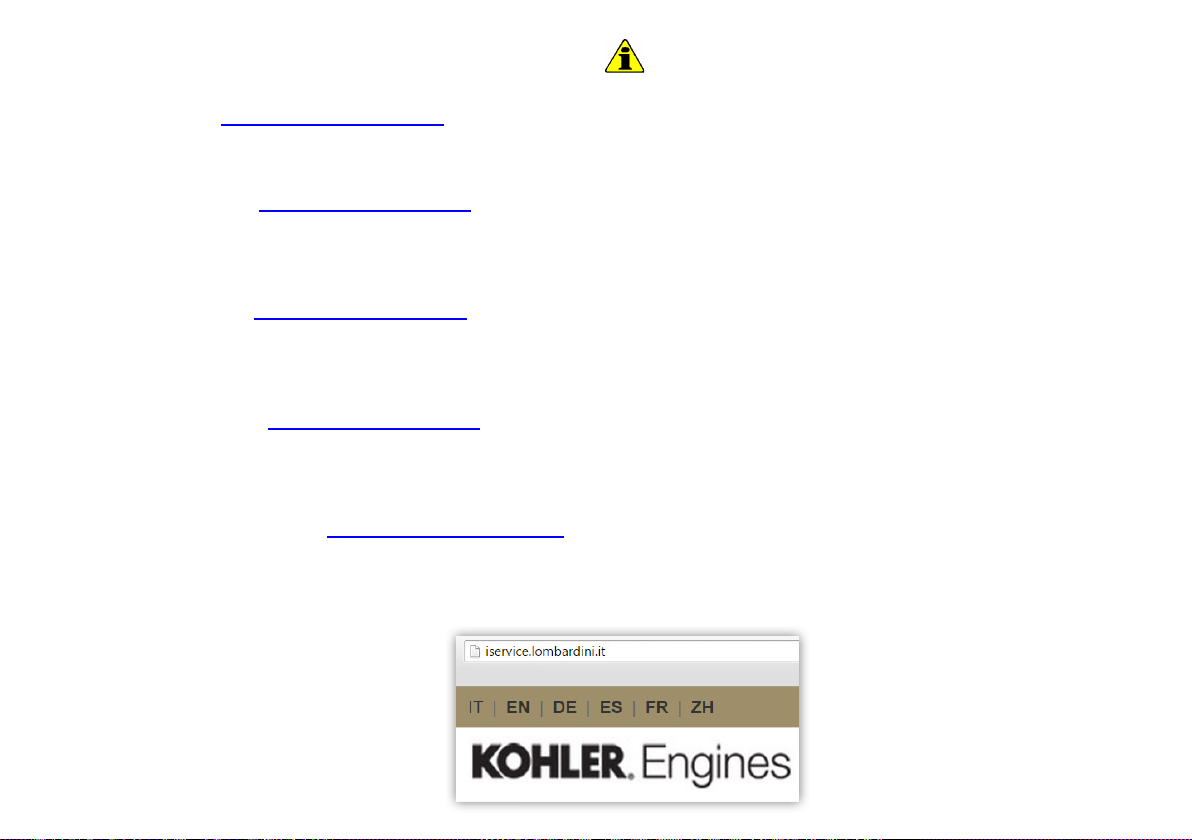
NOTE: you can select the desired language before downloading the manual, as shown in the gure below.
• Collegarsi al sito http://iservice.lombardini.it > sezione KDI KOHLER DIESEL > effettuare l’accesso come ospite “Enter as a guest”
> sezione “DOCUMENTAZIONE TECNICA” > scegliere “KDI 1903 M-MP” o “KDI 2504 M-MP” e scaricare sul proprio dispositivo l’ultima
revisione disponibile di questo manuale.
NOTA: prima di scaricare il manuale è possibile scegliere la lingua desiderata come mostrato nella gura qui di seguito.
• Auf die Webseite http://iservice.lombardini.it > Bereich KDI KOHLER DIESEL > gehen, sich unter “Enter as a guest” als Gast anmelden >
den Bereich “TECHNISCHE DOKUMENTATION” > “KDI 1903 M-MP” oder “KDI 2504 M-MP” wählen und die letzte verfügbare Revision des
vorliegenden Handbuchs herunterladen.
ANMERKUNG: vor dem Herunterladen des Handbuchs kann die gewünschte Sprache gewählt werden, wie in nebenstehender Abbildung erklärt.
• Conéctese al sitio http://iservice.lombardini.it > sección KDI KOHLER DIESEL > efectúe el acceso como invitado “Enter as a guest”
> sección “DOCUMENTACIÓN TÉCNICA” > elija “KDI 1903 M-MP” o “KDI 2504 M-MP” y descargue en su dispositivo la última revisión
disponible de este manual.
NOTA: antes de descargar el manual, es posible elegir el idioma deseado tal como se muestra en la siguiente gura.
• Connectez-vous au site http://iservice.lombardini.it > section KDI KOHLER DIESEL > effectuez l’accès en tant qu’invité
«Enter as a guest» > rubrique « DOCUMENTAZIONE TECNICA »> [Documentation technique] choisissez « KDI 1903 M-MP »
ou « KDI 2504 M-MP » et téléchargez sur votre dispositif la dernière révision disponible de ce manuel.
REMARQUE: avant de télécharger le manuel, il est possible de sélectionner la langue souhaitée, comme montré sur la gure
ci-dessus.

_00
4ED0053031450
OMNILINK CONTROL PANEL
Tab. 1.1
Tab. 1.2
C
E
B
A
D
F
EN
POS. DESCRIPTION
APanel ignition switch with key switch
BEngine on/off push button
CEngine rpm indicator
DEngine data or errors display
EEngine data or errors push button
FMaintenance errors reset push button
POS. DESCRIPTION
Coolant temperature (°C)
Oil pressure (bar)
Battery voltage (V)
1 Components description
Tab. 1.1 shows the control panel components.
Tab. 1.2 shows data that can be consulted on display Dby
pressing push button E.
POS. DESCRIPTION
Total and partial hours of operation (h)
- To reset partial hours, simultaneously
press push buttons Eand Ffor 3seconds
Hours left for maintenance (h)
Backlighting adjustment
- Press push button Efor 3seconds
- Press push button Eto decrease
brightness or Fto increase it

_00 5
ED0053031450
OMNILINK CONTROL PANEL
Tab. 2.1
EN
AMBIENT TEMPERATURE TIME
≤ -20°C 2 minutes
from -20° C to -10°C 1 minutes
from -10° C to -5° C 30 seconds
from -5° C to 5° C 20 seconds
≥ 5° C 15 seconds
2 Starting and turning off
2.1 Starting
1 - Check the level of the engine oil, fuel and coolant and fill if
necessary.
2 - Put the ignition key in the ignition switch.
3 - Tun the key to 1 position.
4 - Press the Start push button for it to start automatically.
Important
• RPM reading delay is normal.
• If engine does not start after two attempts see the engine
owner manual to find the cause.
2.2 After starting
Warning
• Make sure that all the warning lights on the control panel are
off when the engine is running.
• Check for any leakages from the pipes on first start-up
1 - Run at minimum speed for a few minutes (see Tab.2.1).
2.3 Turning off
1 - Do not turn off the engine with a full load or when it is
running at the maximum rotation speed. Leave it running
at idle speed without a load for approximately 1 minute.
2 - Press the Stop push button (the engine turns off) and turn
the key to position 0.

_00
6ED0053031450
OMNILINK CONTROL PANEL
Tab. 3.1
ED
F
EN
3 Error signals on the control panel
Tab. 3.1 shows the errors that can be generated on the control
panel.
Besides visual signals, acoustic errors are also transmitted
from the panel.
Any errors disappear automatically once the anomaly has
been solved.
(*1)- Amaintenance service does not automatically carry out
a reset; it must be reset manually, as follows:
1 - Press the Epush button until the maintenance service page
(Service h) is displayed on the screen D.
2 - Simultaneously press push buttons Eand Ffor 10 secs.
for screen Dto reset the hours until the next maintenance.
POS. DESCRIPTION
Engine oil pressure low
High coolant temperature
Glow Plug or Glow Plug control unit
failure
Disabled alternator (with engine rpm <
850 rpm)
Maintenance service (*1)
Insufcient battery voltage (ashing
display with battery < 9 V)
NOTE: Contact Lombardini Marine authorized workshop for
error signals not shown in Tab. 3.1.

_00 7
ED0053031450
........................................................................................................................................................
........................................................................................................................................................
........................................................................................................................................................
........................................................................................................................................................
........................................................................................................................................................
........................................................................................................................................................
........................................................................................................................................................
........................................................................................................................................................
........................................................................................................................................................
........................................................................................................................................................
........................................................................................................................................................
........................................................................................................................................................
........................................................................................................................................................
........................................................................................................................................................
........................................................................................................................................................
EN
NOTES

_00
8ED0053031450
OMNILINK CONTROL PANEL
POS. DESCRIZIONE
AInterruttore di accensione quadro con chiave
BPulsante accensione e spegnimento motore
CIndicatore di giri del motore
DDisplay di consultazione dati o errori motore
EPulsante consultazione dati o errori motore
FPulsante azzeramento errori di manutenzione
POS. DESCRIZIONE
Temperatura del refrigerante (°C)
Pressione olio (bar)
Voltaggio batteria (V)
1 Descrizione componenti
NellaTab. 1.1 sono indicati icomponentidel quadro dicomando.
Nella Tab. 1.2 sono indicati i dati che è possibile consultare
sul display Dpremendo il pulsante E.
POS. DESCRIZIONE
Ore totali e parziali di funzionamento (h)
- Per l'azzeramento delle ore parziali,
premere contemporaneamente i pulsanti E
ed Fper 3 secondi
Ore rimanenti alla manutenzione (h)
Regolazione della retroilluminazione
- Premere il pulsante Eper 3 secondi
- Premere il pulsante Eper diminuire o Fper
aumentare la luminosità
IT
C
E
B
A
D
F
Tab. 1.1
Tab. 1.2

_00 9
ED0053031450
OMNILINK CONTROL PANEL
TEMPERATURA AMBIENTE TEMPO
≤ -20°C 2 minuti
da -20° C a-10°C 1 minuto
da -10° C a-5° C 30 secondi
da -5° C a5° C 20 secondi
≥ 5° C 15 secondi
2 Avviamento e spegnimento
2.1 Avviamento
1 - Controllare il livello dell'olio motore, del carburante e del
liquido refrigerante e rifornire se necessario.
2 - Inserire la chiave di accensione sul quadro comandi.
3 - Ruotare la chiave in posizione 1.
4 - Premere il pulsante Start, l'avviamento verrà eseguito
automaticamente.
Importante
• Il ritardo della lettura dei giri è normale.
• Nel caso in cui il motore non si avvii dopo due tentativi
consultare il manuale uso e manutenzione del motore, per
individuare la causa.
2.2 Dopo l'avviamento
Avvertenza
• Assicurarsi che tutte le spie di controllo sul quadro di controllo
siano spente dopo l'avviamento.
• Controllare eventuali perdite dai tubi al primo avviamento.
1 - Tenere al minimo per qualche minuto (vedi Tab.2.1).
2.3 Spegnimento
1 - Non spegnere il motore in condizioni di pieno carico o ad
alta velocità di rotazione, lasciarlo funzionare al minimo e
senza carico per circa 1 minuto.
2 - Premere il pulsante Stop (il motore si spegne) e ruotare la
chiavetta in posizione 0.
IT
Tab. 2.1

_00
10 ED0053031450
OMNILINK CONTROL PANEL
3 Segnalazione degli errori sul quadro di comando
Nella Tab. 3.1 sono indicati gli errori che si possono generare
sul quadro di comando.
Oltre al segnale visivo, gli errori sono udibili tramite segnale
acustico proveniente dal quadro.
Gli eventuali errori scompariranno automaticamente non
appena l'anomalia verrà risolta.
(*1) - L'azzeramento automatico non avviene per il tagliando
di manutenzione, l'azzeramento deve essere effettuato
manualmente con la seguente procedura:
1 - Premere il pulsante Efino a visualizzare sul display Dla
pagina del tagliando di manutenzione (Service h).
2 - Premere contemporaneamente il pulsante Eed Fper 10
sec., sul display Dsi ripristinano le ore previste per la
successiva manutenzione.
POS. DESCRIZIONE
Pressione dell'olio motore bassa
Temperatura del refrigerante alta
Candelette o Centralina comando
candelette non funzionanti
Alternatore disattivato
(con giri motore < 850 rpm)
Tagliando di manutenzione (*1)
Voltaggio della batteria insufcente
(display lampeggiante con batteria < 9 V)
NOTA: Per gli errori che non sonodescrittiinTab. 3.1, rivolgersi
alle officine autorizzate Lombardini Marine.
IT
Tab. 3.1

_00 11
ED0053031450
........................................................................................................................................................
........................................................................................................................................................
........................................................................................................................................................
........................................................................................................................................................
........................................................................................................................................................
........................................................................................................................................................
........................................................................................................................................................
........................................................................................................................................................
........................................................................................................................................................
........................................................................................................................................................
........................................................................................................................................................
........................................................................................................................................................
........................................................................................................................................................
........................................................................................................................................................
........................................................................................................................................................
NOTE
IT

_00
12 ED0053031450
OMNILINK CONTROL PANEL
POS. BESCHREIBUNG
ASchalter zur Aktivierung der Steuertafel mit
Schlüssel
BTaste zum Ein- und Ausschalten des Motors
CAnzeige der Motorumdrehungen
DDisplay zur Anzeige der Motordaten und -fehler
ETaste zum Einsehen der Motordaten und -fehler
FTaste zur Rückstellung der Wartungsfehler
POS. BESCHREIBUNG
Kühlmitteltemperatur (°C)
Öldruck (bar)
Batteriespannung (V)
1 Beschreibung der komponenten
In der Tab. 1.1 sind dieKomponentender Steuertafelangeführt.
In der Tab. 1.2 sind die Daten angeführt, die auf dem Display
Ddurch Drücken der Taste Eangezeigt werden können.
POS. BESCHREIBUNG
Teil- und Gesamtzähler der Betriebsstunden (h)
- Zur Rückstellung des Teilzählers der
Betriebsstunden die Tasten Eund F
gleichzeitig 3 Sekunden lang drücken
Verbleibende Stunden bis zur Wartung (h)
Regulierung der Hintergrundbeleuchtung
- Die Taste E3 Sekunden lang drücken
- Die Taste Ezum Erhöhen bzw. die Taste F
zur Reduzierung der Helligkeit drücken
DE
C
E
B
A
D
F
Tab. 1.1
Tab. 1.2

_00 13
ED0053031450
OMNILINK CONTROL PANEL
UMGEBUNGSTEMPERATUR ZEIT
≤ -20°C 2 Minuten
von -20° C bis -10°C 1 Minute
von -10° C bis -5° C 30 Sekunden
von-5° C bis 5° C 20 Sekunden
≥ 5° C 15 Sekunden
2 Anlassen und Abstellen
2.1 Anlassen
1 - Den Stand des Motoröls, des Kraftstoffs und der
Kühlflüssigkeit kontrollieren und wenn nötig nachfüllen.
2 - Den Zündschlüssel in die Steuertafel stecken.
3 - Den Schlüssel in die Position 1 drehen.
4 - Die Start-Taste drücken, das Anlassen erfolgt automatisch.
Wichtig
• Eine Verzögerung beim Ablesen der Umdrehungen ist
normal.
• Sollte der Motor auch bei dem zweiten Versuch nicht
anspringen, anhand von Verwendung und Wartung,
versuchen, die Ursache herauszufinden.
2.2 Nach dem Anlassen
Achtung
• Sicherstellen, dass bei angelassenem Motor keine
Kontrolllampen auf der Steuertafel aufleuchten.
• Beim ersten Anlassen kontrollieren, ob eventuell Leckagen
der Leitungen vorliegen.
1 - Für einige Minuten auf der Mindestdrehzahl halten
(siehe Tab.2.1).
2.3 Abstellen
1 - Den Motor nicht bei voller Belastung oder hoher Drehzahl
abstellen, sondern ihn vor dem Abstellen etwa 1 Minute
lang im Leerlauf und ohne Belastung laufen lassen.
2 - Die Stopp-Taste drücken (der Motor wird abgeschaltet)
und den Zündschlüssel in die Position 0 bringe.
DE
Tab. 2.1

_00
14 ED0053031450
OMNILINK CONTROL PANEL
3 Anzeige der fehler auf der steuertafel
In der Tab. 3.1 sind die Fehler aufgelistet, die auf der Steuertafel
angezeigt werden können.
Neben der visuellen Anzeige werden die Fehler auch durch ein
vonderSteuertafelabgegebenesakustischesSignalgemeldet.
Sobald die Störungen behoben sind, werden die Fehler
automatisch ausgeblendet.
(*1) - Für die Durchführung des Service ist keine automatische
Nullstellung vorgesehen, die Nullstellung muss manuell
erfolgen, dafür folgenden Vorgang befolgen:
1 - Die Taste E drücken, bis am Display Ddie Serviceseite
angezeigt wird (Service h).
2 - Gleichzeitig 10 Sekunden lang die Tasten Eund F
drücken, am Display Dwerden die Stunden bis zum
nächsten vorgesehenen Service rückgestellt.
POS. BESCHREIBUNG
Motoröldruck niedrig
Kühlmitteltemperatur hoch
Glühkerze oder Vorglühsteuergerät
defekt
Drehstromgenerator deaktiviert
(bei Motorumdrehungen < 850 U/min)
Durchführung Service (*1)
Spannung der Batterie unzureichend
(blinkendes Display bei < 9 V)
HINWEIS: Bei Fehlermeldung die nicht in Tab. 3.1 aufgezeigt
sind, kontaktieren Sie eine autorisierte LOMBARDINIMARINE
Werkstatt.
DE
Tab. 3.1

_00 15
ED0053031450
........................................................................................................................................................
........................................................................................................................................................
........................................................................................................................................................
........................................................................................................................................................
........................................................................................................................................................
........................................................................................................................................................
........................................................................................................................................................
........................................................................................................................................................
........................................................................................................................................................
........................................................................................................................................................
........................................................................................................................................................
........................................................................................................................................................
........................................................................................................................................................
........................................................................................................................................................
........................................................................................................................................................
HINWEISE
DE

_00
16 ED0053031450
OMNILINK CONTROL PANEL
POS. DESCRIPCIÓN
A
Interruptor de encendido del cuadro con llave
B
Pulsador de encendido y apagado del motor
C
Indicador de revoluciones del motor
D
Pantalla de consulta de datos o errores del motor
E
Pulsador de consulta de datos o errores del motor
F
Pulsador de puesta a cero de los errores de mantenimiento
POS. DESCRIPCIÓN
Temperatura del refrigerante (°C)
Presión del aceite (bar)
Voltaje de la batería (V)
1 Descripción de los componentes
Enla Tab. 1.1 seindican los componentes del cuadrode mando.
Nella Tab. 1.2 se indican los datos que es posible consultar
en la pantalla Dpresionando el pulsador E.
POS. DESCRIPCIÓN
Horas totales y parciales de funcionamiento (h)
- Para la puesta a cero de las horas parciales,
presione simultáneamente los pulsadores Ey F
durante 3segundos
Horas restantes para el mantenimiento (h)
Regulación de la iluminación posterior
- Presione el pulsador Edurante 3segundos
- Presione el pulsador Epara disminuir o F
para aumentar la luminosidad
ES
C
E
B
A
D
F
Tab. 1.1
Tab. 1.2

_00 17
ED0053031450
OMNILINK CONTROL PANEL
TEMPERATURA AMBIENTE TIEMPO
≤ -20°C 2 minutos
de -20° C a-10°C 1 minuto
de -10° C a-5° C 30 segundos
de -5° C a5° C 20 segundos
≥ 5° C 15 segundos
2
Puesta en marcha y apagado
2.1 Puesta en marcha
1 -
Controle el nivel del aceite del motor, del combustible y del
líquido de refrigeración y reposte si es necesario
.
2 -
ntroduzca la llave de contacto en el cuadro de mandos
.
3 -
Gire la llave a la posición
1.
4 - Presione el pulsador Start; la puesta en marcha será
automática.
Importante
• El retraso en la lectura de las revoluciones es normal.
• En caso de que el motor no se ponga en marcha después de
dos intentos, consulte el manual de uso y mantenimiento, para
descubrir la causa
.
2.2 Después de la puesta en marcha
Advertencia
• Asegúrese de que con el motor en marcha, todos los testigos
luminosos de control del cuadro estén apagados.
• Controle que no haya pérdidas en los tubos en el momento
de la primera puesta en marcha.
1- Mantenga al mínimo durante algunos minutos (Ver Tab.2.1.
2.3 Apagado
1 - No apague el motor en condiciones de plena carga o de
velocidad de rotación alta; déjelo funcionar al mínimo y sin
carga durante 1 minuto.
2 - Presione el pulsador Stop (el motor se apaga) y gire la
llave hasta la posición 0.ES
Tab. 2.1

_00
18 ED0053031450
OMNILINK CONTROL PANEL
3 Comunicación de errores en el cuadro de mando
Nella Tab. 3.1 se indican los errores que se pueden generar
en el cuadro de mando.
Además de la señal visual, los errores pueden oírse mediante
una señal acústica procedente del cuadro.
Los eventuales errores desaparecerán automáticamente
cuando la anomalía se resuelva.
(*1) - La puesta a cero automática no tiene lugar con el
procedimientodemantenimiento,debe realizarsemanualmente
con el siguiente procedimiento:
1- Presione el pulsador Ehasta ver en la pantalla Dla página
del documento de mantenimiento (Service h).
2- Presione simultáneamente los pulsadores Ey Fdurante 10
s, en la pantalla Dse restablecen las horas previstas para
el siguiente mantenimiento.
POS. DESCRIPCIÓN
Presión del aceite del motor baja
Temperatura refrigerante alta
Bujías o Centralita de control bujías
no funcionan
Alternador desactivado (con
revoluciones del motor < 850 rpm)
Documento de mantenimiento (*1)
Voltaje de la batería insuciente
(pantalla intermitente con batería < 9 V)
NOTA: Para los errores que no están descritos en la Tab. 3.1,
diríjase a las estaciones de servicio autorizadas Lombardini
Marine.
ES
Tab. 3.1

_00 19
ED0053031450
........................................................................................................................................................
........................................................................................................................................................
........................................................................................................................................................
........................................................................................................................................................
........................................................................................................................................................
........................................................................................................................................................
........................................................................................................................................................
........................................................................................................................................................
........................................................................................................................................................
........................................................................................................................................................
........................................................................................................................................................
........................................................................................................................................................
........................................................................................................................................................
........................................................................................................................................................
........................................................................................................................................................
NOTAS
ES

_00
20 ED0053031450
OMNILINK CONTROL PANEL
POS. DESCRIPTION
AInterrupteur à clé de mise en marche du tableau
BBouton de marche et d’arrêt du moteur
CIndicateur des tours du moteur
DÉcran pour consultation des données ou des
erreurs du moteur
EBouton pour consultation des données ou des
erreurs du moteur
FBouton de réinitialisation des erreurs d’entretien
POS. DESCRIPTION
Température du réfrigérant (°C)
Pression de l’huile (bar)
Tension de la batterie (V)
1 Description des composants
Dans le Tab. 1.1 sont indiqués les composants du tableau de
commande.
Dans le Tab 1.2 sont indiquées les données qu’il est possible
de consulter à l’écran Den appuyant sur le bouton E.
POS. DESCRIPTION
Heures totales ou partielles de
fonctionnement (h)
- Pour la remise à zéro des heures
partielles, appuyer simultanément sur les
boutons Eet F, pendant 3 secondes
Heures restantes jusqu’à l’entretien (h)
Réglage du rétroéclairage
- Appuyer sur le bouton Ependant 3 secondes
- Appuyer sur le bouton Epour diminuer ou
Fpour augmenter la luminosité
FR
C
E
B
A
D
F
Tab. 1.1
Tab. 1.2
Table of contents
Languages: