Electro-Air EA-15000 User manual

Electroair Acquisition Corp. IM EA-15000 Page 1 of 10
Revision 01 Prepared by: EAC 02/04/2020
Electroair Acquisition Corp.
5097 Williams Lake Road
Waterford, MI 48329 U.S.A.
Phone: 248-674-3433 Fax: 248-674-4231
Email: sales@electroair.net
EA-15000
Installation Manual
Ignition/Starter Switch Panel
For Two Magnetos

Electroair Acquisition Corp. IM EA-15000 Page 2 of 10
Revision 01 Prepared by: EAC 02/04/2020
Table of Contents
REVISION LOG .............................................................................................................. 2
OVERVIEW OF IGNITION/STARTER SWITCH PANEL INSTALLATION ..................... 3
EA-15000 KIT DESCRIPTION & REQUIREMENTS ....................................................... 4
EA-15000 KIT CONTENTS ............................................................................................. 4
RECEIVING AND ACCEPTANCE CHECKING OF EA-15000 KIT ................................ 4
PRECAUTIONARY STATEMENTS: ............................................................................... 5
INSTALLATION OF EA-15000: ...................................................................................... 6
GLOSSARY AND ABBREVIATIONS: .......................................................................... 10
Table of Figures
Figure 1: Configuration A Overall Dimensions ............................................................... 6
Figure 2: Configuration B Overall Dimensions………………………………………………6
Figure 3: Configuration A Cutout Dimensions ................................................................ 7
Figure 4: Configuration B Cutout Dimensions ................................................................ 8
Figure 5: Configuration A and B Back Surfaces……………...……………………………..9
Revision Log
Revision Pages
Affected
Date of
Revision
Description of
Revision
Approved
by
Date of FAA
Approval
00 09/15/2017 Initial Release 02/06/2018
01 1,2,4,5,7,8,9 02/04/2020 ECO 1019-0079
Electroair Acquisition Corp. IM EA-15000 Page 3 of 10
Revision 01 Prepared by: EAC 02/04/2020
Overview of Ignition/Starter Switch Panel Installation
Thank you for purchasing an Electroair EA-15000 Ignition/Starter Switch Panel. The
next pages will provide a step-by-step process of installing the Ignition/Starter Switch
Panel on the aircraft. Electroair hopes you will enjoy the experience and that this
manual will provide clear direction and guidance through this process. This manual will
cover the following general installation steps:
1. General overview and recommendations
2. Removal of old ignition components
3. Set-up & installation of p/n: EA-15000 Ignition/Starter Switch Panel
4. Final installation steps
Electroair strongly recommends reading through this entire installation procedure before
installing the Electroair Ignition/Starter Switch Panel to your aircraft. Make sure that any
questions are answered before the actual installation. Also, make sure any extra
components needed, e.g. cable ties, switch terminations, etc., are available. Removal
of old components and installation of new components shall be completed in
compliance with CFR Title 14 Part 43, as applicable, and any Airframe or Engine
Manufacturer Maintenance Procedures, as applicable. Above all else, use good
common sense and professional judgment. An ignition/starter switch panel is an
electrical device. If an ignition/starter switch panel is improperly installed, severe
damage could be caused to the ignition/starter switch panel, aircraft, or installer
including bodily injury or death.
Please contact Electroair with any questions during this installation process. Good luck
and happy flying!!
Electroair

Electroair Acquisition Corp. IM EA-15000 Page 4 of 10
Revision 01 Prepared by: EAC 02/04/2020
EA-15000 Kit Description & Requirements
EA-15000 System Description & Requirements:
1. This kit replaces the rotary key switch on aircraft with an two magnetos.
2. 12V or 24V electrical system capable of 0.75A.
Other items needed:
1. Basic tools and standard aircraft hardware required for mounting EA-15000
Ignition/Starter Switch Panel.
2. Electrical tools for cutting, stripping, and terminating various wiring. Also
recommended is a good selection of cable ties for harness routing and tie-off,
and a selection of shrink tubing for covering exposed electrical connections.
EA-15000 Kit Contents
EA-15000 Kit Contents:
1. ___EA-15000 Panel with Switches
2. ___Baggie with connectors and connecting hardware
3. ___USB Drive Containing System Documents (Installation Manual, STC, ICA)
4. ___Warranty registration**
**USE THIS TO OBTAIN THE STC AUTHORIZATION LETTER**
Receiving and Acceptance Checking of EA-15000 Kit
1. Inspect the packaging for damage before acceptance from the freight carrier. If
damaged, refuse the package.
2. Open the package.
3. Inventory the contents of the package to the content listing of the package.
4. Are all of the materials there? If yes, proceed to step 5. If no, proceed to step 9.
5. Inspect the switches for broken plastic.
6. Inspect the panel for bends
7. Are all materials acceptable?
8. If yes, proceed with installation.
9. If no, contact the factory. Have the serial number of the kit available when
contacting. (factory 248-674-3433 or sales@electroair.net)
If possible, store parts in original packaging when not in use. If not possible, wrap parts
in cushioning material and place in one location. Review above prior to reinstallation.
For latest copies of documentation, refer to www.electroair.net.
Approved Model Listing (AML)
Approved Flight Manual
Supplement (AFMS)
Instructions for Continued
Airworthiness (ICA)
Installation Manual (IM)
Supplemental Type Certificate
(STC)
Trouble Shooting Instructions
(TSI)

Electroair Acquisition Corp. IM EA-15000 Page 5 of 10
Revision 01 Prepared by: EAC 02/04/2020
Precautionary Statements:
ALWAYS STAY OUT OF THE PROPELLER ARC!
CAUTION: Disconnect the battery before starting this procedure.
CAUTION: Prior to any drilling or cutting, verify that there is proper clearance.
CAUTION: Do not cut or alter any structural tubing, aluminum panels, or skin.
CAUTION: Follow these instructions very carefully to insure a correct hook-up of
the Ignition/Starter Switch Panel. Skipping ahead or taking short cuts increases
the risk of an incorrect installation and either a poor performing EIS or the
possibility of damaging equipment. Prior to turning on bus power, verify the
wiring. Please call Electroair with any questions (sales@electroair.net or 248-
674-3433).
CAUTION: Do not secure any radio communication, navigation, transponders or
intercom wiring to any ignition related wires, boxes, or sensors. Doing so will
cause poor to noisy transmission or reception of com and intercom and/or poor
or no navigation function. Keep at least 3 inches between these wires.
CAUTION: If using a non-impulse coupled magneto aka direct
drive magneto aka non-starting magneto, update pilot checklist/
POH to have MAG switch in OFF position during starting.
Consult with appropriate licensed mechanic.
Consult applicable service manuals for the aircraft.

Electroair Acquisition Corp. IM EA-15000 Page 6 of 10
Revision 01 Prepared by: EAC 02/04/2020
Installation of EA-15000:
1. General Overview and Recommendations:
Determine the proper location for the panel.
Determine the most appropriate mounting method.
Overall dimensions are provided in Figure 1 and Figure 2. Cutout dimensions are
provided in Figure 3 and Figure 4. All dimensions are in inches.
(Front) (Side)
Figure 1: Configuration A Overall Dimensions
(Front) (Side)
Figure 2: Configuration B Overall Dimensions

Electroair Acquisition Corp. IM EA-15000 Page 7 of 10
Revision 01 Prepared by: EAC 02/04/2020
2. Removal of Old Ignition Components:
Remove the existing rotary key switch.
Label all leads affixed to the rotary key switch in the process.
Save all of the parts for future reference.
If the ignition/starter switch panel is not being installed in the rotary key switch
location, plug the hole left by removing the rotary key switch as necessary.
3. Set-up & Installation of p/n: EA-15000 Ignition/Starter Switch Panel:
Review the leads corresponding to the location of the ignition/starter switch
panel.
o Are they of the appropriate length?
o If not, adjust in accordance with 43.13-1B Change 1 section 11-167.
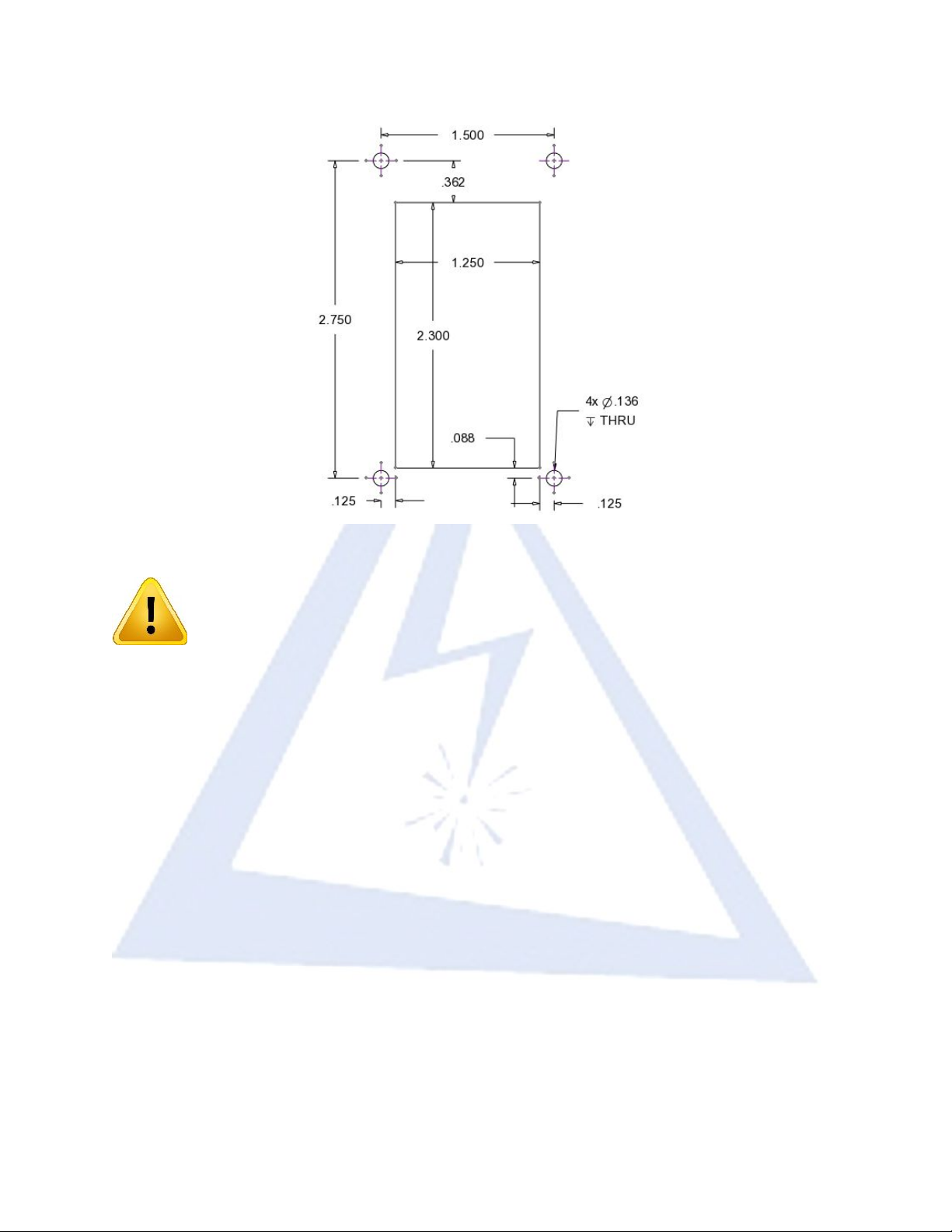
Remove the material of the instrument panel in accordance with the cutout
provided. Be advised that the drawing scale is not 1:1. All dimensions are in
inches.
Figure 3: Configuration A Cutout Dimensions
Electroair Acquisition Corp. IM EA-15000 Page 8 of 10
Revision 01 Prepared by: EAC 02/04/2020
Figure 4: Configuration B Cutout Dimensions
CAUTION: Before cutting or drilling verify space is clear behind the
instrument panel.
CAUTION: Use extreme care as to not damage any wiring,
instruments, structural, and fuel lines.
CAUTION: The connectors and connecting hardware for the starter switch are
small. Take extreme care not to lose them.
CAUTION: Ensure electrical connectors are tight on switch connections. Ensure
wires will not pull out of any electrical connections.
Left Mag Switch
o Connect ground to GND.
o Connect the P-Lead from the Left Magneto to P-LEAD.
Right Mag Switch
o Connect ground to GND.
o Connect the P-Lead from the Right Magneto to P-LEAD.
Starter Switch
o Use this switch as the Start Switch.
o Connect lead from starter terminal of ignition switch to terminal 1.
o Connect B+ to terminal 2.
Insulate any exposed electrical connections in accordance with 43.13-1B Change
1 section 11-159.
Insert ignition/starter switch panel into instrument panel and screw down using
standard hardware.

Electroair Acquisition Corp. IM EA-15000 Page 9 of 10
Revision 01 Prepared by: EAC 02/04/2020
Figure 5: Configuration A and B Back Surfaces
4. Final Installation Steps:
CAUTION: If using a non-impulse coupled magneto aka direct
drive magneto aka non-starting magneto, update pilot checklist/
POH to have MAG switch in OFF position during starting.
Start the aircraft per the AFMS and perform a ground run-up.
o Check for proper starter function.
o Check for proper RPM drop on Left Magneto.
o Check for proper RPM drop on Right Magneto.
If the aircraft passes, then return to service.
If the aircraft fails, then verify that all of the connections are correct and
competent and that no other wires were damaged during the install. Repeat the
start-up process.
If the aircraft fails a second time, contact the factory for support. (248-674-3433
or sale[email protected])
Electroair Acquisition Corp. IM EA-15000 Page 10 of 10
Revision 01 Prepared by: EAC 02/04/2020
Glossary and Abbreviations:
AD(s) – Airworthiness Directive(s)
AFM – Aircraft Flight Manual
AFMS – Aircraft Flight Manual Supplement
ALS – Aircraft Limitations Section
AML – Approved Model List
APU – Auxiliary Power Unit
BTDC – Before Top Dead Center
CFR – Code of Federal Regulations
CSTW – Crank Shaft Trigger Wheel
EIS – Electronic Ignition System
FAA – Federal Aviation Administration
Ignition Timing – is the process of setting the angle relative to piston position and
crankshaft angular velocity that a spark will occur in the combustion chamber near the
end of the compression stroke.
IAW – In Accordance With
ISSP – Ignition/Starter Switch Panel
MAG – magneto
MAP – Manifold Absolute Pressure
May/Should – an optional requirement
MTH – Mag Timing Housing
Must/Shall – a mandatory requirement
RPM – Revolutions per Minute
POH – Pilot’s Operating Handbook
STC – Supplemental Type Certificate
TDC – Top Dead Center
Table of contents
Other Electro-Air Control Panel manuals


