3
The boiler must be connected by a qualified
professional. Strict compliance with these
usage, electrical connection and start up
instructions is a precondition for the correct
operation of the boiler.
1. GENERAL
1.1 Presentation
The E control panel with an Thermatic regulator
(user-system interface) to be fixed to the wall or
integrated into the boiler control panel can be used
for:
-automatic operation of heating when the ambient
temperature has been reached
-control of heating as a function of the outside tempe-
rature.
-regulation and programing of domestic hot water pro-
duction (if it is present) with or without priority
-providing a frost free room temperature if the home is
empty. The duration of this period may be programed
up to 99 days.
The basic delivery of the T control panel comprises
-1Tcontrol panel
- 1 Thermatic regulator (user-system interface) with
support to be installed in the chosen room or to be incl-
uded in the control panel.
- 1 boiler sensor measuring the water temperature in
the boiler
- 1 external sensor
Options
The following option can be ordered:
-domestic hot water sensor (package FM 45).
1.3 Technical characteristics
The T control panel can be used to program and regu-
late the room temperature as a function of the outside
temperature by controlling the burner. The boiler
thermostat must be set to a sufficiently high tempera-
ture for automatic regulation to operate correctly
The safety thermostat with auto reset (adjusted to
110°C/230°F) maintains operating safety.
In the case of domestic hot water (d.h.w.) production,
domestic hot water is regulated by the regulator acting
on the load pump giving priority to heating of domestic
hot water.
When a request is made for heating domestic hot
water, the domestic hot water priority stops the burner
and the d.h.w. load pump and stops the heating pump.
Under summer conditions, the boiler is not kept hot
between two domestic hot water loads. The domestic
hot water temperature is measured by the d.h.w.
sensor.
The regulator includes the possibility of a "antilegio-
nellosis" protection.
1.2 Operating principle
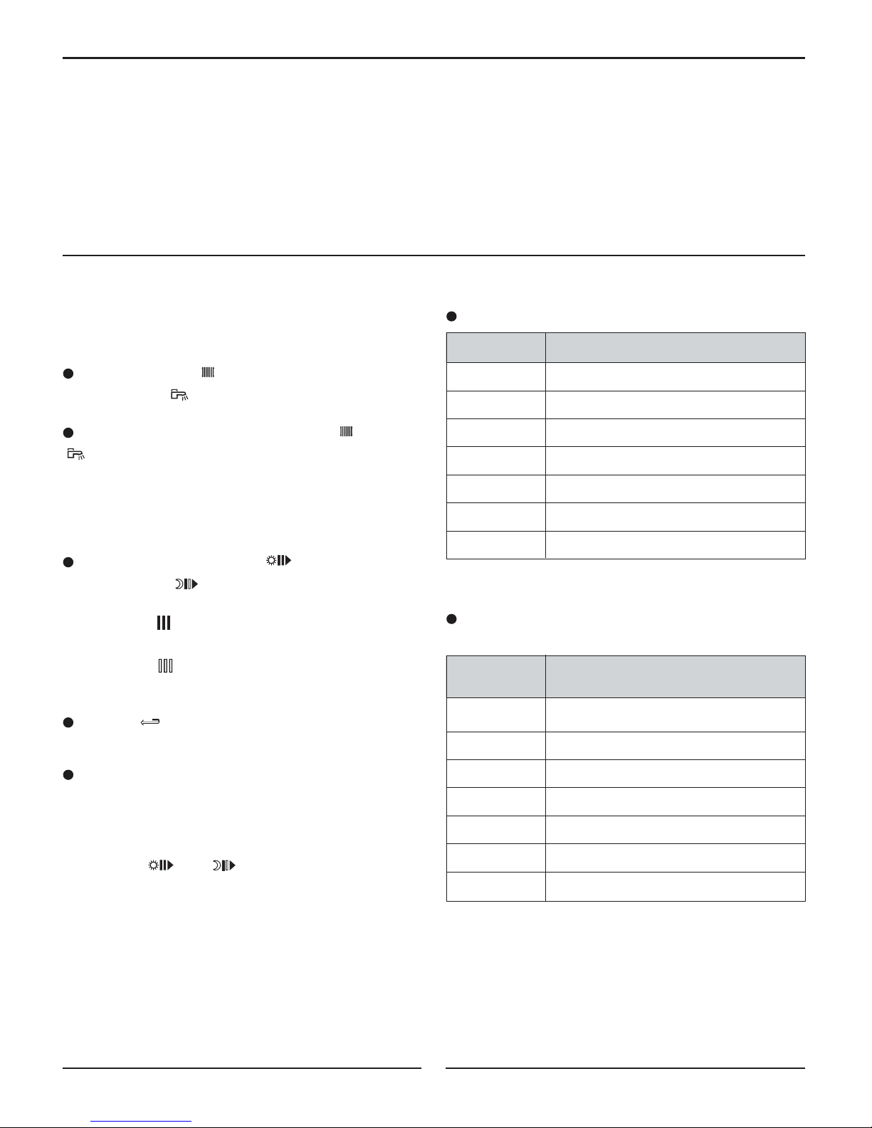
Temperature Resistance
in °C / °F in Ohm
- 20°C / -4°F 2 392 Ω
- 16°C / 3°F 2 088 Ω
- 12°C / 10°F 1 811 Ω
- 8°C / 18°F 1 562 Ω
4°C / 25°F 1 342 Ω
0°C / 32°F 1 149 Ω
Temperature Resistance
in °C / °F in Ohm
4°C / 39°F 984 Ω
8°C / 46°F 842 Ω
12°C / 54°F 720 Ω
16°C / 61°F 616 Ω
20°C / 68°F 528 Ω
24°C / 75°F 454 Ω
-Electrical power supply: 120V - 60 Hz
-Clock operating capacity: 2 years minimum
-Resistance of the external sensor in Ω (option)-Value of water sensors in Ω
Temperature Resistance
in °C / °F in Ohm
0°C / 32°F 32 014 Ω
10°C / 50°F 19 691 Ω
20°C / 68°F 12 474 Ω
25°C / 77°F 10 000 Ω
30°C / 86°F 8 080 Ω
40°C / 104°F 5 372 Ω
Temperature Resistance
in °C / °F in Ohm
50°C / 122°F 3 661 Ω
60°C / 140°F 2 535 Ω
70°C / 158°F 1 794 Ω
80°C /176°F 1 290 Ω
90°C / 194°F 941 Ω
- EC-10, EC-20 and EC-100.