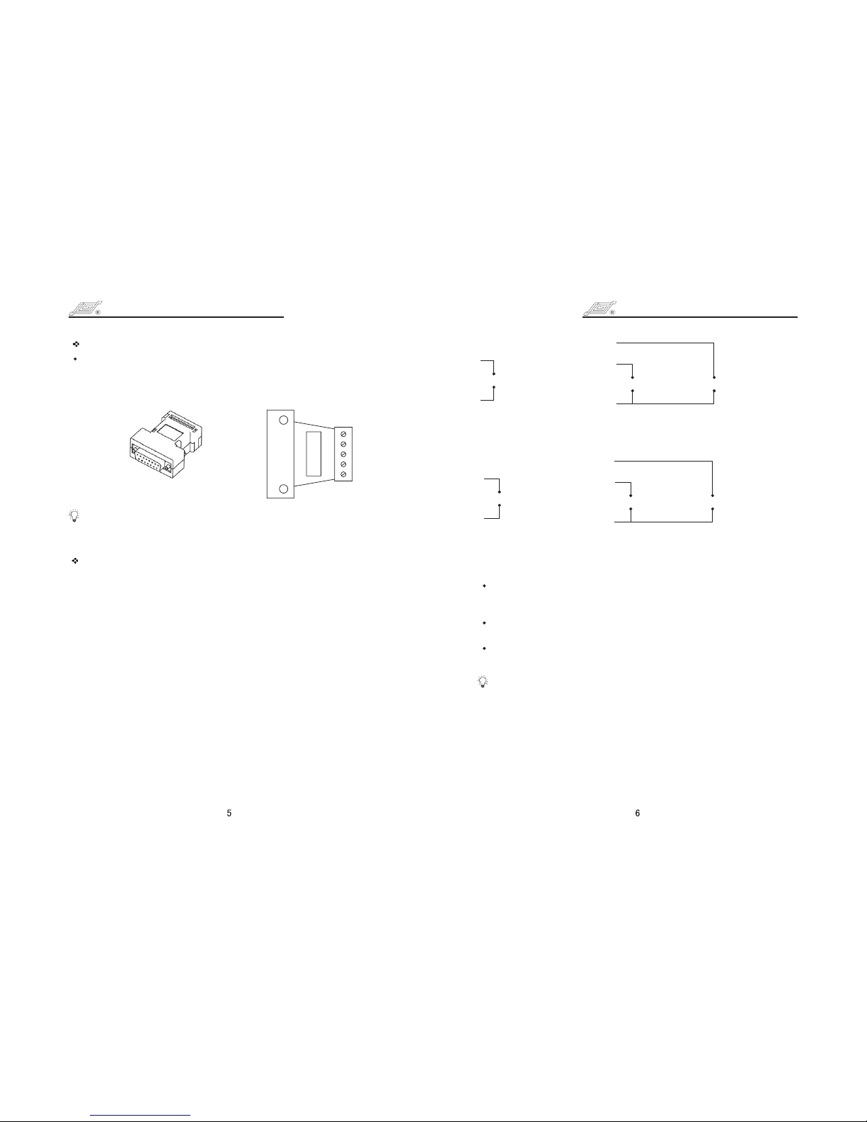
Terminal Definition of Standard External Control Module
4 20 mA, 0 - 5V, 0 10V
analog input control the
speed
--
0 5V, 0 10V, 4 20mA
External Control Input Module Connection Diagram
-- -
+
-
1
4
1# is analog input in 4 - 20 mA, 0 5 V, 0 10 V external control
modules. Control the speed of the pump.
2# is external control start/stop input. When connected to COM, the
pump runs; When connected to high level (5 10 V), the pump
stops.
3# is external control cw/ccw input. When connected to COM, the
pump rotates clockwise; When connected to high level, the pump
rotates counter clockwise.
4# is analog ground (AGND) in 4 20 mA, 0 5 V, 0 10 V external
control modules; 4# is pulse input in pulse input external control
modules. Control the speed of the pump. 10 KHz is corresponding
to the max.speed.
5# is the COM of external control direction and start/stop signal
input; It's also the COM of pulse signal input in pulse input
external control module.
--
-
---
CC/CCW Signal
(5V TTL)
Start/Stop Signal
(5V TTL)
+
-
3
5
+
-
2
0 10 kHz Pulse Signal Input Connection Diagram-
0 - 10 kHz pulse input
control the speed
+
-
4
5
Analog Control
Show as below for external control module. If you need external
control function you just insert the external control module to the
external control interface which is on the rear panel of the pump.
Connect the corresponding control signal wire.
Note:
Four kinds of standard external control module need to be ordered
separately according to special requirements.
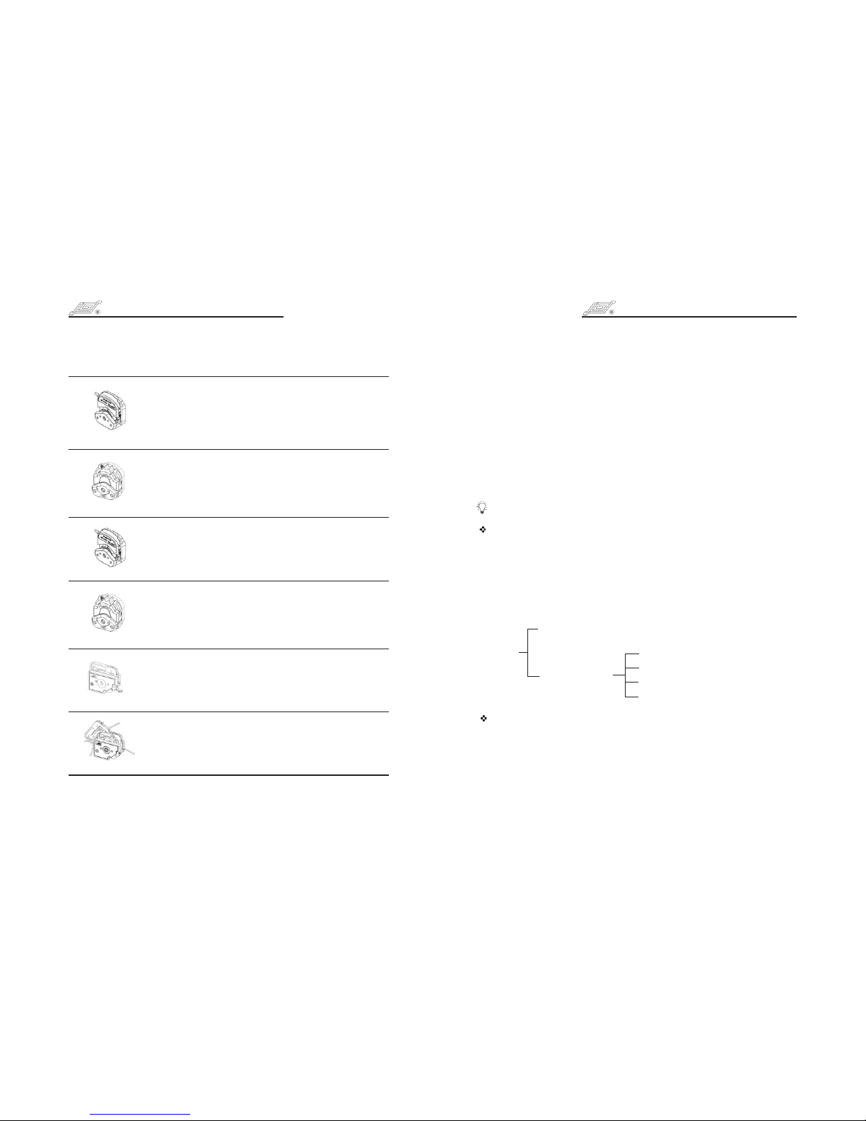
External Control Model
5
4
3
2
1
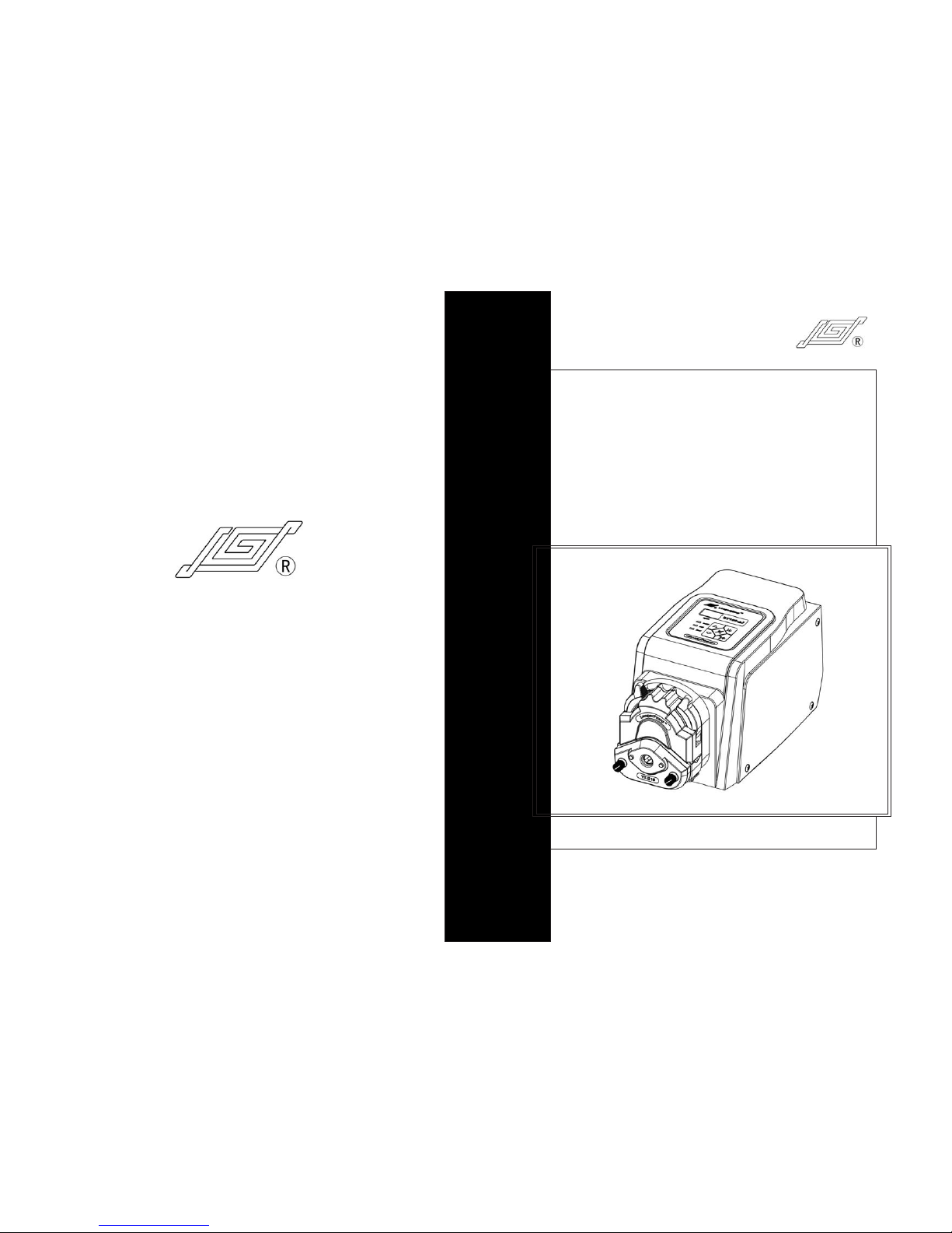
BT100-2J OPERATING MANUAL BT100-2J OPERATING MANUAL
CC/CCW Signal
(5V TTL)
Start/Stop Signal
(5V TTL)
+
-
3
5
+
-
2
Maintenance
When the pump is idle, we recommend you to release the tubing
from pressure. This helps to protect the tubing from unnecessary
strain and prolongs its service life
Keep rollers clean and dry. This will prolong the service lives of
tubing and pump head.
The surface of drive and the pump head are not organic solvent
and aggressive liquids resistant. Please pay attention when using.
Note:
If a trouble happens, please contact us or our dealers.
Warranty
The warranty period for this product is one year. If repair or
adjustment is necessary within the warranty period, the problem
will be corrected at no charge if it is not due to misuse or abuse on
your part, as determined by the manufacturer. Repair costs
outside the warranty period, or those resulting from product
misuse or abuse, may be invoiced to you.