LONGER WT600-1F User manual

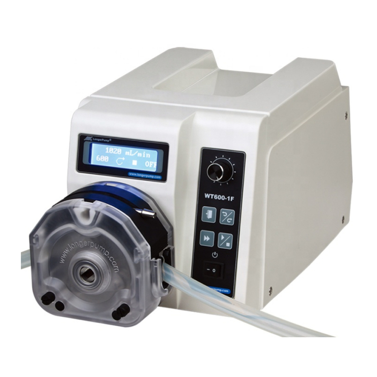
WT600-1F Peristaltic Pump
Baoding Longer Precision Pump Co.,Ltd.
WT600-1F PERISTALTIC PUMP
OPERATING MANUAL

1
2
2
3
3
3
4
5
5
6
6
6
6
7
7
8
8
8
8
9
9
9
9
10
11
11
11
12
14
14
15
15
15
16
IMPORTANT INFORMATION:
Please read operation manual carefully before operation.
WARNINGS:
Tubing breakage may result in fluid sprayed from pump. Use appropriate
measures to protect operator and equipment. Please check the tubing
frequently and change the tubing in time.
If the power line or the plug is worn or damaged please pull out the plug (Hold
the plug not the power line when pulling out).
Please shut down the power supply and pull out the plug when meet below
circumstance :
The fluids splash on the body of the pump.
You think the pump needs to be maintained or repaired.
Please shut down the power supply before install the external control
equipments.
WT600-1F OPERATING MANUAL
Table of Contents
Instruction
Operation Panel
Basic Operation
Running Interface
Flow Rates Display
Dispensing Display
Acceptable Pump Head and Tubing
Changing the Pump Head
Menu Diagram
System Setting
Pump Head and Tubing Setting
External Control Setting
Pump address Setting
Footswitch Setting
Back Suction rpm Setting
Control Mode
Dispensing Setting
Dispensing Volume
Copy No.
Flow Rates
Pause Time
Calibration
Flow Rates Calibration
Dispensing Volume Calibration
Operation Procedure
Flow Rates Mode
Dispensing Mode
External Control Input
External Control Output
Footswitch Function
Communication Function
Maintenance
Warranty
Technical Specification
WT600-1F OPERATING MANUAL

1
Pump Head
Drive
Power Socket
External Control Input Por t
Infuse Holder
External Control Output Por t
Introduction
Acceptable pump heads for WT600-1F are YZ1515x, YZ2515x, YZII15, YZII25,
DG15-24, KZ25, BZ25 and DMD25. The pump delivers flow rates from 0.7 to
6000 mL/min and dispensing volume is from 0.1 mL to 9900 mL. Combining
128 × 32 LCD display with membrane keypad and rotary coded switch makes
the operation easy and prompt. The speed can be adjusted manually or
automatically through external control interface.
Please see page 12 for detailed external control function.
Make sure the power line of the pump is grounded reliably to protect the
operator in humid condition.
Operation Panel
2
Star t/Stop Key
Exit Key
Direction Key
Prime Key
Knob
LCD Display
Power Switch
Basic Operation
Start/Stop Key
Press the Start/Stop Key to star t or stop the pump.
Direction Key
Press the Direction Key to change the rotation direction of the pump.
Knob
Function 1: Turn the Knob to adjust the flow rates in flow rates display state.
Function 2: Turn the Knob to select the menu and set the parameters, press
Knob for confirmation in menus selection state.
Prime Key
In common state, press the Prime Key to enter prime state when the pump runs
at full speed for empting, filling and rinsing operation; Press the Prime Key
again to return to common state. In prime state, other keys are invalid.
Exit Key
Function 1: Cancel current operation and return to previous menu.
Function 2: In dispensing mode, press Exit Key to switch different dispensing
parameters display.
Power Switch
Turn on or off the pump.
WT600-1F OPERATING MANUAL WT600-1F OPERATING MANUAL

b.
c. d.
e.
Running Interface
Turn on the pump, the pump is initialized first, then display the running interface.
a.
3 4
7.000 mL/min
50.0
INT
g.
f.
b.
c.
d.
h.
c.
d.
=
Single Channel 0.7- 42
Single Channel 2.7-162
Single Channel 5.1-306
Single Channel 8.2-492
Single Channel 17-1020
Single Channel 29-1740
Single Channel 38-2280
Single Channel 17-1020
Single Channel 29-1740
Single Channel 17-1020
Single Channel 29-1740
Single Channel 38-2280
Single Channel 50-3000
30-1800
58-3500
83-5000
100-6000
29-1740
8.2-492
20-1150
30-1800
4.2-150
23-800
42-1500
68-2400
84-2950
120-4170
(1,2)×YZ1515x
(1,2)×YZⅡ15
(1,2)×YZ2515x
(1,2)× YZⅡ25
KZ25
BZ25
DG15-24
DMD25
#
15
#
24
#
15
#
24
#
35
#
36
#
15
#
24
#
35
#
36
#
24
#
16
#
25
#
17
#
119
#
120
#
15
#
24
#
35
#
36
#
13
#
14
#
19
#
16
#
25
#
17
#
18
The running speed range of DMD25 is less than 350 rpm.
Pump heads and tubing can be selected referring to above table. It is necessary to select
suitable pump heads and tubing to get higher flow rates and dispensing accuracy. We
suggest the needed flow rates are in the 20% to 80% of ref. flow rates range.
Flow Rate Display
Dispensing display: Dispensing parameters are displayed in two interfaces,
Press Exit Key to switch these two interfaces.
a. Current flow rates: Display current flow rates. Turn the Knob to increase or
decrease the flow rates.
b. Current speed: Display current speed. The speed will change when adjusting
the flow rates.
c. Running direction: Indicate the direction of the pump. Means clockwise and
Means counter clockwise.
d. Running status: means the pump is running; means the pump stops;
Means pump pauses. Press Start/Stop Key to control the running state of
the pump.
e. Control mode: INT means the pump is controlled internally; V means the pump
is controlled by external analog voltage signal; mA means the pump is
controlled by external analog current signal; Hz means the pump is controlled
by external 0 -10 KHz pulse signal. Off means shutting off the external control
function by setting menu;
f. Dispensing volume: Display dispensing volume in dispensing mode.
g. Copy number: Display copy number under dispensing mode.
h. Dispensing time: Display the dispensing time. When the dispensing procedure
star ts, the dispensing time will be counted down. Adjust the flow rates to
change the dispensing time in dispensing parameters setting inter face.
Vol: 13.0 mL
Copy: 9999
Disp T.: 79.0"
100 RPM
Acceptable Pump Heads and Tubing (Table 1)
Pump Heads Ref. Flow Rates(mL/min)
Tubing (mm)
WT600-1F OPERATING MANUAL WT600-1F OPERATING MANUAL

6
5
Menu Diagram
Changing the Pump Head
The pump head is mounted on drive before the pump leaves the factory. Follow
below procedure for changing another pump head.
Loose the two M4 screws which connect the pump head and the drive.
Dismantle the pump head slightly.
Inser t the flat end of the pump head's shaft to the slot of drive's coupling.
Make the location hole of the pump head match the location pin of the drive.
Inser t the two mounting screws into the mounting holes of the pump head.
Then tighten the mounting screws to connecting hole of drive. (For more
information, please refer to pump head's operation manual)
Turn off the power supply before changing the pump head.
1.
2.
3.
VOL: 0.25mL
Copy: 991
Running Interface
1.System Setting
2.Control Mode
3.Disp Setting
4.Calibration
1. Pump head&Tube
YZ1515 ID 0.80
2.Ext Cont. :ON
3.Address : 1
4.Footswitch :G
5.Back rpm :1.2"
Flowrate
Dispensing
Disp Vol:2.02mL
Copy No. :10
Flow:2.043mL/min
Pause rpm :1.0 "
Flowrate
Dispensing
1.System Setting
2.Control Mode
3.Disp Setting
4.Calibration
YZ1515 ID 0.80
YZ1515
YZ2515
Select Tubing ID
0.80 1.60 2.40
Ext Control :
ON OFF
Pump Address:
1
1.System Setting
2.Control Mode
1. Pump head&Tube
1.System Setting
2.Control Mode
2.Ext Cont. :ON
3.Address : 1
1.System Setting
2.Control Mode
2.Ext Cont. :ON
3.Address : 1
System Setting:
All the setting can not be done when pump is running.
Pump head and tubing setting
Press the Knob to highlight Pump Head & Tube line, press Knob again to enter
pump head selection interface, turn Knob to select the pump head, press the
Knob for confirmation and enter tubing selection interface, turn Knob to select
the tubing, press Knob for confirmation and return to pump head selection
interface. Press Exit Key to return to previous menu.
External Control setting
Set the pump to enable the external control or not.
On: Enable external control (0 - 5 V, 0 - 10 V, 4 - 20 mA, 0 - 10 KHz)
Off: Disable external control
Set the external control
Press and turn Knob to highlight the external control line. Press Knob to enter
next interface, turn Knob to select On or Off, press Knob for confirmation. Press
Exit Key to return to previous menu.
Press and turn Knob
Press and turn Knob
Address setting:
When control computer controls many pumps through RS485 interface, it must
identify each pump's I.D. This pump I.D. should be unique. It's the identification
of this pump. Maximum 30 pieces WT600-1F can be controlled through RS485
at the same time.
Setting the address
Press and turn Knob to highlight the address line. Press Knob again to enter next
interface, turn Knob to select Pump I.D. number, press Knob for confirmation.
Press Exit Key to return to previous menu.
WT600-1F OPERATING MANUAL WT600-1F OPERATING MANUAL

78
4.Footswitch:G
5.Back rpm :1.2"
Footswitch:
Gated Trigger
Back rpm :
1.2"
1.System Setting
2.Control Mode
1.System Setting
2.Control Mode
4.Footswitch:G
5.Back rpm :1.2"
Footswitch Setting
Footswitch has two kinds of working modes.
Trigger: Press footswitch, the pump star ts running; Press footswitch again,
the pump stops.
Gated: The pump runs as long as the footswitch is pressed.
Set Footswitch
Press and turn Knob to highlight the footswitch line. Press Knob to enter next
interface, turn Knob to select Trigger or Gated, press Knob for confirmation.
Press Exit Key to return to previous menu.
The pump identifies the Longer Footswitch automatically. When the pump
connects the footswitch, the Star t/Stop Key on operating panel is invalid no
matter the external control setting is on or off.
Press and turn Knob
Press and turn Knob
Back suction rpm (revolutions per minute) Setting
In dispensing and filling state, to prevent the liquids from dropping to cause
error when the filling pauses, the pump will back-turn to suck back the liquids.
The back turn angle is the same for each filling operations, it doesn't influence
the filling accuracy.
Set back suction rpm:
Press and turn Knob to highlight the back suction rpm line. Press Knob to enter
next interface, turn Knob to select back suction rpm, press Knob for
confirmation. Press Exit Key to return to previous menu.
Flowrate
Dispensing
Disp Vol:2.02mL
Copy No. :10
Disp Vol:
2.02 mL
Copy No.:
10
1.System Setting
2.Control Mode
1.System Setting
2.Control Mode
3.Disp Setting
4.Calibration
1.System Setting
2.Control Mode
3.Disp Setting
4.Calibration
Disp Vol:2.02mL
Copy No. :10
Control Mode
The pump has two kinds of working mode: Flow Rates and Dispensing.
Set Control Mode:
Press and turn the knob to highlight control mode line. Press Knob to enter next
interface, turn Knob to select control mode, press Knob for confirmation. Press
Exit Key to return to previous menu.
Dispensing Setting
Before dispensing process, the parameters including pump head, tubing, back
suction rpm, dispensing volume, copy number, flow rates, pause time, etc. must
be set.
Dispensing Volume: the volume that the pump dispenses between every time
interval.
Press and turn Knob to highlight dispensing setting line. Press Knob to highlight
dispensing volume line. Press Knob again to highlight the value of the volume.
Turn Knob to select dispensing volume, press Knob for confirmation. Press Exit
Key to return to previous menu.
Copy No.: the total filling number in dispensing mode. Its range is from 0 to 9999.
Press and turn Knob to highlight copy number line. Press Knob to enter next
interface. Turn Knob to select copy number, press Knob for confirmation. Press
Exit Key to return to previous menu.
If the copy no. is “0”, the dispensing process of the pump will continue until
press Start/Stop Key or shut off the pump to stop dispensing.
WT600-1F OPERATING MANUAL WT600-1F OPERATING MANUAL

910
Flow:2.043mL/min
Pause T. :1.0 "
Pause Time :
1.1 "
Flowrate
Dispensing
Test T.: 0.5 ’
Cal Vol :132.3μL
Run Time :30"
Act. Vol :132.3μL
1.System Setting
2.Control Mode
3.Disp Setting
4.Calibration
1.System Setting
2.Control Mode
3.Disp Setting
4.Calibration
1.System Setting
2.Control Mode
3.Disp Setting
4.Calibration
Flow:2.043mL/min
Pause T. :1.0 "
Flow:2.043mL/min
Pause T. :1.0 "
Test T.: 0.5 ’
Cal Vol :132.3μL
Test T. : 0.5 ’
Cal Vol :132.3μL
Test T. :30"
Cal Vol :133.0μL
Flow rates: Adjusting the dispensing flow rates can change the dispensing time.
Press and turn Knob to highlight dispensing flow rates line. Press Knob to enter
next inter face, turn Knob to select suitable flow rates, press Knob for
confirmation. Press Exit Key to return to previous menu.
Press
Knob
Pause Time: Time Interval between every dispensing operation.
Press and turn Knob to highlight pause time line. Press Knob to enter next
interface. Turn Knob to select pause time, press Knob for confirmation. Press
Exit Key to return to previous menu.
Calibration
Pump should be calibrated when flow rates or dispense volume is beyond the
tolerance. Flow rates and dispensing volume can be calibrated separately in
different applications.
Flow Rates Calibration
Press and turn Knob to highlight calibration line. Press Knob to enter next
interface. Turn Knob to select Flowrate. Press Knob to highlight test time line.
Press Knob again to highlight the value of time. Turn Knob to select test time
(its range is from 30 to 1800 seconds), press Knob for confirmation. Press
Exit Key to return to previous menu.
Press Start/Stop Key, the LCD displays running time and actual volume.
Running time counts down.
Turn Knob to input actual test volume. Press Knob for confirmation. The
calibration operation can be repeated.
Turn Knob to input
Actual Volume
If the actual volume is known in advance, enter the calibration interface and
input the actual volume directly.
Disp Vol :2.02mL
Disp T. :60.5"
Disp T. :60.5"
Act Vol :2.020 mL
Act Vol :
2.02 mL
1.System Setting
2.Control Mode
3.Disp Setting
4.Calibration
Flowrate
Dispensing
Test T. : 0.5 ’
Cal Vol :132.3 μL
Test T. : 0.5 ’
Cal Vol :132.3 μL
Act Vol :
133.0 μL
Flowrate
Dispensing
Disp T. :60.5"
Act Vol :2.040 mL
1.System Setting
2.Control Mode
3.Disp Setting
4.Calibration
Flowrate
Dispensing
Disp Vol :2.02mL
Disp T. :60.5"
If the actual volume is known in advance, enter the calibration interface and
input the actual volume directly.
Turn Knob to input
Actual Volume
Dispensing Volume Calibration
The parameters can not be changed under dispensing volume calibration
operation. The defaulted parameters are the parameters set under Dispensing
Setting.
Pump stops under dispense mode, press and turn Knob to highlight calibration
line. Press Knob to enter next interface. Turn Knob to select Dispense.
Press Start/Stop Key, the LCD displays running time and actual volume.
Running time counts down.
Turn Knob to input actual volume. Press Knob for confirmation.
Turn Knob to input
actual volume
Turn Knob to input
actual volume
WT600-1F OPERATING MANUAL WT600-1F OPERATING MANUAL

11 12
Select pump head
and tubing refer to
the table of page 4
Dispensing mode operation procedure
Confirm the
volume to be
dispensed
Press Exit Key to
return to running
inter face
Operation Procedure
Before running the pump, select pump head and tubing refer to “Acceptable
Pump Head and Tubing (Table 1)”. Thick wall tubing is preferred for longer
service life.
Flow rates mode operation procedure
Confirm the flow
rates of the fluid
which need to be
pumped
Press Knob to
enter System
Setting inter face
to set pump head
and tubing
Enter Control
Mode interface to
select Flow Mode
Press Exit Key to
return to running
inter face, turn
Knob to select
needed flow rates
Press Knob to
enter calibration
selection inter face
and select
Flowrate when
calibration is
needed
Set Test Time,
press Start/Stop
to star t the pump.
Input the actual
volume
Press Exit Key to
return to running
inter face
Select pump
head and tubing
refer to the table
of page 4
Press Knob to
enter System
Setting inter face
to set pump head
and tubing
Set Back
Suction rpm
Enter control
mode interface
to select
Dispensing
Enter Dispense
Setting inter face
to set all the
dispensing
parameters.
Press Knob to
enter calibration
selection
inter face and
select Dispensing
when calibration
is needed
Press Start/Stop
to star t the pump.
Input the actual
volume
External Control Input
Analog Signal Input function
Communication Control
The pump can connect to control computer (computer, PLC, SCM) through
RS485 serial communication module (shown as below). Please contact Longer
Company for communication protocol.
COM
B
A
Set the “External Control” in “on” state. External control module is shown as below.
Five kinds of standard external control module need to be ordered separately
according to special requirements.
5
4
3
2
1
External Control Module
Analog Control
4 - 20 mA Speed Control
0 - 5 V Speed Control
0 - 10 V Speed Control
0 - 10 KHz Speed Control
External Control
DB15
Communication Control RS485
WT600-1F OPERATING MANUAL WT600-1F OPERATING MANUAL

13 14
Terminal Definition of Standard External Control Module
Analog input in 4 - 20 mA, 0 - 5 V, 0 - 10 V external control
modules. Control the speed of the pump.
External control star t/stop input. When connected to COM, the
pump runs; When connected to high level, the pump stops.
External control cw/ccw input. When connected to COM, the pump
rotates clockwise; When connected to high level, the pump rotates
counter clockwise.
Analog ground (AGND) in 4 - 20 mA, 0 - 5 V, 0 - 10 V external
control modules;
Pulse input in pulse input external control modules. Control the
speed of the pump. 10 KHz is corresponding to the max.speed.
The COM of external control direction and star t/stop signal input;
It's also the COM of pulse signal input in pulse input external
control modules.
Terminal 1
Terminal 2
Terminal 3
Terminal 4
Terminal 5
Pump is equipped with output por t in order to monitor the status of pump.
Please see below “External Control Output Por t Pins Diagram: DB9”. Output
signal adopts optoelectronic isolation circuit. A pull-up resistor and power
supply are needed when using.
Pins Definition
External Control Output
External Control Output Por t Pin Diagram: DB9
Footswitch Function
Connect Footswitch to r control Input Por t to control Star t/Stop of pump. emote
It can be set according to actual application.
Pin 1
Pin 2
Pin 8
Pin 4, 6, 7
Star t/Stop output. Pump outputs low level when it runs; pump
output high level when it stops.
Direction output. Pump output low level when it runs clock wise;
pump output high level when it runs count clock wise.
Pulse output, 0 - 600 rpm corresponding to 0 - 10 kHz.
COM
Footswitch is optional accessories. It can only control the start and stop of the
pump. The speed and direction of the pump are controlled by membrane keypad
and knob on the operation penal.
Connection Diagram for Footswitch
Shor t terminal 5 and 11; shor t
terminal 12 and 13; terminal 8
connects footswitch;
terminal 11 connects footswitch.
1234 5 6 7 8
910 11 12 13 14 15
4 - 20 mA, 0 - 5V, 0 - 10V analog
input control the speed
0 - 5V, 0 - 10V, 4 - 20mA
External Control Input Module Connection Diagram
+
-
1
4
CC/CCW Signal
(5V TTL)
Star t/Stop Signal
(5V TTL)
+
-
3
5
+
-
2
0 - 10 kHz Pulse Signal Input Connection Diagram
0 - 10 kHz pulse input control
the speed
+
-
4
5
CC/CCW Signal
(5V TTL)
Star t/Stop Signal
(5V TTL)
+
-
3
5
+
-
2
WT600-1F OPERATING MANUAL WT600-1F OPERATING MANUAL

15 16
Communication Function
WT600-1F can connect to the control computer (computer, PLC, SCM) through
RS485 serial communication interface. Max. 30 pumps can be controlled by a
control computer.
1. The pump ID which connects to the control computer through RS485 serial
communication interface must be unique to prevent the communication
error.
2. Please contact Longer Company for communication protocol.
Maintenance
When the pump is idle, we recommend you to release the tubing from pressure.
This helps to protect the tubing from unnecessary strain and prolongs its
service life
Keep rollers clean and dry. This will prolong the service lives of tubing and
pump head.
The sur face of drive and the pump head are not organic solvent and aggressive
liquids resistant. Please pay attention when using.
If a trouble happens, please contact us or our dealers.
Warranty
The warranty period for this product is one year. If repair or adjustment is
necessary within the warranty period, the problem will be corrected at no
charge if it is not due to misuse or abuse on your par t, as determined by the
manufacturer. Repair costs outside the warranty period, or those resulting
from product misuse or abuse, may be invoiced to you.
Technical Specifications
Functions
Acceptable Pump Head: YZ1515X, YZ2515X, YZII15, YZII25, DG15-24, KZ25, BZ25, DMD25
Operation Mode: Membrane keypad and Knob
Direction Control: CW and CCW, reversible
Prime: Full speed for fast filling and emptying
Back Suction: Prevent the liquid from dropping
Display: 128×32 graphic LCD displays all the information
External Control Input: Control Star t/Stop, direction and flow rates under flow rates mode
Footswitch: Control Star t/Stop of the pump
External Control Output: Output the signals of Star t/Stop, direction and speed
Communication: Communicate with control computer
Flowrate Function: Deliver fluid at set flow rates
Dispensing Function: Set dispensing volume, copy number and pause time, etc.
Memory Function: Store all the running information automatically
Calibration: Acquire higher accuracy
Cooling Mode: Heat-emitting fan
Specification
Speed: 10 - 600 rpm
Flow Rates: 0.7mL/min to 6000 mL/min
Dispensing Volume: 0.01mL to 9.99L
Copy Number: 0 to 9999 "0" means continuous running
Pause Time: 0.1s to 99.9min
Back Suction rpm: 0 to 9.9
External Control Input: Star t/Stop control, direction control, flow rates control (0 - 5V ,
0 - 10V , 4 - 20 mA , 0 - 10KHz optional )
External Control Output: Star t/Stop, direction, 0 - 10 kHz speed signal, OC gate output
Communication Interface: RS485
Applicable Power: AC 90 - 264V 50Hz/60Hz
Power Consumption: <150W
Operating Condition: Temperature 0 to 40 °C
Relative humidity < 80%
Dimension (L × W × H): 292.3 × 185 × 180.5 (mm)
Weight: 5.2 kg
IP Rating: IP 31
WT600-1F OPERATING MANUAL WT600-1F OPERATING MANUAL
Table of contents
Other LONGER Water Pump manuals