LORD G-Link-200 User manual

LORD QUICKSTARTGUIDE
G-Link®-200
Ruggedized High-Speed Triaxial Accelerometer Node
The G- Link- 200 wireless accelerometer node features an on- board triaxial
accelerometer that allows high-resolution data acquisition at noise levels as low
as 25 or 80 µg√Hz.The G-Link-200 can output continuous waveform data, or one
of four derived channels, including Velocity (IPSrms), Amplitude (Grms and Gpk-pk)
and Crest Factor, allowing long-term monitoring of key performance indicators
while maximizing battery life.
To acquire sensor data, the G-Link- 200 is used with a LORD Sensing data
gateway such as the WSDA-101 or WSDA-1500 Base. G-Link-200 sensor nodes
come with the following components.
Item Description Quantity
AG-Link-200 1
B½ AA, 3.6 V Lithium Batteries 3
Table 1 - G-Link-200 Components List
The G-Link-200 LEDs indicate operational modes showing when the node
is booting up, idle and waiting for a command, sampling, resynchronizing,
or if there is an error.
Indicator Behavior Node Status
Device
status
indicator
OFF Node is OFF
Rapid green flashing
on start-up Node is booting up
1 (slow) green pulse per
second
Node is idle and waiting for a
command
1 green blink every 2 seconds Node is sampling
Blue LED during sampling Node is resynchronizing
Red LED Error or low battery
Table 2 - Indicator Behaviors
Wireless Simplicity, Hardwired Reliability™

SYSTEM OPERATION
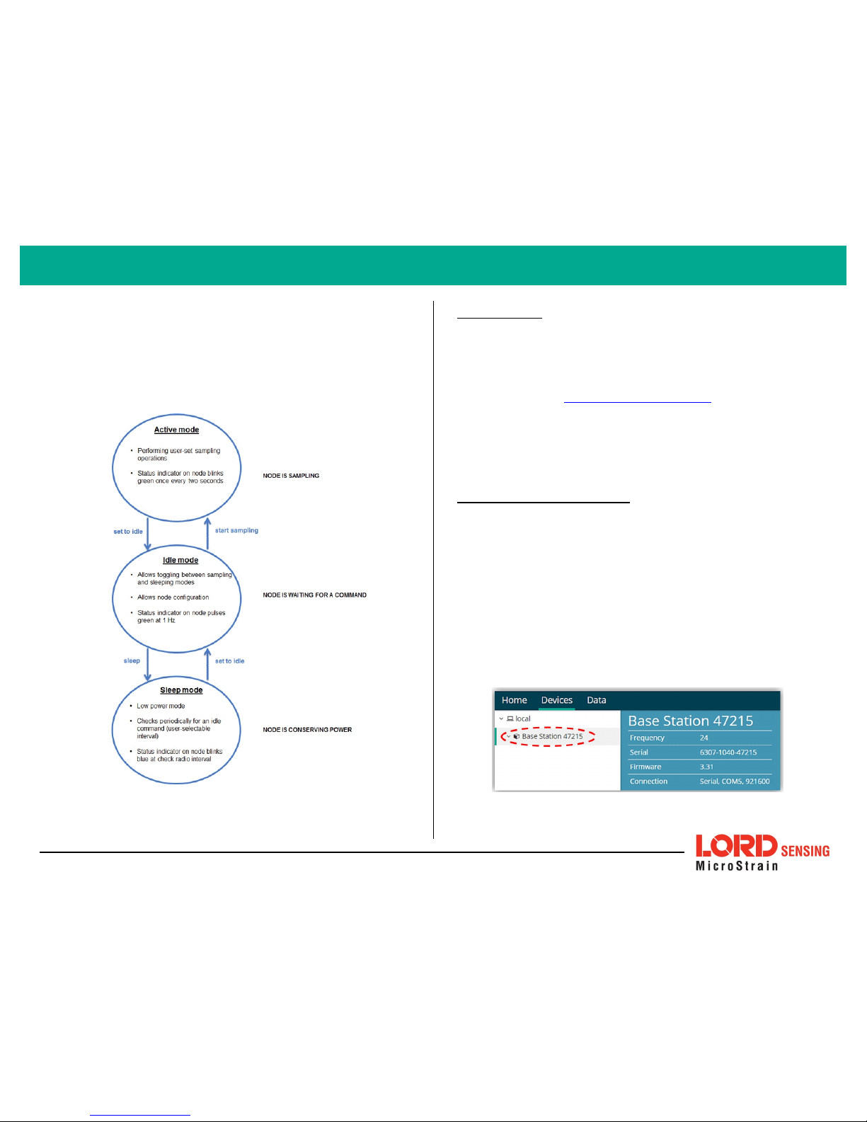
Sensor nodes have three operational modes:
active
,
sleep
, and
idle
. When the
node is sampling, it is in active mode. When sampling stops, the node is switched
into idle mode, which is used for configuring node settings, and allows toggling
between sampling and sleeping modes. The node will automatically go into the
ultra low-power sleep mode after a user-determined period of inactivity. The
node will not go into sleep mode while sampling.
Figure 1 - Node Operational Modes
1. Install Software
Install the SensorConnect software on the host computer before connecting any
hardware. The SensorCloud web platform is also available for data visualization
and analysis, and it is accessed by logging onto the SensorCloud website. The
SensorConnect software is available on the LORD Sensing website for free
download:
http://www.microstrain.com/software
SensorCloud is an optional data collection, visualization, analysis, and remote
management tool. It is based on cloud computing technology and is accessed
directly from a web connection. Automatic, real-time data collection is available
through Ethernet gateways, such as the WSDA- 1500. Data files can also be
uploaded. . For more information, see Connect toSensorCloud on page 1.
2. Establish Gateway Communication
Drivers for the USB gateways are included the SensorConnect software
installation. With the software installed, the USB gateway will be detected
automatically whenever the gateway is plugged in.
1. Power is applied to the gateway through the USB connection. Verify
the gateway status indicator is illuminated, showing the gateway is
connected and powered on.
2. Open the SensorConnect software.
3. The gateway should appear in the Controller window automatically
with a communication port assignment. If the gateway is not
automatically discovered, verify the port is active on the host
computer, and then remove and re-insert the USB connector.
Figure 2 - USB Gateway Communication
2
G-Link®-200 Wireless Accelerometer Node Quick Start Guide

3. Connect to Nodes
Several methods can be used in SensorConnect to establish communication with
the nodes: the automatic node discovery feature, manually entering the node
address, and scanning transmission frequency and node address ranges.
A. Add Node Via Node Discovery
If the base and node are on the same operating frequency, the node will
populate below the Base Station listing when powering on the G-Link-200.
Figure 3 - Node Discovered On Same Frequency
If a red circle with a number appears next to the Base Station, the node is
operating on a separate radio channel (see Connect to Nodes on page 3.).
Figure 4 - Node On Other Frequency
B. Add Node Manually
Adding a node manually requires entering the node address and its
current frequency setting.
From the Base Station, select the Manual Add Node tile, enter the Node
Address, last known Frequency (factory default is 15), and select Add
Node.
Figure 5 - Add Node By Address
If the node was successfully added, two confirmation messages will
appear and it will be listed under the Base Station.
Figure 6 - Add Node Confirmation
3
G-Link®-200 Wireless Accelerometer Node Quick Start Guide

If the node failed to be added, a failure message will appear. This means
the node did not respond to the base station which could indicate the
node is not in idle mode or it may be on another frequency. If "Add Node
Anyway" is selected, it will associate that node with the channel entered
but it is likely there will be a communication error. If the node was not in
idle, move the base station to the frequency of the node and issue a "Set
to Idle" command.
Figure 7 - Failure to Add Node
C. Move Node to Base Station Frequency
If a red circle with a number appears next to Base Station, the node is
operating on a separate radio channel. Select the Base Station and then
select the Nodes on Other Frequencies tile.
Figure 8 - Nodes On Other Frequencies
Highlight the new node being added and select Move Node to Frequency
(#).
Figure 9 - Move Node
4. Configure Node
Node settings are stored to non-volatile memory and may be configured using
SensorConnect. The configuration menus show the channels and configuration
options available for the type of node being used.
For this example, the G- Link- 200 is using the default settings found under
Configure > Hardware.
Input Range: ± 2 G's (acceleration)
Input Range: ± 10 G's (acceleration)
Low Pass Filter: 1000 Hz
Low Pass Filter: 800 Hz
High Pass Filter: Disabled
4
G-Link®-200 Wireless Accelerometer Node Quick Start Guide

Figure 10 - Node Configuration
5. Configure Sampling Setting and Start Data Acquisition
1. Left click on the Base Station > Sampling, and indicate the nodes to be
sampled by checking the box to the left of each node.
2. Under 3 Channels, select Raw Channels, ch1, ch2 and ch3 from the
drop down menu.
3. Under Sampling, select Sample Rate from the drop down menu, select
Continuously to sample indefinitely.
Figure 11 - Sampling Setting
4. Select Apply and Start Network.
5. Select Create QuickView Dashboard in the pop up window immediately
to create a dashboard of the new data.
Figure 12 - Quick View Dashboard
5
G-Link®-200 Wireless Accelerometer Node Quick Start Guide

G-Link®-200 Wireless Accelerometer Node Quick Start Guide
6. Replacing Batteries
1. Remove the cap from the G-Link-200.
2. Remove the three ½ AA batteries from the G-Link-200.
3. Insert three new ½ AA batteries (Saft LS14250 recommended),
observing the correct polarity orientation. The positive polarities are
indicated on the batteries and the node by a "+" symbol.
4. Replace the cap.
7. Battery Hazards
Lithium batteries contain toxic chemicals that are
harmful to humans and the environment. Disposal is
subject to federal and local laws. Do not discard the
battery or the node in the trash. Follow proper battery
disposal protocol, or contact LORD Sensing Technical
Support for information on extracting the battery or
returning the product for proper recycling and disposal.
LORDCorporation
MicroStrain®Sensing Systems
459 Hurricane Lane , Suite 102
Williston, VT 05495 USA
ph: 802-862-6629
sensing_sal[email protected]
sensing_support@LORD.com
Copyright © 2017 LORD Corporation
Document 8501-0077 Revision A. Subject to change without notice. www.microstrain.com
Table of contents
Other LORD Measuring Instrument manuals
Popular Measuring Instrument manuals by other brands

Bosch
Bosch GRL4000-80CH Operating/safety instructions

Matoha
Matoha PlasTell Quick reference guide

PCE Instruments
PCE Instruments PCE-T 330-ICA user manual

Phenix Technologies
Phenix Technologies MRM-100 user manual

LifeBasis
LifeBasis RN-PRO200 instruction manual

Emerson
Emerson Rosemount 3410 Series Maintenance and troubleshooting manual

ATAGO
ATAGO PAL-COFFEE instruction manual

ROOTECH
ROOTECH ACCURA 3700 Series user guide

Oppermann Regelgeräte
Oppermann Regelgeräte DD ATEX Series manual

Endress+Hauser
Endress+Hauser SS500XP Operating instruction

Scientific
Scientific SME1202A user manual

Becker & Hickl
Becker & Hickl BDU-SM Series Quick operation guide