LORENZ MESSTECHNIK DR-2800 User manual

LORENZ MESSTECHNIK GmbH
Obere Schloßstr.131
73553 Alfdorf
07172 / 93730-0
Fax 07172 /93730-22
E-Mail: info@lorenz-sensors.com
Technical changes under reserve
090329a.docx
Internet: www.lorenz-sensors.com
Page 2 of 15
Imprint
Manufacturer, Place
Lorenz Messtechnik GmbH, D-73553 Alfdorf.
Valid for...
Torque sensor type DR-2554
Copyright
© 2012 Lorenz Messtechnik GmbH, Alfdorf.
Interdiction of Reprint
Reprint in whole or in part with written permission, only.
Change Notice
Technical changes are reserved.

LORENZ MESSTECHNIK GmbH
Obere Schloßstr.131
73553 Alfdorf
07172 / 93730-0
Fax 07172 /93730-22
E-Mail: info@lorenz-sensors.com
Technical changes under reserve
090329a.docx
Internet: www.lorenz-sensors.com
Page 3 of 15
References in this Text
1.6 Warning Notes; Page 6
Attention must be paid to the accident prevention regulations of the trade associations.
Coverings and casings are necessary before operating the sensor. This is also valid for
commissioning, maintenance and trouble shooting.
Duties of the coverings and casings are:
Protection from detaching parts
Protection from contusion and shear
Prevention from reaching rotating parts
Prevention from being tangled up and/or getting caught by parts
Coverings may
Not grind
Not rotate
Coverings are also necessary outside of operating and motion travel areas of persons.
These demands can be modified if other sufficient safety devices are available. During
operation, the safety precautions must be operative. Vibrations can cause device
damages. .
4 Mechanical Assembly; Page 8
Caution: Inadmissibly large forces may not act on the sensor or the couplings during the
assembly. Connect the sensor electrically during the assembly and observe the signal, the
measurement signal may not exceed the limit values
To avoid falling down, the sensor must be supported during the assembly.
Admissible assembly offset from rotor to stator: 4.2 Stator Assembly
Caution! At alternating torque, the screws for the flange connections must absolutely be
secured with screw locks.
4.4.1 Alignment of the Measurement Arrangement; Page 11
For details see the manual of the couplings and data sheet of the torque sensor for the
limit thrust load and the limit shear force.
6.1 Engaging; Page 12
The warm-up period of the torque sensor is approx. 5 minutes.
6.4.2 Torsional Natural Resonances; Page 12
Operation of the device in natural resonance can lead to permanent damages.
6.4.3 Bending Natural Resonances; Page 13
Operation of the device in bending natural resonance can lead to permanent damages.

LORENZ MESSTECHNIK GmbH
Obere Schloßstr.131
73553 Alfdorf
07172 / 93730-0
Fax 07172 /93730-22
E-Mail: info@lorenz-sensors.com
Technical changes under reserve
090329a.docx
Internet: www.lorenz-sensors.com
Page 4 of 15
Contents
1Read First.............................................................................................................................................. 5
1.1 Safety and Caution Symbols.......................................................................................................... 5
1.2 Intended Use.................................................................................................................................. 5
1.3 Dangers.......................................................................................................................................... 5
1.3.1 Neglecting of Safety Notes ..................................................................................................... 5
1.3.2 Residual Dangers ................................................................................................................... 5
1.4 Reconstructions and Modifications ................................................................................................ 5
1.5 Personnel ....................................................................................................................................... 5
1.6 Warning Notes ............................................................................................................................... 6
2Term Definitions .................................................................................................................................... 6
2.1 Terms ............................................................................................................................................. 6
2.2 Definition of the Pictograms on the Torque Sensor ....................................................................... 6
3Product Description ............................................................................................................................... 6
3.1 Mechanical Setup........................................................................................................................... 7
3.2 Electrical Setup .............................................................................................................................. 7
4Mechanical Assembly............................................................................................................................ 8
4.1 Rotor Assembly.............................................................................................................................. 8
4.2 Stator Assembly ............................................................................................................................. 9
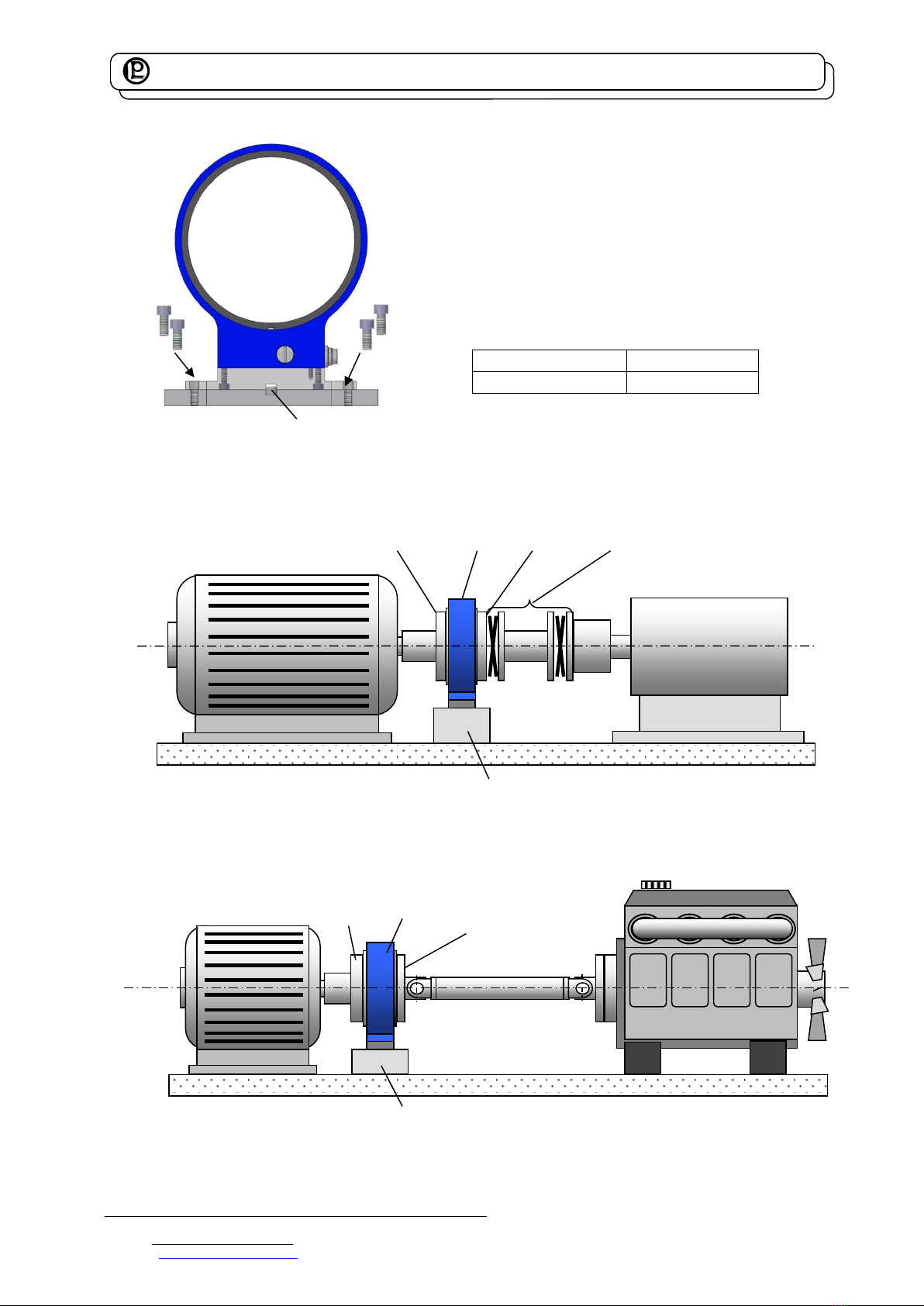
4.3 Basic Assembly.............................................................................................................................. 9
4.3.1 Assembly Example ................................................................................................................. 9
4.3.2 Using Center Bore ................................................................................................................ 10
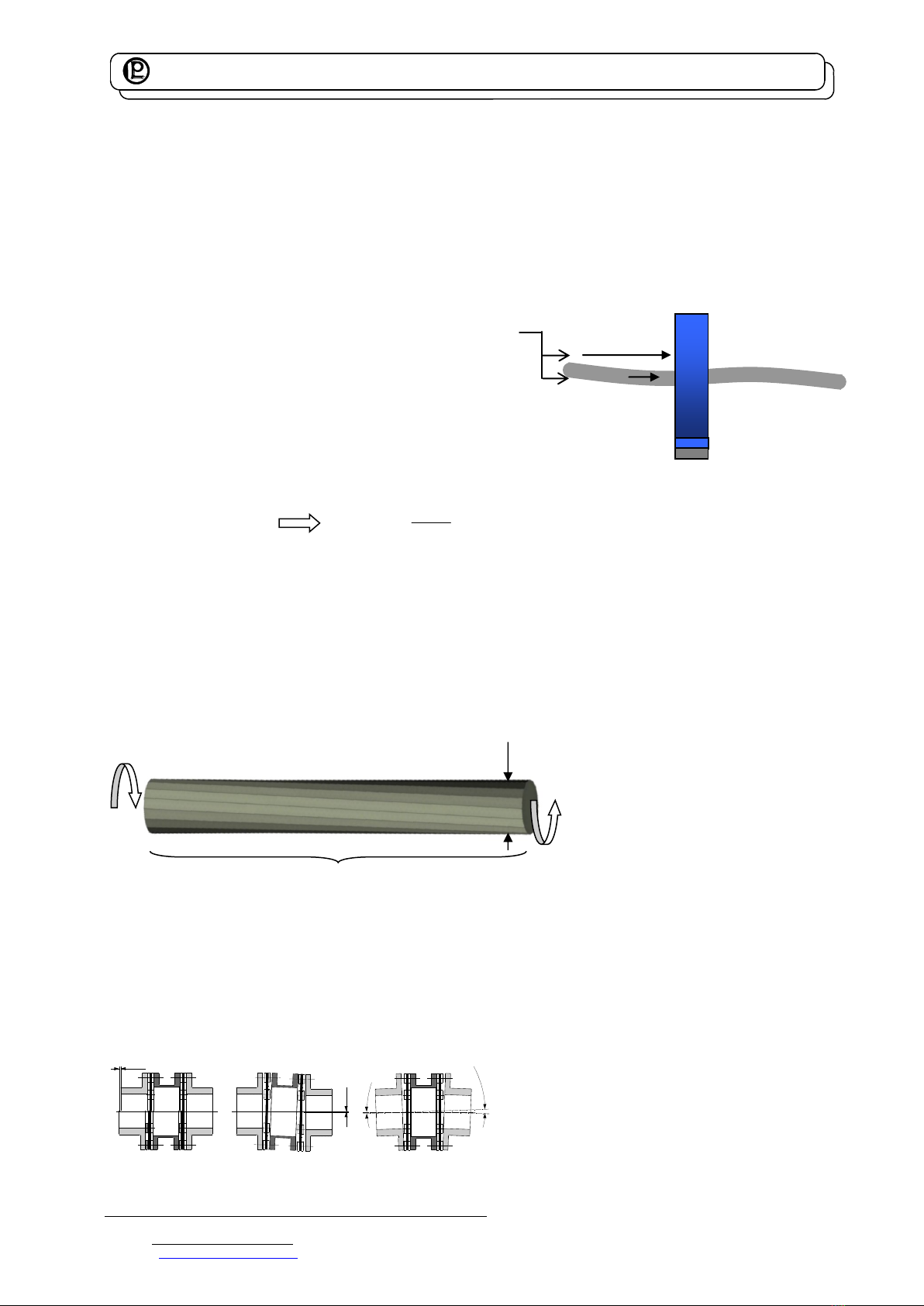
4.4 Couplings ..................................................................................................................................... 10
4.4.1 Alignment of the Measurement Arrangement....................................................................... 11
5Electrical Connection........................................................................................................................... 11
5.1 Pin Connection............................................................................................................................. 11
5.2 Cable............................................................................................................................................ 11
5.3 Shielding Connection ................................................................................................................... 11
5.4 Installation of Measuring Cables.................................................................................................. 11
5.5 Speed Sensor (Option) ................................................................................................................ 12
6Measuring............................................................................................................................................ 12
6.1 Engaging ...................................................................................................................................... 12
6.2 Direction of Torque....................................................................................................................... 12
6.3 Static / Quasi-Static Torques ....................................................................................................... 12
6.4 Dynamic Torques ......................................................................................................................... 12
6.4.1 General ................................................................................................................................. 12
6.4.2 Torsional Natural Resonances ............................................................................................. 12
6.4.3 Bending Natural Resonances ............................................................................................... 13
6.5 Speed Limits ................................................................................................................................ 13
6.5.1 Balancing .............................................................................................................................. 13
6.6 Disturbance Variables .................................................................................................................. 13
7Maintenance........................................................................................................................................ 13
7.1 Rotating Sensors.......................................................................................................................... 13
7.2 Trouble Shooting.......................................................................................................................... 14
8Transportation and Storage ................................................................................................................ 14
8.1 Transportation .............................................................................................................................. 14
8.2 Storage......................................................................................................................................... 14
9Disposal............................................................................................................................................... 15
10 Calibration........................................................................................................................................ 15
10.1 Proprietary Calibration.............................................................................................................. 15
10.2 DKD-Calibration........................................................................................................................ 15
10.3 Re-Calibration........................................................................................................................... 15
11 Data Sheet....................................................................................................................................... 15
12 Literature.......................................................................................................................................... 15

LORENZ MESSTECHNIK GmbH
Obere Schloßstr.131
73553 Alfdorf
07172 / 93730-0
Fax 07172 /93730-22
E-Mail: info@lorenz-sensors.com
Technical changes under reserve
090329a.docx
Internet: www.lorenz-sensors.com
Page 5 of 15
1 Read First
1.1 Safety and Caution Symbols
Caution:
Injury risk for persons
Damage of the device is possible.
Note:
Important points to be considered.
1.2 Intended Use
Lorenz Messtechnik GmbH devices may only be used for measurement tasks and the directly related
control tasks. Any other use is considered improper. The torque sensors are not safety components in the
sense of the intended use. The sensors need to be transported and stored appropriately. The assembly,
commissioning and disassembling must take place professionally.
1.3 Dangers
The torque sensor is fail-safe and corresponds to the state of technology.
1.3.1 Neglecting of Safety Notes
At inappropriate use, residual dangers can emerge (e.g. by untrained personnel). The operation manual
must be read and understood by each person entrusted with the assembly, maintenance, repair,
operation and disassembly of the torque sensor.
1.3.2 Residual Dangers
The plant designer, the supplier, as well as the operator must plan, realize and take responsibility for
safety-related interests for the sensor. Residual dangers must be minimized. Residual dangers of the
torque measurement technique must be pointed out.
Human mistakes must be considered. The construction of the plant must be suitable for the avoidance of
dangers. A danger-analysis for the plant must be carried out.
1.4 Reconstructions and Modifications
Each modification of the sensors without our written approval excludes liability on our part.
1.5 Personnel
The installation, assembly, commissioning, operation and the disassembly must be carried out by
qualified personnel only. The personnel must have the knowledge and make use of the legal regulations
and safety instructions.
.

LORENZ MESSTECHNIK GmbH
Obere Schloßstr.131
73553 Alfdorf
07172 / 93730-0
Fax 07172 /93730-22
E-Mail: info@lorenz-sensors.com
Technical changes under reserve
090329a.docx
Internet: www.lorenz-sensors.com
Page 6 of 15
1.6 Warning Notes
Attention must be paid to the accident prevention regulations of the trade associations.
Coverings and casings are necessary before operating the sensor. This is also valid for
commissioning, maintenance and trouble shooting.
Duties of the coverings and casings are:
Protection from detaching parts
Protection from contusion and shear
Prevention from reaching rotating parts
Prevention from being tangled up and/or getting caught by parts
Coverings may
Not grind
Not rotate
Coverings are also necessary outside of operating and motion travel areas of persons.
These demands can be modified if other sufficient safety devices are available. During
operation, the safety precautions must be operative. Vibrations can cause device
damages.
2 Term Definitions
2.1 Terms
Measuring Side:
Mechanical connection of the torque sensor in which the torque to be measured is applied. Usually, this
side has the smallest moment of inertia.
.
Drive Side:
Mechanical connection of the torque sensor on the opposite side of the measuring side, usually with the
largest moment of inertia.
Low Torque Resistance Side:
The shaft of the arrangement (drive, load) which can be rotated significantly smaller with torque than the
nominal torque of the torque sensor M << Mnenn.
2.2 Definition of the Pictograms on the Torque Sensor
The measuring side of the torque sensor is identified as follows.
Measuring side:
or M
Further indications can be found on the sensor data sheet.
3 Product Description
The sensor measures static and dynamic torques. The mounting position of the torque sensor is
horizontally.
Caution: it must be differentiated between measuring side and drive side, see data sheet of the sensor:
http://www.lorenz-sensors.com
M

LORENZ MESSTECHNIK GmbH
Obere Schloßstr.131
73553 Alfdorf
07172 / 93730-0
Fax 07172 /93730-22
E-Mail: info@lorenz-sensors.com
Technical changes under reserve
090329a.docx
Internet: www.lorenz-sensors.com
Page 7 of 15
3.1 Mechanical Setup
The sensor consists of a stationary part, the stator and a rotary part, the rotor.
3.2 Electrical Setup
The electronics integrated in the sensor consistsof two parts.
The first part is in the stator and has following tasks:
Stabilization of the supply voltage
Electric supply of the rotor electronics through the rotating transformer
Preparation of the measurement signal from the rotor
Transmission of the torque measurement signal to the cable connection
The second part of the electronics is placed in the rotor of the torque sensor
with following functions:
Supply of the SG full bridge with DC voltage
Preparation of the electrical torque measurement signal
Transmission of the measurement signal to the stator
Stator Electronics
supply and measuring
amplifier
Rotor Electronics
supply of the SG full
bridge and the
measuring amplifier
Stator
Rotating Transformer
signal transmission from stator
to rotor and reversed
Meas. Body
with SG bridge
Cable Connection
electrical connection
Air Gap
for free rotation of
the rotor
Mounting Plate
for fastening of the stator
Slot Hole Drillings 2 x M8
for fastening
Keyway
for stator alignment

LORENZ MESSTECHNIK GmbH
Obere Schloßstr.131
73553 Alfdorf
07172 / 93730-0
Fax 07172 /93730-22
E-Mail: info@lorenz-sensors.com
Technical changes under reserve
090329a.docx
Internet: www.lorenz-sensors.com
Page 8 of 15
4 Mechanical Assembly
4.1 Rotor Assembly
Caution: During the assembly inadmissibly large forces may not act on the sensor or the
couplings. Connect the sensor electrically during the assembly and observe the signal, the
measurement signal may not exceed the limit values.
To avoid falling down, the sensor must be supported during the assembly.
Admissible assembly offset from rotor to stator: 4.2 Stator Assembly
The sensor is installed into the shaft string through flanges. Prior to the assembly, flanges must be
cleaned with solvent (e.g. acetone), they must be free of foreign particles. The surface of the flange must
have an evenness of minimum 0,02 mm.
For transportation and easier assembly, the torque sensor is delivered with fixing plates.
The optimal axial position of Stator to Rotor is defined by fixing plates.
(per plate 3 screws M4x10)
Mounted Fixing Plates
Removed Fixing Plates
Without Fixing Plates
Tighten screws evenly on the flanges. Torque transmission by surface pressure, only. The installation and
alignment of the torque sensor occurs with mounted fixing plates.
Use appropriate tightening torques for the screws of strength 10.9 with suitable length. The screws
should be secured with screw locks (e.g. LOCTITE No. 242).
Nominal Torque
Screw
Quantity
Thread depth
Tightening torque
50 / 100 N·m
M 6
8
12 mm
14 N·m
200 N·m
M 8
8
12 mm
35 N·m
500 / 1000 N·m
M12
8
12 mm
120 N·m
2000 N·m
M14
8
17 mm
190 N·m
5000 N·m
M18
8
17 mm
490 N·m
Caution!
At alternating torque, the flange connection screws must absolutely be secured with
screw locks. Otherwise the connection screws may loosen.
The used screws may not be too long:
Shunt of the torque measurement
Flange connection is not twist-protected
Then remove the 3 fixing plates and control the position of shaft to stator:
a) Axial alignment of the shaft
b) Evenness of the air gap (shaft may not grind at the stator)

LORENZ MESSTECHNIK GmbH
Obere Schloßstr.131
73553 Alfdorf
07172 / 93730-0
Fax 07172 /93730-22
E-Mail: info@lorenz-sensors.com
Technical changes under reserve
090329a.docx
Internet: www.lorenz-sensors.com
Page 9 of 15
4.2 Stator Assembly
Use keyway for the axial alignment
Align stator to shaft
Rotor may not touch the stator
Note the axial position of rotor to stator
Tolerance: ± 0,5 mm
Tighten screws with a torque wrench.
Use suitable washers, if necessary.
Strength:
8.8
Tightening torque:
24 N·m
4.3 Basic Assembly
4.3.1 Assembly Example
To keep shear forces and axial forces to a minimum, shiftable couplings must be used. See chapter
couplings in this manual.
Example combustion engine with joint shaft
Angular displacements result in additional forces on the torque sensor. See data of the manufacturer of
the joint shafts.
DR-2800 Flange Coupling
Specimen
Load machine
Mounting surface
Fixing plate
2x M8
2x M8
Load machine
DR-2800
Combustion engine
Mounting
surface
Fixing plate
Joint shaft
Flange
Keyway
Flange
Flange

LORENZ MESSTECHNIK GmbH
Obere Schloßstr.131
73553 Alfdorf
07172 / 93730-0
Fax 07172 /93730-22
E-Mail: info@lorenz-sensors.com
Technical changes under reserve
090329a.docx
Internet: www.lorenz-sensors.com
Page 10 of 15
Hose
Sensor
ges
M
S
M
t
M
4.3.2 Using Center Bore
Each part, led through the sensor, means a torque shunt.
By this, a torque portion will bypass the sensor.
This portion is not measured →so the shunt must be small in relation to the measured torque.
The large center bore is suitable for the lead-through of
hydraulic hoses
pneumatic hoses
rods
Note:
The lead-through part may not acquire
torque which will influence the measurement
result
Applied torque
Ms
for twisting of the led-
through parts must be very small against the
measured torque
Mt
.
Note at this arrangement:
Stges MMM
St MM
e.g.
tS MM 2000
1
Otherwise, a disturbance of the measuring signal will be the result from the torque shunt.
Example for a round shaft:
Twist angle of the torque sensor:
Twist angle of the lead-through part:
M
= Torque;
l
= Length of the torsion part;
d
= Diameter of the torsion part
Both twist angles must be the same.
This means: in order to achieve as small as possible torque resulting from the lead-through part it must
have a small diameter (cross-section)
be long
4.4 Couplings
Couplings must be able to balance an axial, radial or angular offset of the shafts and not allow large
forces to act on the sensor.
Axial offset Radial offset Angular offset
ΔKa
Δ
K
w
2
x
Δ
K
w
ΔKr
Torque
M
Body
M
l
d

LORENZ MESSTECHNIK GmbH
Obere Schloßstr.131
73553 Alfdorf
07172 / 93730-0
Fax 07172 /93730-22
E-Mail: info@lorenz-sensors.com
Technical changes under reserve
090329a.docx
Internet: www.lorenz-sensors.com
Page 11 of 15
If shear forces and axial forces act on the torque sensors, they can cause zero point shifts, which falsify
the measuring signal as a disturbance variable during the measurement.
4.4.1 Alignment of the Measurement Arrangement
Precisely alignment of the couplings reduces the reaction forces and increases the durability of the
couplings and the shaft bearing.
Frequently, an alignment of the couplings with a straight edge in two levels, vertical to each other, is
sufficient.
At high speed, however, an alignment of the coupling (shaft ends) with a dial indicator or a laser is
recommended.
Further points to be considered
The axis height of the torque sensor (data sheet) must be considered.
An air gap between rotor and stator must be available. The rotor may not touch the stator in any
operating condition.
Axial position of the rotor to the stator: see data sheet.
For further references see coupling manual and limit thrust load and shear load of the torque
sensor (data sheet).
5 Electrical Connection
5.1 Pin Connection
See test certificate, as well.
12-
pin
Analog Output
View: socket on soldering side
Pin A
NC
Pin B
NC
Pin C
Signal
±5 V / (±10 V)
Pin D
Signal GND
0 V
Pin E
Excitation GND
0 V
Pin F
Excitation +
12 ... 28 VDC
Pin G
Option Speed
TTL
Pin H
NC
Pin J
NC
Pin K
NC
Pin L
NC
Pin M
Housing
5.2 Cable
Only use a shielded cable with minimum capacity. We recommend measuring cables from our product
range. They have been tested in combination with our sensors and meet the metrological requirements.
5.3 Shielding Connection
In combination with the sensor and the external electronics, the shield forms a Faraday Cage. By this,
electro-magnetic disturbances do not have any influence on the measurement signal.
5.4 Installation of Measuring Cables
Do not lay measuring cables together with control lines or power cables. Always assure that a large
distance is kept to engines, transformers and contactors, because their stray fields can lead to
interferences of the measuring signals.
If troubles occur through the measuring cable, we recommend to lay the cable in a grounded steel
conduit.
.

LORENZ MESSTECHNIK GmbH
Obere Schloßstr.131
73553 Alfdorf
07172 / 93730-0
Fax 07172 /93730-22
E-Mail: info@lorenz-sensors.com
Technical changes under reserve
090329a.docx
Internet: www.lorenz-sensors.com
Page 12 of 15
5.5 Speed Sensor (Option)
A hall sensor is located between the pulse wheel and the permanent magnet. If a tooth of the pulse wheel
passes the energized hall sensor, the field intensity of the permanent magnet changes. By this, hall
voltage occurs which is processed to a rectangular signal by the integrated evaluation electronics.
6 Measuring
6.1 Engaging
The warming-up period of the torque sensor is approx. 5 min. Afterwards the measurement can be
started.
The warming-up period of the torque sensor is approx. 5 min.
6.2 Direction of Torque
Torque means clockwise torque if the torque acts clockwise when facing the shaft end. In this case a
positive electrical signal is obtained at the output.
Torque sensors by Lorenz Messtechnik GmbH can measure both, in clockwise and counter-clockwise
direction.
6.3 Static / Quasi-Static Torques
Static and/or quasi-static torque is a slowly changing torque.
The calibration of the sensors occurs statically on a calibration device.
The applied torque can accept any value up to the nominal torque.
6.4 Dynamic Torques
6.4.1 General
The static calibration procedure of torque sensors is also valid for dynamic applications.
Note: The frequency of torques must be smaller than the natural frequency of the mechanical
measurement setup.
The band width of alternating torque must be limited to 70 % of the nominal torque.
6.4.2 Torsional Natural Resonances
Estimation of the mechanical natural frequencies:
21
0
11
2
1
JJ
cf
f0
J1, J2
c
= Natural Frequency in Hz
= Moment of Inertia in kg*m²
= Torsional Rigidity in Nm/rad
Further methods for the calculation of natural resonances are corresponding purchasable programs or
books (e.g. Holzer-Procedure (Dubbel, Taschenbuch für den Maschinenbau, Springer Verlag) or
equivalent commercially available programs.
Operation of the device in natural resonance can lead to permanent damages.
c
Pulse wheel
(ferromagnetic)
N
S
Permanent magnet
Hall-probe
Output signal
J1
J2

LORENZ MESSTECHNIK GmbH
Obere Schloßstr.131
73553 Alfdorf
07172 / 93730-0
Fax 07172 /93730-22
E-Mail: info@lorenz-sensors.com
Technical changes under reserve
090329a.docx
Internet: www.lorenz-sensors.com
Page 13 of 15
6.4.3 Bending Natural Resonances
Together with the shaft and the couplings, the sensor forms a bending vibration.
Bending vibrations are stimulated by unbalance. balance well
Do not operate the system in bending natural resonance.
Apply bursting protection around the shaft string.
6.5 Speed Limits
The maximum speed indicated in the data sheet may not be exceeded in any operating state.
6.5.1 Balancing
The sensor is balanced (for balancing quality see datasheet). At high speeds, it is recommended to
perform one operational balancing.
Balancing bores may not be applied out on the sensor!
6.6 Disturbance Variables
Measured value falsifications can occur by
Vibrations,
Temperature gradients,
Temperature changes,
Emerging disturbance variables during operation, e.g. imbalance,
Electrical disturbances,
Magnetic disturbances,
EMC (electromagnetic disturbances),
Therefore avoid these disturbance variables by decoupling of vibrations, covers, etc.
7 Maintenance
Maintenance schedule
Action
Frequency
Date
Date
Date
Control of cables and connectors
1x p.a.
Calibration
< 26 months
Control of fixation (flanges, shafts)
1x p.a.
7.1 Rotating Sensors
This sensor type is largely maintenance free.
Operation of the device in bending natural resonance can lead to permanent damages .
This applies for bending natural
resonance:
E = Elasticity modulus of material
d = Shaft diameter
m = Mass
= Angular frequency
f = Natural frequency in Hz
Preferably stable design
Diameter (d )
Length lpreferably short
Mounting
Shaft
Sensor with coupling
m
l
m

LORENZ MESSTECHNIK GmbH
Obere Schloßstr.131
73553 Alfdorf
07172 / 93730-0
Fax 07172 /93730-22
E-Mail: info@lorenz-sensors.com
Technical changes under reserve
090329a.docx
Internet: www.lorenz-sensors.com
Page 14 of 15
7.2 Trouble Shooting
This table is used to find the most common errors and debugging.
Problem
Possible Cause
Debugging
No signal
No sensor excitation
Outside of permissible range
Connect excitation
Cable defect
No mains supply
Signal output connected wrong
Connect output correctly
Evaluation electronics defect
Sensor does not react to torque
Shaft not clamped
Clamp correctly
No power supply
Outside of permissible range
Connect supply
Cable defect
No mains supply
Cable defect
Repair cable
Connector connected wrong
Connect correctly
Signal has dropouts
Axial position rotor to stator
outside of tolerance
Align rotor
Cable defect
Repair cable
Zero point outside of tolerance
Cable defect
Repair cable
Shaft mounted distorted
Mount correctly
Distorted shaft string
Release distortion
Strong lateral forces
Reduce lateral forces
Distorted flanges
Check evenness of flange-
surfaces
Shaft overloaded
Send to manufacturer
Wrong torque indication
Calibration not correct
Re-calibrate
Sensor defect
Repair by manufacturer
Torque shunt
Eliminate shunt
Shaft grinds
Shaft grinds in the rotor
Align shaft
Concentricity of the parts is not
ensured
Lateral forces too large
Decrease lateral forces
Oscillations
Alignment of shaft not correct
Align correctly
Unbalance
Balance the corresponding parts
8 Decommissioning
All sensors must be dismantled professionally. Couplings may not be damaged. Do not strike sensor
housings with tools. Do not exert punches on the sensor with a tool. Do not apply bending moments on
the sensor, e.g. through levers. The torque sensor must be supported to avoid falling down during the
dismantling.
9 Transportation and Storage
The transportation of the sensors must occur in suitable packing. The sensor should be wrapped in foil,
so no packing material can get into the device. Larger sensors should be packed in boxes. Use the
supplied fixing plates for storage or transportation of the sensor.
9.1 Transportation
Only release well packed sensors for transportation. The sensor should not be able to reciprocate in the
packing. The sensor must be protected from moisture.
Use only suitable means of transportation.
9.2 Storage
The storage of the sensors must occur in dry, dust-free rooms, only.
Lightly oil shafts and flanges before storing (rust).

LORENZ MESSTECHNIK GmbH
Obere Schloßstr.131
73553 Alfdorf
07172 / 93730-0
Fax 07172 /93730-22
E-Mail: info@lorenz-sensors.com
Technical changes under reserve
090329a.docx
Internet: www.lorenz-sensors.com
Page 15 of 15
10 Disposal
The torque sensors must be disposed in accordance with applicable legislation.
For this, see our “General Terms and Conditions” www.lorenz-sensors.com
11 Calibration
At the time of delivery, torque sensors have been adjusted and tested with traceable calibrated measuring
equipment at factory side. Optionally, a calibration of the sensors can be carried out.
11.1 Proprietary Calibration
Acquisition of measurement points and issue of a calibration protocol Traceable calibrated measuring
equipment is being used for the calibration. The sensor data are being checked during this calibration.
11.2 DKD-Calibration
The calibration of the sensor is carried out according to the guidelines of the DKD and/or DAkkS.. The
surveillance of the calibrating-laboratory takes place by the DAkkS. At this calibration, the uncertainty of
measurement of the torque measuring instrument is determined. Further information can be obtained
from Lorenz Messtechnik GmbH.
11.3 Re-Calibration
The recalibration of the torque sensor should be carried out after 26 months at the latest.
Shorter intervals are appropriate:
Overload of the sensor
After repair
After inappropriate handling
Demand of high-quality standards
Special traceability requirements
12 Data Sheet
See www.lorenz-sensors.com
13 Literature
Dubbel, Taschenbuch für den Maschinenbau, Springer Verlag.
Table of contents
Other LORENZ MESSTECHNIK Accessories manuals