Lortone LU6X-130 Datasheet

LORTONE, inc • 12130 Cyrus Way, Mukilteo, WA 98275 • Phone: 425-493-1600
3/08 Page 1
Copyright © 2008 Lortone, Inc
LU6X-130
Instructions and Parts List
(including LU6X Basic)
Operating Instructions
Introduction
The LU6X is one the most versatile pieces of equipment available to the lapidary enthusiast.
It combines sawing, grinding, and polishing operations in one machine. Please read the
following specications and directions prior to using your Model LU6X.
Set-Up
Unpack the machine and check for shipping damage. If damage is found, you must notify the
carrier immediately and le a claim.
The LU6X should be mounted to a solid workbench with four 1/4” bolts or wood screws through
holes provided.
Motor Mounting
The motor is installed on the clip-on motor mount which slides directly onto the machine. A
2-1/2” motor pulley is supplied for proper shaft speed. We recommend a 1/3hp, 1725 rpm motor
(LORTONE # 300-022). A motor of at least 1/4hp is required for adequate operation.
The Model LU6X-130 comes with motor.
Install the motor on the motor mount using the bolts provided and tighten the bolts nger tight.
Slide the motor mount into place on the mounting clip on the back of the machine. Position the
motor so that the drive belt is just tight enough to eliminate belt slippage - an overly tight belt
can cause excessive bearing wear, noise or vibration. Motor rotation should be clockwise to drive
the shaft (show on next page, Fig. 1).
LU6X-130 Item # 061-092
LU6X Basic Item # 061-090
LORTONE

LORTONE, inc • 12130 Cyrus Way, Mukilteo, WA 98275 • Phone: 425-493-1600
3/08 Page 2
Copyright © 2008 Lortone, Inc
Blade Installation
A 6” diameter diamond blade with a 1/2” arbor hole is required.
Remove trim table from unit (see parts list drawings). Remove the
arbor shaft nut by turning it CLOCKWISE and remove the outer blade
ange from shaft. Slide the blade onto the shaft. If the blade comes
with an adapter bushing, be careful the correct bushing remains in
place during installation. Re-install the outer shaft ange and
replace the arbor shaft nut. Tighten the arbor shaft nut by turning
it COUNTER-CLOCKWISE. DO NOT OVERTIGHTEN the arbor shaft nut
as this can distort the shaft anges. Reinstall trim table.
Slight blade wobble is normal with thin lapidary blades. Loosening
the arbor shaft nut and rotating the blade slightly will often reduce
wobble.
Vise Attachment Installation
Vise attachment should be installed on trim table with self tapping
sheet metal bolts in holes provided as shown on the parts list
drawing. Care should be taken to assure that the vise runs parallel
to the blade. Alignment can be checked by clamping a pencil in the
vise with the point lightly against the side of the blade at the front.
Slide the vise with pencil to the rear of the blade – The pencil point
should lightly touch the side of the blade as the vise is moved
towards the back. (Fig.2). If the pencil point pulls away from the
blade or digs into the blade, loosen the vise mounting screws and
adjust the vise until the alignment is good.
Grinding Wheel & Sanding Drum Installation
The LU6X-130 machine has enough space on the right side to use
one grinding wheel, a sanding drum and a screw-on polish head
(items included with LU6X-130; not included with Basic LU6X). If
using a grinding wheel or sanding drum with a different inside
diameter, make sure to use bushings of the correct size. Check
with the manufacturer of the wheels for the correct bushing.
The grinding wheel is installed on the section of shaft that is ¾” in
diameter. Install the ¾” ID plated ange onto the shaft and slide it
up against the retaining ring. Install the 6” x 1” grinding wheel onto
the shaft using the correct plastic bushing. Install the second ¾” ID
ange onto the shaft. Install and tighten the ¾” Hex Nut against the
second ange. (Fig.3)
The sanding drum is installed on the section of the shaft that is ½”
in diameter. Install one ½” ID plated ange onto the shaft and slide
it up against the step on the shaft. Install the 6” x 2-1/2” sanding
drum onto the shaft. Install the second ½” ID ange onto the shaft.
Install and tighten the ½” Hex Nut against the second ange. (Fig.4)
Keeper Collar
Nut
Collar
Grinding Wheel or
felt Wheel
Mark
Pencil
Slide
Vise
Fig. 3
Fig. 2
Shaft
Collars
Nut
Spacer
Sanding Drum
Rotation
Fig. 1
Fig. 4

LORTONE, inc • 12130 Cyrus Way, Mukilteo, WA 98275 • Phone: 425-493-1600
3/08 Page 3
Copyright © 2008 Lortone, Inc
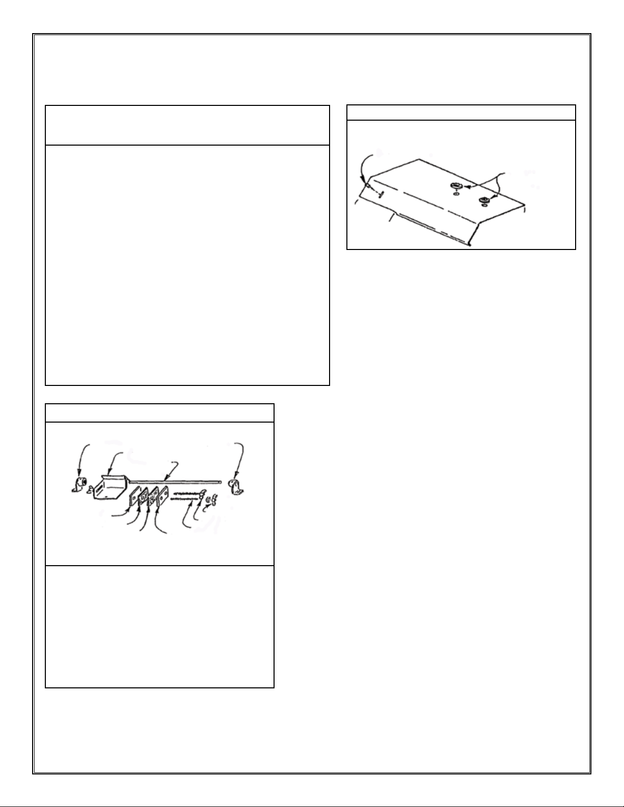
Polishing Head Installation
The LU6X-130 machine comes with a felt-faced polish head. Insert
the ¼-20 threaded end of the polish head into the end of the shaft
and tighten by turning the polish head clockwise. Avoid contaminating
the polish head during installation.
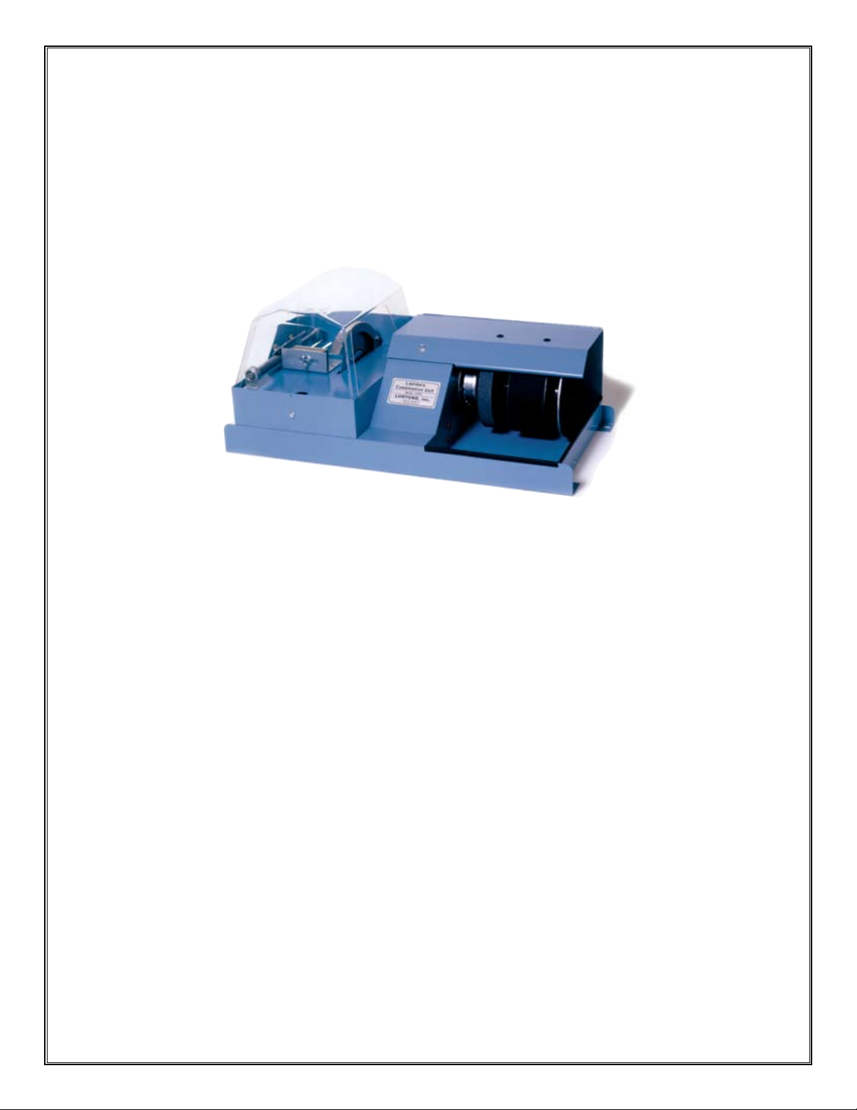
For versatility, additional polish heads can be purchased either with or
without the felt. Leather discs can be attached to the rubber face
polish-heads with feathering disc cement. If these heads are used for
sanding and are threaded 1/2” N.F.R.H., they may be installed on shaft
as show in Fig. 5. If they are used with a polishing pad, it is
recommended they be installed on the shaft by themselves (see Fig. 6)
to eliminate possibility of contamination.
Sawing
Pour coolant into saw case until 1/4” of blade is emerged in coolant
(see Fig. 7). We recommend using water with a rust preventative or
quality oil formulated for lapidary use. CAUTION: DO NOT use
Kerosene, Motor Oil, Transformer Oil, or Automobile Antifreeze.
Feed material into the blade with even pressure. Never force the
material into the diamond blade. The rate of feed should never be so
great that the blade slows down. For difcult to handle shapes, clamp
the material in the vise.
Grinding
It is important to remember that the saw is still running while the LU6X
is being used for grinding, sanding or polishing. To reduce coolant mist
from the saw when using the grinding side of the machine, place a
small household sponge on the trim table directly in front of the blade.
When you are ready to use the saw, remove the sponge.
The LU6X is designed to be operated with either a water drip system or
a recalculating system.
Water
Grinding Wheel
Sponge
Polishing Head
Shaft
Fig. 7
Fig. 6
Make sure 1/4” of
blade is submerged
in coolant
Shaft
Collars
Polishing
Head
Sanding
Drum
Spacer
Fig. 5
Periodic Maintenance
The bearings used in this arbor are sealed and lubricated for life. The nuts and collars are plated to
resist corrosion. The shaft is stainless steel which will also resist corrosion.
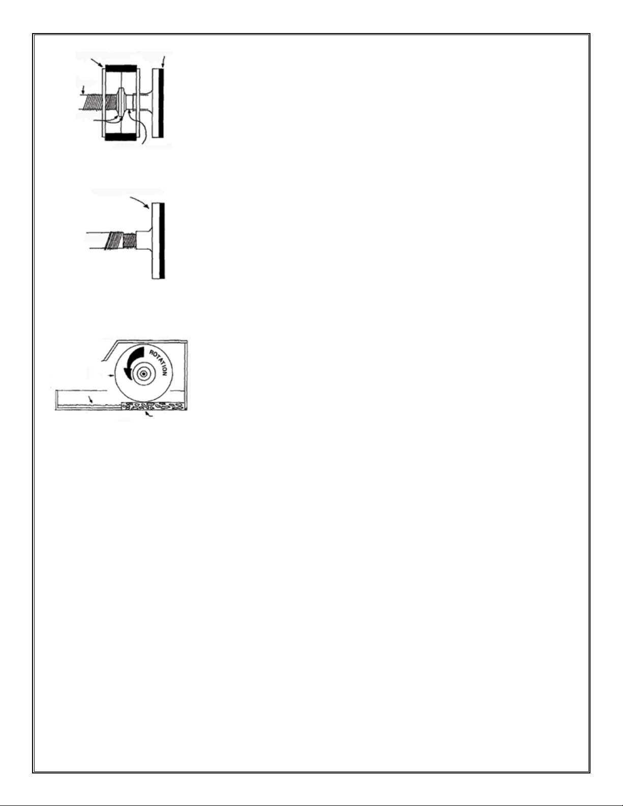
Helpful Hints
If it is inconvenient to hook up water valve and drain on grinding wheel side of unit, an acceptable
option can be to place a small amount of water in pan and carry it to the grinding wheel with the use
of a house hold sponge (see Fig.8).
The LU6X-130 is supplied with a 2-1/2” pulley & V-belt. A precision turned, ground, and polished shaft
is mated with sealed for life ball bearings for smooth, quiet operation. The point to remember is that
the basic machine is a smooth running unit. Vibrations and noise, which can occur during operation
of your machine, can often be traced back to the items being installed on the arbor shaft (grinding
wheels, sanding drums, polishing heads, etc.) not being trued and balanced.

LORTONE, inc • 12130 Cyrus Way, Mukilteo, WA 98275 • Phone: 425-493-1600
3/08 Page 4
Copyright © 2008 Lortone, Inc
Qty Part # Description
1 060-101 Trim Table
1 061-001 Arbor Shaft
1 061-100 Frame
2 063-008 Bearing Cover
2 240-069 *Bearing Isolator (not shown)
2 200-006 Ball Bearing
1 206-023 Retaining Ring
1 210-030 Drive Belt
1 211-015 2-1/2” x 3/4” Pulley
1 216-001 Drain Plug
2 320-006 Rubber Grommet
1 290-015 Thumb Screw
1 481-044 1/2”-20 LH Hex Nuts
1 481-024 1/2”-20 RH Hex Nuts
1 481-026 3/4”-16 RH Hex Nuts
2 101-001 1-1/2” x 1/2” Flange
1 060-002 Blade Guard
1 485-037 1-3/8” #10 Machine Screw
1 481-027 10/32 Hex Nut
1 489-062 #8 SAE Washer
1 300-022 1/3 hp Motor w/Switch & Cord**
** Items not included with LU6X Basic
Qty Part # Description
1 074-092 Hood**
1 522-039 6” x .025 x 1/2 Standard Blade
1 035-102 Motor Mount
4 209-003 Small Bump-on Foot
4 480-002 1/4” x 3/4” Carriage Bolt (not shown)
4 481-028 1/4” Hex Nut (not shown)
4 489-012 1/4” Flat Washer (not shown)
1 057-002 Splash Shield
1 481-021 6-32 Hex nut (not shown)
1 485-005 6-32 x 3/8” Round Head Machine Screw
1 489-066 #6 SAE Washer (not shown)
1 035-104 Belt Guard
4 209-001 Large Rubber Foot
1 209-010 Rubber Plug
1 211-013 2-1/2” x 1/2” Pulley (for motor)
2 101-023 3” x 3/4” Flange
2 101-011 2” x 1/2” Flange
1 488-032 10-24 x 1/2” Hex Head Threaded
Cutting Screw (not shown)
060-002
074-092
071-091
035-104
210-030
211-013
300-022
035-102
209-001
216-001
481-044
101-001 200-006*
200-006
211-015
063-008 063-008
206-023
101-011
481-024
216-003
*Not shown 240-069
LU6X-130 Item # 061-092
LU6X Basic Item # 061-090
LU6X-130 Parts List
(including LU6X Basic)
101-023
061-101
061-001
061-100
481-026

LORTONE, inc • 12130 Cyrus Way, Mukilteo, WA 98275 • Phone: 425-493-1600
3/08 Page 5
Copyright © 2008 Lortone, Inc
Accessory Kit including:
Qty Part # Description
1 025-060 6” x 1/2” RH Spin-on Polish Head**
1 508-001 6” Felt Disc (attached to polish head)
1 072-090 EX625 X 1/2” Drum w/400 grit belt**
1 500-072 6” x 1” 100 Black Grinding Wheel**
1 511-001 TB4 Plastic Bushing (in grinding wheel)**
1 071-091 LU6X Vise**
1 501-012 2-1/2” x 18-15/16” 220 Grit Belt**
1 501-015 2-1/2” x 18-15/16” 600 Grit Belt**
1 549-010 Lortone Templates (5pk)**
4 550-010 5/16” Wood Dop Stick**
1 588-010 1/8 lb Dop Wax (1/2 stick)**
1 591-044 1 oz Cerium Oxide**
1 120-001 Aluminum Scribe**
1 120-002 Brass Scribe**
**Not included with LU6X Basic
Part # Description
071-001 1-Hole Vise Plate
071-002 2-Hole Vise Plate
071-003 2-Hole Vise Pad
071-004 Vise Bolt
071-005 1-Hole Vise Pad
071-006 Guide Shaft
071-100 Vise Bolt w/Wing Nut
071-101 Vise Carriage
071-102 Vise Guide Support
481-079 Wing nut
071-091 Model LU6V Vise Assembly**
071-102 071-101
071-006
071-102
481-079
071-100
071-004
071-002
071-003
071-005
071-001
Water Supply System
488-051
320-006
Insert 1/4” plastic tubing
through grommets to supply
water to wheels
LU6X-130 Parts List
(continued)
This manual suits for next models
3
Table of contents
Other Lortone Lathe manuals