manuals.online logo
Brands
  1. Home
  2. •
  3. Brands
  4. •
  5. SOMFY
  6. •
  7. Receiver
  8. •
  9. SOMFY Axroll User manual

SOMFY Axroll User manual

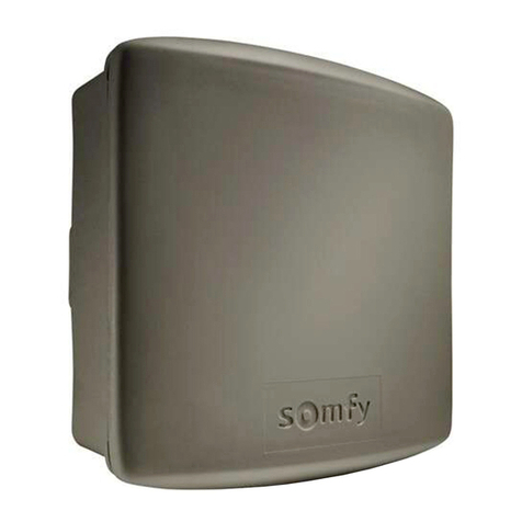
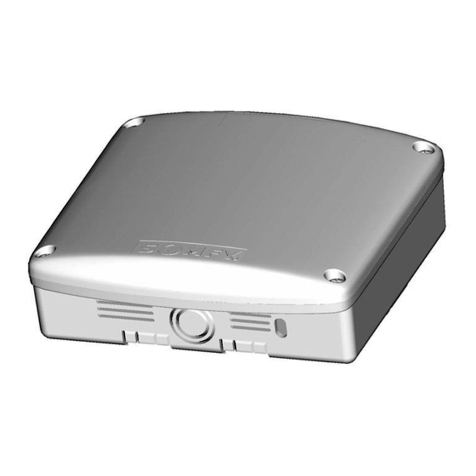
Radio receiver for rolling garage door
Installation Manual
Power supply voltage : 230Vac 50-60 Hz.
Fuse : 250V 5A with timeout
Max motor power : 230Vac 750W.
Protection rating : IP 55.
Ambient operating T° : -15°C to +55°C.
Radio frequency : 433.42MHz
Accessory power supply : 24Vcc (direct).
Resistance values for resistive sensor
bar : From 4 to 12KΩ
Maximum current for accessories : 0.33A i.e. 8W max.
(cells, keypads, loops, sensor bar, etc…) or 13W intermittent (orange light
10W + accessories 3W.)
Orange light : 24V, 10W max or 230V 40W max
Area lighting : 230Vac, 500W.
Auxiliary output : Contact NO, 250Vac 500W.
Operating class : 1, the ground must be connected.
Number of maximum channels : 32
150 mm
150 mm
40 mm
=: Automatic mode
Pressing the remote control opens and closes automatically
after timeout T1 (chapter 3.8).
During closing, pressing the remote control again or the
detection of an obstacle reopens the door.
=: Semi-automatic mode
Pressing the control triggers opening or closing. Pressing again
during opening has no effect.
Pressing during closing reopens the door.
=: Sequence mode (default mode)
Cyclic operation (up / stop / down / stop...).
Pressing during opening or closing stops
without reversion.
=: Sequential mode + Timeout
Similar to the sequential mode, but with automatic closing
after timeout T1 (chapter 3.8).
=: 3-button mode
This mode is used to set a separate control
for opening, closing, and stopping the
door.
=: Forced mode with + & - keys on
the keyboard
This mode is used to control the door using the “ + ” and
“ - ” keys on the Axroll box in the endstop adjustment phase.
Press and hold “ + ” to open.
Press and hold “ - ” to close.
GB
3.1 Configuring the operating mode: parameter (PLANT VALUE = 02)
The AXROLL receiver is used to control a rolling garage door fitted with
a 230V motor with mechanical built-in endstops using KeytisNS 2/4 RTS,
Telis 1/4 RTS, and radio wall switch.
Different safety and signaling systems can be connected to the AXROLL
(resistive, OSE Fraba type or ultrasonic safety edge, photocells, flashlights,
area lighting).
Hereby, SOMFY, declares that this product (AXROLL) is in compliance with the
essential requirements and other relevant provisions of Directive 1999/5/EC.
A Declaration of Conformity is available at the web address www.somfy.com/CE.
Usable in EU,
Ref. N1841034E V1
SOMFY SAS, capital 20 000 000 Euros, RCS Bonneville 303 970 230

in this mode, the safety devices are deactivated
Mandatory installation of safety accessories Mandatory installation of safety accessories
lighting or
signaling
chapter 3.7
Keyswitch
Radio
Wall
Switch
sensor bar
photocells
MAINS
230V - 50Hz
Certain operating modes impose connecting safety accessories (european standards EN 12453). Non compliance with these rules can lead to a facility
hazardousfor its users.
The Axroll has six operating modes:
Configuration
Use the “ +“ or “ -“ keys to change the value of the
parameter.
The last value is recorded automatically (the display is
fixed when pressing the keys).

1 sec.
Use the “ “ or “ “ keyrs to
browse the menu and display
the parameter required.
One second after releasing the key,
the screen indicates the parameter
value to change.
(display blinks)
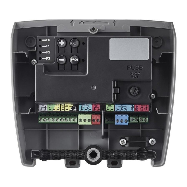
The Axroll control box is fully and easily configured to achieve optimum operation matching the types of accessories connected, as
well as the operation mode required by the user.
The various parameters proposed are not mandatory, and browsing the menus imposes no particular sequence.
Powering on the product: the display indicates the value
Check the motor’s rotation direction using the “ +“ and “ -“ keys.
press and hold the “ +“ key to open the door.
press and hold down the “ -“ key to close the door.
If the operation is reversed, power off the product, and revert the motor’s wiring
(terminals 7 and 9).
Refer to the motor's installation manual to set the end stop system.
CH
AxrollNS
12 1234 5
24V
ac/dc
24V
ac/dc
0V 0V C NC NO
Ground
Phase
Neutral
Motor
Safety
Break
White
(pin -)
Brown
(pin +)
Green
(pin SEC)
OSE SAFETY EDGE
(FRABA)
(
cf. P5 parameter)
Photocells. Ref: 9012763
Keyswitch
Sensor
bar
Ampli
Test
Supply
Contact
230V - 50Hz
Lighting configuration
Ground
Phase
Neutral
lighting
500W max.
Orange light configuration
orange lights.
switch off the mains before any
intervention.
use flexible cables.
connect the ground cables.
after installation, no traction must be
applied to the terminal strips.
Apply the electric installation stan-
dards, as well as the following points:
3
Wiring
1
Checking the motor’s rotation direction
2


Motor ( +safety break)
Measure the motor operating time using permanent running (e.g. 20sec. for rising), then set the T0 parameter (motor operating time,
chapter 3.8) with a value slightly above the time observed (about +3 sec.).
This product complies with the standard EN 60335-2-95.
When installed as recommended in this instruction manual and in accordance with regulations in
force, Axroll allows the installation to comply with EN 13241 and EN 12453 standards. Axroll must
be installed inside the garage with a motor equipped by a manual override system.
To return to the menu, press the “ “ or “ “ keys to return to value C1 (or any other value indicating the pro-
duct’s operation: see § 4) or after a one-minute waiting time.
1
2
3
Pull the antenna wire
through the right-hand
wire grommet.
cf. PA parameter
or
NB: If you want to check the motor's rotation direction, you have to set the parameter =(chapter 3.1)
When using a resistive sensor bar, the latter must be wired onto safety input 1.
The opening safety device stops then recloses partially (non configurable action). The safety action at opening (P1, P2, or P3 = 01) is not configurable (stopage followed with partial door reopening).
However, safety actions upon closing (P1, P2, or P3 = 02) can be configured:
=Stop the door.
=STOP, THEN TOTAL REOPENING OF THE DOOR
=Stop then partial reopening of the door (2 seconds operation)
The self-test function is used to check proper operation of the safety accessories automatically at the
end of closing.
CYCLE COUNTERS
EVENT CODES
Axroll waiting for a command
Opening door
Wait before closing the door
Closing door
Open cell hidden
Close cell hidden
ADMAP cell hidden
Door movement forced by keypad
Emergency stop triggered
Self-testing safety
Permanent contact on “START” input
Wait before motor reversion
FAULT CODES
Safety fault at opening (contact always open)
Safety fault at closing (contact always open)
ADMAP safety fault (contact always open)
Self-test failed on safety input 1
Self-test failed on safety input 2
Self-test failed on safety input 3
Intensity exceeded on 24V power supply (too many accessories connected)
Operating time “T0” too short or motor endstop not reached
For the fault codes from to :
Once the fault is corrected, it is not required to clear the fault code of the
log to return to normal operation.
For defect codes from to :
Once the fault is corrected, you must clear the defect code for
the log to return to normal operation.
Reinitialise the Axroll after a fault
To clear the fault codes, select the parameter and press and holding the
“ + ”key for 3 seconds until dashes appear “ -.- ”
“0” to “99” Watts


* If the connection of accessories matches the diagram in chapter 1.
**Area Dangerous forMovement Accessible to the Public.
Motor operating time
(Increment of 1 sec.)
Adjust a time slightly longer than the actual operating time.
Tens and units
Thousands and hundreds
Hundred and tens of thousands
ACCESSORY CONSUMPTION
power consumed in Watts
3.2 Safety input function: parameters 3.3 Safety action upon closing: parameter (PLANT VALUE = 01) 3.4 Configuration of the self-testing function: parameters
Time for reclosing the door
(Increment of 1 sec.) PLANT VALUE = 05
Enabled in automatic operating modes (§ 3.1)
Waiting time before motor reversion
Particular case of motors not accepting reversion of the rotation direc-
tion without stopping phase.
(Increment of 1 sec.) PLANT VALUE = 00
Area lighting time after cycle end
(Increment of 1 min.) PLANT VALUE = 02
+
Clearing all remote controls is performed by pressing and holding for
3 seconds the key “+” until dashes appear “-.-”
3 sec.
3 sec.
long press
Opening
Stop
Closing
According to the type of operation chosen in chapter 3.1, the value of the P8 parameter does not
produce the same effects.
Automatic, semi-automatic, or sequence modes.
3-button mode
3.5 Programming remote controls: parameter 3.6 Clearing remote controls: parameter
3.7 Configuration of auxiliary accessories: parameter
3.8 Configuring the operating mode: parameters to
=OPENING/CLOSING COMMAND
(DEFAULT MODE).
=Auxiliary output control
(driving the accessory connected to the AUX output).
=Open command
=Close command
=Stop command
=Auxiliary output control
(driving the accessory connected to the AUX output).
Press simultaneously the remote control key to
program and the key
“ +“ on the Axroll for three seconds until das-
hes appear “ -.- ”
DIsplay the value of the function to program using
the “ +“ and “ -“ keys on the Axroll.
Choose the remote control key's function to program.
Opening Stop
Closing Auxiliary
Opening
Stop
Closing
1
Save the code (Axroll can save maximum 32 channels)
2
Self-testing safety input 1: parameter (PLANT VALUE = 03)
=No self-test of the accessory connected (default mode)
=Self-test for photocells by power supply cutting.
(caution, the transmitting cell must be supplied on terminals 10/12 and the receiver cells on terminals 10/11).
=Self-test for accessory fitted with a TEST input (cells or sensor bar).
=SELF-TEST FOR RESISTIVE SENSOR BAR (VALUE COMPRISED BETWEEN 4 AND 12 KΩ).
=Self-test for OSE sensor bar Fraba type (without ampli).
=Self-test for ultrasonic sensor bar withou ampli (non-available).
Configuration of safety input 1 (sensor bar*): parameter (PLANT VALUE = 02)
=No accessories connected to safety input 1 (default mode)
=Accessory connected to safety input 1 enabled when opening the door
=ACCESSORY CONNECTED TO SAFETY INPUT 1 ENABLED WHEN CLOSING THE DOOR
=ADMAP** safety: active upon closing + forbids starting at opening
=Contact for connecting an emergency stop device
Configuration of safety input 2 (photocell*): parameter (PLANT VALUE = 00)
=NO ACCESSORIES CONNECTED TO SAFETY INPUT 2 (DEFAULT MODE)
=Accessory connected to safety input 2 enabled when opening the door
=Accessory connected to safety input 2 enabled when closing the door (recommendation when
using photocells)
=ADMAP** safety: active upon closing + forbids starting at opening
=Contact for connecting an emergency stop device
Configuration of safety input 3: parameter (PLANT VALUE = 00)
=NO ACCESSORIES CONNECTED TO SAFETY INPUT 3 (DEFAULT MODE)
=Accessory connected to safety input 3 enabled when opening the door
=Accessory connected to safety input 3 enabled when closing the door
=ADMAP** safety: active upon closing + forbids starting at opening
=Contact for connecting an emergency stop device
The auxiliary contact is a dry contact. A single accessory can be connected and power supplied according to the use configured.
=Contact to drive an electric latch (The latch must be supplied with an outside power supply)
=Contact to drive an electromagnetic latch
=Contact to drive an Orange flashlight without notice (only during the door’s operation)
=Contact to drive an Orange flashlight with notice (before starting and during door’s operation)
=CONTACT TO DRIVE A ZONE LIGHTING (DEFAULT MODE, AUTOMATIC SWITCH OFF AFTER TIMEOUT T3 § 3.8)
=Contact to drive an open door indicator
=Contact of the stable mono relay type to drive an automation system
=Contact of the bi-stable relay type to drive an automation system
Self-testing safety input 2: parameter (PLANT VALUE = 00)
=NO SELF-TEST OF THE ACCESSORY CONNECTED (DEFAULT MODE)
=Self-test for photocells by power supply cutting.
(caution, the transmitting cell must be supplied on terminals 10/12 and the receiver cells on terminals 10/11).
=Self-test for accessory fitted with a TEST input (cells or sensor bar).
Self-testing safety input 3: parameter (PLANT VALUE = 00)
=NO SELF-TEST OF THE ACCESSORY CONNECTED (DEFAULT MODE)
=Self-test for photocells by power supply cutting.
(caution, the transmitting cell must be supplied on terminals 10/12 and the receiver cells on terminals 10/11).
=Self-test for accessory fitted with a TEST input (cells or sensor bar).
Operating information
4
safety 1: P1+P5
safety 2: P2+P6
safety 3: P3+P7
Ensure you configure the safety input used for
the appropriate self-test:
Once the safety accessories are connected and the safety inputs configured,
check manually the proper operation of the accessories before the final
start up of the facility.
List of operating information displayed by Axroll used to view and an easy diagnostic of the facility’s status.
To return to the menu, press the “ “ or “ “ keys to return to value C1 (or any other value indicating the product’s
operation: see § 4) or after a one-minute waiting time.
Log of the last 10 faults
.... See fault code above.
Remark: It is also possible to control Axroll with a 3-buttons wired command connected to the inputs:
START (14/18 pins) for the Open command
SEC2 (14/16 pins) for the Close command
SEC3 (14/17 pins) for the Stop command
if and only if the SEC2 and SEC3 inputs are set as non-connected: P2=00 and P3=00 (chapter 3.2)
Other manuals for Axroll

2

Other SOMFY Receiver manuals

SOMFY EVB Assembly instructions

SOMFY

SOMFY EVB Assembly instructions

SOMFY Heating Mod/Var Receiver RTS User manual

SOMFY

SOMFY Heating Mod/Var Receiver RTS User manual

SOMFY Smoove UNO io Operating instructions

SOMFY

SOMFY Smoove UNO io Operating instructions

SOMFY Rollixo Optimo RTS User manual

SOMFY

SOMFY Rollixo Optimo RTS User manual

SOMFY ROLLIXO io User manual

SOMFY

SOMFY ROLLIXO io User manual

SOMFY SLIM io receiver User instructions

SOMFY

SOMFY SLIM io receiver User instructions

SOMFY White LED Receiver io User manual

SOMFY

SOMFY White LED Receiver io User manual

SOMFY inteo LIGHTING indoor RTS User manual

SOMFY

SOMFY inteo LIGHTING indoor RTS User manual

SOMFY inteo CENTRALIS receiver RTS 2 User manual

SOMFY

SOMFY inteo CENTRALIS receiver RTS 2 User manual

SOMFY Universal receiver RTS User manual

SOMFY

SOMFY Universal receiver RTS User manual

SOMFY INTEO EOLIS RECEIVER RTS 2 User manual

SOMFY

SOMFY INTEO EOLIS RECEIVER RTS 2 User manual

SOMFY LIGHTING OUTDOOR RTS User manual

SOMFY

SOMFY LIGHTING OUTDOOR RTS User manual

SOMFY Rollixo Smart io User manual

SOMFY

SOMFY Rollixo Smart io User manual

SOMFY animeo KNX EnOcean 1860229 User manual

SOMFY

SOMFY animeo KNX EnOcean 1860229 User manual

SOMFY IZYMO ON-OFF RECEIVER io User manual

SOMFY

SOMFY IZYMO ON-OFF RECEIVER io User manual

SOMFY Lighting Slim Receiver RTS User manual

SOMFY

SOMFY Lighting Slim Receiver RTS User manual

SOMFY RTS Receiver for SDN User manual

SOMFY

SOMFY RTS Receiver for SDN User manual

SOMFY Axroll User manual

SOMFY

SOMFY Axroll User manual

SOMFY Lighting receiver Assembly instructions

SOMFY

SOMFY Lighting receiver Assembly instructions

SOMFY RTS 2kW Assembly instructions

SOMFY

SOMFY RTS 2kW Assembly instructions

SOMFY Lighting Receiver io User manual

SOMFY

SOMFY Lighting Receiver io User manual

SOMFY 1811632 User manual

SOMFY

SOMFY 1811632 User manual

SOMFY Power 1 X 2,5 DC RTS Receiver User manual

SOMFY

SOMFY Power 1 X 2,5 DC RTS Receiver User manual

SOMFY SLIM IO RECEIVER PERGOLA+PLUG User manual

SOMFY

SOMFY SLIM IO RECEIVER PERGOLA+PLUG User manual

Popular Receiver manuals by other brands

CYP CH-1529RXPLV Operation manual

CYP

CYP CH-1529RXPLV Operation manual

Navilock u-blox 8 NL-8001U Operation manual

Navilock

Navilock u-blox 8 NL-8001U Operation manual

Denon AVR-2307CI operating instructions

Denon

Denon AVR-2307CI operating instructions

Yamaha HTR-5750 owner's manual

Yamaha

Yamaha HTR-5750 owner's manual

Clarion SA200 installation guide

Clarion

Clarion SA200 installation guide

Denon AVR-1609 Capabilites and Compatibilities

Denon

Denon AVR-1609 Capabilites and Compatibilities

Sandberg Bluetooth Audio Link 2in1 TxRx quick guide

Sandberg

Sandberg Bluetooth Audio Link 2in1 TxRx quick guide

Furuno BBWX1 Installation and maintenance guide

Furuno

Furuno BBWX1 Installation and maintenance guide

Master SLY instruction manual

Master

Master SLY instruction manual

Shure GLXD4R+ manual

Shure

Shure GLXD4R+ manual

Box-Design Pro-Ject Bluetooth Box S Instructions for use

Box-Design

Box-Design Pro-Ject Bluetooth Box S Instructions for use

Pioneer VSX-1018AH-K Specifications

Pioneer

Pioneer VSX-1018AH-K Specifications

JVC RX-7042S instructions

JVC

JVC RX-7042S instructions

Harman Kardon 730 Technical manual

Harman Kardon

Harman Kardon 730 Technical manual

Anthem MRX 310 Assembly instructions

Anthem

Anthem MRX 310 Assembly instructions

CORONA RP4S1 quick start guide

CORONA

CORONA RP4S1 quick start guide

Pioneer SPH-C19BT Operation manual

Pioneer

Pioneer SPH-C19BT Operation manual

EHP USB-Box Technical manual

EHP

EHP USB-Box Technical manual

manuals.online logo
manuals.online logoBrands
  • About & Mission
  • Contact us
  • Privacy Policy
  • Terms and Conditions

Copyright 2025 Manuals.Online. All Rights Reserved.