LOTOS CT520D Specification sheet

®
LOTOS TECHNOLOGY
www.uwelding.com
Plasma Cutter TIG Stick Welder CT520D

®
Lotos Technology CT520D
Quick Setup
Power plug wiring:
For either 110 or 220VAC, the GREEN wire is the ground wire. The WHITE and BLACK wires are hot
wires.
For Plasma Cung:
1. Wear a Lotos auto darkening plasma cung helmet
(Figure 1.1, not included in the box. To purchase, please
go to our website.) to protect your eyes from harmful
plasma cung arc radiaon and safety gloves to protect
your hands during welding.
2. Connect the machine gas inlet (on the back of the machine, Figure 1.2) with an air compressor
(Figure 1.3) and set the air pressure to 65-70 PSI. (The Air Regulator is oponal if your air
compressor has the capability to control output air pressure.)
1
Instructions
Figure 1.1
Figure 1.2 Figure 1.3
65 - 70 PSI
Power
Cord
Gas
Inlet

®
3. Connect your plasma cung torch and ground cable to the front panel of the machine. Make
sure the ground cable is connected on the right hand side where the “+” sign is located.
(Figure 1.4)
- Set TIG Weld /Sck Weld /Plasma Cut switch to Plasma Cut mode.
- Set “2.5S/5S” to “2.5S” Mode.
- Set “Machine/PEDAL” to “Machine” Mode.
- Adjust Current Dial between 10 and 50 amps.
4. Aach the ground clamp to the metal you want to cut. Grind the metal to make sure the clamp
is securely aached to the work piece. Press the trigger of the torch and make sure the air is
owing. Finally, move the torch head to the work piece and start cung.
5. Change your consumables (p, electrode, ring, and cup) if they are worn out. The consumables’
type is LCON. If you want to cut the perfect circle or perfect straight line, order a Lotos
LCK roller guider compass kits from our website www.uwelding.com.
1. Wear our auto darkening helmet and gloves to protect your eyes and hands from any harmful
welding arc. (Please see step 1 in Plasma Cung.)
2. Connect the machine gas inlet (on the back of the machine, Figure 1.5) to the argon regulator
and adjust the knob to set gas pressure between 15 and 20 min/L (an argon regulator is
necessary, Figure 1.6.)
For TIG Welding:
Figure 1.4
STICK
Welding
Clamp Plasma
Torch
Output
5-pin
Switch
Plug
Ground
Cable
2

a) If you switch from plasma cung to TIG welding quite oen,
consider buying a LOTOS 3 way valve kit to connect
both the argon tank (Figure 1.7) and the air
compressor simultaneously.
- Connect your TIG torch and ground cable to the front panel of the machine.
- Make sure the ground cable is connected on the right hand side where the “+” sign is located.
- Set TIG Weld/Sck Weld/Plasma Cut switch to TIG Weld mode (refer to Figure 1.4, page 2).
- Set “2.5S/5S” to “2.5S” mode.
- Set “Machine/PEDAL” to “Machine” mode.
- Adjust current dial from 10 to 200 amps (Figure 1.8).
Figure 1.5 Figure 1.6
Figure 1.7
Figure 1.8
Output
from
Air
Compressor
Argon
Regulator
Argon
Gas
Machine
Gas
Inlet
Air
Compressor
15-20
min/L
5-pin
Switch
Plug
TIG
Torch
Output
3

®
b) If you want to dynamically control the welding heat, please use a foot pedal (not included in the
box. To purchase, please go to our website). Then connect the “on/o” connector to your foot
pedal and leave the wire of the TIG torch unplugged.
- Set TIG Weld/Sck Weld/Plasma Cut switch to TIG Weld mode (refer to Figure 1.4, page 2).
- Set “2.5S/5S” to “2.5S” mode.
- Set “Machine/PEDAL” to “Pedal” mode.
- Adjust current dial between 10 and 200 Amp (Figure 1.9).
3. TIG torch head parts (Figure 1.10) and assembly (Figure 1.11)
(The tungsten is not included in the picture; please buy proper DC Lotos tungsten electrodes.)
Grind and sharpen the tungsten before rst use.
Figure 1.9
Figure 1.10 Figure 1.11
Foot
Pedal
with
Amp Adjusts
Ground
Cable
5-pin
Foot Pedal
Plug
TIG Torch
Output
Unplugged
4

®
For Sck/Arc/MMA Welding:
1. Wear our auto darkening welding helmet and gloves to protect your eyes and hands from any
harmful welding arc. (Please see step 1 in Plasma Cung.)
2. You don’t need to connect the machine to any gas or air supply. It’s a plug and play.
Panel connecon instrucons:
- Set TIG Weld/Sck Weld/Plasma Cut switch to Sck Weld mode (refer to Figure 1.4, page 2).
- Set “2.5S/5S” to “2.5S” mode.
- Set “Machine/PEDAL” to “Machine” mode.
- Adjust current dial between 10 and 200 amps (Figure 1.12).
Last but not least, please be sure to turn o the machine when you switch from one funcon to
another. This is important, because otherwise the machine could be damaged.
All accessories and consumables can be purchased at www.uwelding.com or Lotos’s authorized
resellers.
Thank you for your business!
Figure 1.12
Ground
Cable
Stick
Welding
Clamp

®
LOTOS Plasma Cutters
User Manual
Version: 2.0, May 2014
copyright @ Lotos Technology
www.uwelding.com is operated by Lotos Technology

For more information and more of our products,
please visit our website at
http://www.uwelding.com/
Introducon 6
Overview ................................................................................
Audience................................................................................
Safety Precauons 7
Overview .................................................................................
Cauon Recommendaons .................................................................
Avoiding Fatal Electric Shock ................................................................
Avoiding Harmful Smoke, Gases, and Vapors ..................................................
Avoiding Harmful Arc Emissions/Rays ........................................................
Avoiding Harmful Noises ...................................................................
FireorExplosion..........................................................................
Burn Protecon ...........................................................................
Protecng Eyes from Flying Metal or Dirt .....................................................
Pacemakers..............................................................................
CylinderHandling.........................................................................
Equipment 9
General Overview .........................................................................
Main Characteriscs .......................................................................
Specicaons .............................................................................
Adjustor Diagram .........................................................................
Air Regulator Conguraon ................................................................
Connecng Cables to Machine..............................................................
Installaons ..............................................................................
Instrucon Notes 19
Working Environment .....................................................................
Safety ...................................................................................
Maintenance .............................................................................
Troubleshoong ..........................................................................
Table of Contents
7
7
7
7
7
7
8
8
8
8
8
9
9
9
12
12
13
15
16
16
17
19
19
20
20
6
6
Gas Regulator Installation ..................................................................
Argon Installaon .........................................................................
Operaon ...............................................................................

®
6
Introduction
Overview
Dear Valued Customer:
Thank you for purchasing a Lotos Technology plasma cuer! Feel free to check out our other products at
www.uwelding.com.
This User Manual documents policies and procedures for proper operaon of the equipment.
IMPORTANT: Be sure to review the contents of this manual before aempng to operate the equipment.
This manual should be located where it can be easily referenced by all users of the machine.
Audience
This manual assumes that all individuals reading the manual and using the welder/cuer are able,
qualied, and/or cered to operate this type of machinery.

®
Safety Precautions - Read Before Using
Overview
Cauon Recommendaons
Arc rays from the welding process pro-
duce intense visible and invisible rays
that can burn eyes and skin. Sparks y
o from the weld.
CAUTION: Welding and arc cung
can cause bodily injury.
• Connect the machine to a UL-approved outlet
only. Do not hard wire the machine directly to
the power source.
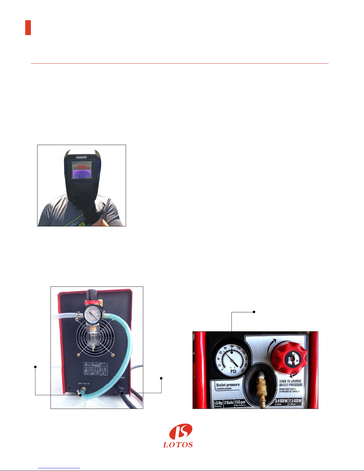
• Wear safety goggles at all mes. This will dark-
en the arc that is generated by the machine and
protect your eyes from harmful rays.
• All machine operators should be technically
cered for welding/cung.
Avoiding Harmful Smoke, Gases, and Vapors that can injure or kill.
Avoiding Harmful Arc Emissions/Rays that can burn eyes and skin.
Avoiding Fatal Electric Shock
Protect yourself and others from injury — read and follow these precautions.
Welding produces fumes and gases.
Breathing these fumes and gases can
be hazardous to your health.
7
• Do NOT switch o the machine while machine is
in operaon for internal circuitry can be
damaged.
• Wear appropriate clothing and a welding or
cung mask to protect your eyes and skin.
• Use appropriate screen or curtain to prevent
emissions from reaching individuals near the
work area.
• Ensure that your working area contains no
ammable items; and that none are nearby.
Cauon: Welding and cung spray can ignite.
Avoiding Harmful Noises that can damage hearing.
Noise from some processes can
damage hearing.
• Wear protecve earplugs while operang
machine.
• Isolate yourself from both the
earth and the work piece.
• Make sure that your working area is
nonammable and explosive-free.

®
Burn Protecon: HOT PARTS can cause serious burns.
Protect eyes from FLYING METAL or DIRT.
PACEMAKERS AND WELDING: MAGNETIC FIELDS can aect implanted devices.
CYLINDER HANDLING: it can explode if damaged.
Welding or Cung can cause Fire or Explosion.
If you encounter any dicules during set up or operaon:
• Consult this manual.
• Contact Lotos Customer Service by vising
hp://www.uwelding.com/about-us/contact-us/.
The work piece and equipment
get hot. The hot metal, hot work
piece, and hot equipment can
cause burns.
• Welding, chipping, wire
brushing, and grinding cause
sparks and ying metal.
Electric arc welding and cung
processes produce intense electric
and magnec (electromagnec)
elds. The funcon of pacemakers
can be aected by strong electro-
magnec elds.
Shielding gas cylinders contain gas
under high pressure. If damaged,
a cylinder can explode. Be sure to
treat gas cylinders carefully.
Welding, cung, and allied pro-
cesses can cause re or explosion
if precauonary measures are not
followed.
• Use approved helmets or hand shields that
provide protecon for the face, neck, etc.
• Wear approved safety goggles or glasses with
side shields, even under your helmet.
• Wear approved safety glasses with side shields,
even under your welding helmet.
• Persons with a pacemaker should not go near
welding or cung operaons unl they have
consulted their doctors and obtained informaon
from the manufacturer of the device.
• Protect compressed gas cylinders from excessive
heat, mechanical shocks, physical damage, slag,
open ames, sparks, and arcs.
• Install cylinders in an upright posion by securing
to a staonary support or cylinder rack to prevent
falling or pping.
• Develop adequate procedures, and use proper
equipment to do the job safely.
• Keep cylinders away from any welding or other
electrical circuits.
• Wear dry, hole-free insulated gloves.
• Remove combusble materials from a sphere
with a minimum radius of 35 feet around the
work area or move the work to a locaon well
away from combusble materials.

®
Equipment
General Overview
Manufactured with advanced inverter technology, the CT520D mulpurpose unit includes the following
features: stable output, reliable, completely portable, high-eciency and low noise generated while
cung.
The CT520D mulpurpose unit oers a variety of welding and cung aspects. It is able to cut all types of
metal up to 1/2’’ with the 50A plasma cung funcon. This LOTOS mul-process welder can switch
between AC/DC TIG Weld and AC/DC STICK Weld quickly and easily. With a hand carrying weight of
32lbs, the unit is portable and reliable featuring a duty cycle of 60% at max amps on all processes.
Main Characteriscs
The LOTOS CT520D series DC TIG, MMA, and plasma cuer allows you to weld stainless steel, alloy steel
and carbon steel and other nonferrous metals.
9
• Stabilizaon
• Reliability
• Portability
• Power eciency and low noise output
• High cung speed
• Smooth cuts
General
Model name CT520D
Functions
50 A Plasma Cutter
200 A TIG Welder
200 A STICK Welder
Dimension with handle
Weight 32 lbs (14.5 kg)
Input voltage 110-220 V, 1-PH, 50/60 Hz
Power supply type Inverter- IGBT
Housing protection IP21
Insulation B
Efficiency 85%
Accessories
Plasma cutting torch 50 A, 12.5 ft. (3.81m)
TIG welding torch 200 A 12.9 ft. (3.93m)
Arc/Stick clamp 200 A 6.5 ft. (1.98m)
Argon regulator 0-250 psi
Air regulator 0-150 psi
Specicaons

Plasma
Cutting
Rated input power requirement 120-220 V, 1-PH, 27 A
+/- 15%, 50/60 Hz
Output current 10-50 A @220V
10-25 A @110V
Duty cycle @ 40°C (104°F) 60% @ 50 A
100% @ 40 A
Gas supply Clean, dry, oil-free air
Recommended gas inlet
flow rate / pressure
3.6 scfm @ 65 psi
80L/min
Max rated cutting thickness 1/2 inches (12.7mm)
DC
TIG
Welding
Rated input power requirement 120-220 V, 1-PH, 17 A
+/- 15%, 50/60 Hz
Output current 10-200 A @ 220V
10-100 A @ 110V
Material can weld Steel, Stainless, Moly, Ferrous
Duty cycle @ 40°C (104°F) 60% @ 200 A
100% @ 150 A
No load voltage 62 V
Working voltage 16.9 V
Gas supply Clean, dry, oil-free argon gas
Starting mechanism High Frequency Start / HF Welding
Recommended gas inlet
flow rate 2-5 L/M
DC
Stick
Welding
Rated input power requirement 120-220 V, 1-PH, 23 A,
+/- 15%, 50/60 Hz
Output current 10-200 A @ 220V
10-80 A @ 110V
Material can weld Steel, Stainless, Moly, Ferrous
Duty cycle @ 40°C (104°F) 60% @ 200 A
100% @ 95 A
No load voltage 62 V
Working voltage 25 V
Starting mechanism High Frequency Start / HF Welding
Specicaons
10
®

®
Torch Type Model Amperage Consumables Type
5 prong LCON
Cutting Torch CL0105 50
LCON0120
LCON0140
LCON0190
Extended 5 prong
LCON cutting
torch
CL0205 50
LCON0220
LCON0240
LCON0290
Part Number Nozzle Electrode Shield Cup Swirl Ring Package Type Total Pieces
LCON0120 LN01 LE01 LC01 LR01 LN01 x 10,
LE01 x 10 20
LCON0140 LN01 LE01 LC01 LR01
LN01 x 10,
LE01 x 10,
LR01 x 10,
LC01 x 10
40
LCON0190 LN01 LE01 LC01 LR01
LN01 x 40,
LE01 x 20,
LR01 x 20,
LC01 x 10
90
LCON0220 LN02 LE02 LC02 LR02 LN02 x 10,
LE02 x 10 20
LCON0240 LN02 LE02 LC02 LR02
LN02 x 10,
LE02 x 10,
LR02 x 10,
LC02 x 10
40
LCON0290 LN02 LE02 LC02 LR02
LN02 x 40,
LE02 x 20,
LR02 x 20,
LC02 x 10
90
Torch Type
Consumables Package
11

®
Figure 2.1: Adjustor Diagram 1
Figure 2.2: Adjustor Diagram 2
Figure 2.3:
Air Regulator Conguraon
12
Amp Display Amp Adjusting
2-step &
5-step Switch
Machine/
Pedal Switch
Function
Switch
Problem
Indicator
Connect to
Air Compressor
Air
Regulator
Power
Cord
Power
Switch
(TIG)
(Stick)
(Cutter)

®
Figure 2.3:
Plasma Cung Diagram
Figure 2.4:
TIG Welding without Foot Pedal Diagram
13
Power
Cord
Adjust to
Plasma Cut
Gas & Power
Output
Gas & Power
Output
5-pin
Plug
5-pin
Plug
Ground
Cable
Ground
Clamp
Ground
Clamp
Work
Piece
Work
Piece
Cutting
Torch
TIG Torch
220V Round Plug
220V Round Plug
Air
Compressor
Argon
Tank
Argon
Hose
Argon
Regulator
Power
Cord

®
Figure 2.6:
Arc/Sck/MMA Welding Diagram
Figure 2.4:
TIG Welding with Foot Pedal Diagram
14
220V Round Plug
Argon
Tank
Argon
Regulator
Argon
Hose
Power
Cord
Gas & Power
Output
5-pin Plug
(unplugged)
Foot Pedal with
5-pin Plug
Work
Piece
Ground Clamp
TIG Torch
220V Round Plug
Work
Piece
Ground Clamp (+)
Arc Handler (-)

®
INSTALLATION
Connect this welding & cung equipment with a power supply of 110 or 220V AC.
For the wiring, please note that:
For 110VAC,
- The green wire with yellow stripe is the ground wire
- The red/brown wire is the hot wire
- The blue/black wire is the neutral wire
For 220VAC,
- The green wire with yellow stripe is the ground wire
- The red/brown wire is posive 110VAC
- The blue/black wire is negave 110VAC
Connect the earth terminal with the earth cable (minimum diameter of 2.5 mm2.)
1. Install welding torch according to the quick setup guide.
2. Connect the one-knob connector, air plug to the corresponding connector on the panel
board; and fasten the screw.
3. Plug the air plug of the back cable to “+” of the air socket on the panel board; and fasten it in
clockwise. Connect earth clamp with work piece.
If the power switch is on, the built-in fan starts working and the current meter displays the
current value.
The funcon switch enables the machine to alternate between MMA, TIG, and CUT welding
according to the praccal welding task requirement.
1. TIG Welding Funcon
- Connect the copper nozzle in the back of the machine to the argon tank with the hose. The
gas supply system includes the gas bole, air regulator, and gas hose. Connect the parts of the
gas system rmly to prevent gas leakage.
- Install the argon torch according to the Figure 3.2.
- Connect the copper screw on the cung torch to the output terminal of the one-knob of the
front panel; and fasten it clockwise to avoid gas leakage.
- Connect the plug of the closed circuit to the “+” socket on the panel board. Connect the earth
clamp to the work piece.
Funcon Switch
Power Cord Plug Wiring
Connecon of the Output Cables
Power Supply Switch
15

®
Funcon Switch
Welding Current Output Seng
Air/Argon Regulator Installaon
2. MMA Funcon
- Connect the plug of the electrode holder to the “+” socket on the front panel.
- Connect the plug of the ground clamp to the “-” socket on the front panel.
3. Plasma Cung Funcon
- Use the gas hose to connect to one of the terminals on the air regulator and connect the
other terminals to the copper tub.
- Connect the copper nut of the cung torch to the knob on the panel board. Connect the plug
of the ground clamp to the “-”socket on the front panel.
According to praccal demand, set the parameters of the current output by the operaon of
“ARC,” “TIG,” or “CUT.”
16
25
20
15
10
5
1
SHUT
REGULATOR
AR
OPEN
Figure 3.1:
Gas Regulator Installaon
Figure 3.2:
Argon Installaon
(Unassembled)
(Assembled)

®
OPERATION
TIG Welding Funcon
1) While this welding & cung equipment is operated, the power supply indicator is on; and
the built-in fan will funcon.
2) Switch to the TIG welding funcon mode.
3) Press the gas release buon and modulate the volume of gas output to the required value.
4) Press the buon on the welding torch, and the electromagnec valve funcons. The sound
of releasing electricity is audible, and there is gas coming out of the welding torch.
Please note: Before the inial welding operaon, press the welding torch buon for several
seconds in order to remove the gas inside the gas tub, and the welding operaon can begin.
There is gas output within a few seconds aer the welding operaon, that is a special design
to protect the welding point before it cools down. Therefore, aer the arc is gone, maintain
the welding posion unl the heat produced during the welding operaon dissipates.
17
MMA Funcon
1) Switch to MMA welding mode.
2) While this welding & cung equipment is operated, the power supply indicator is on and
the built-in fan will funcon.
3) According to the thickness of the work piece, adjust the welding current output and choose
the rod, then the MMA welding can begin.
5) The welding current output is adjustable, according to the thickness of the welding material
and required crasmanship.
6) Maintain a distance of 1-4mm between the tungsten electrode and the work piece. Press the
welding torch buon. HF electricity will release between the welding electrode and the work
piece. Aer the arc starts, the splash of the HF arc will vanish and the welding operaon can
begin.
Table of contents
Other LOTOS Welding System manuals
Popular Welding System manuals by other brands

INNO
INNO VIEW 5 Pro user manual

Neilsen
Neilsen CT2230 user manual

Lincoln Electric
Lincoln Electric INVERTEC 400TPX Operator's manual

Miller Electric
Miller Electric Welding Generator 250 DX Brochure & specs

BINZEL-ABICOR
BINZEL-ABICOR ABIPLAS WELD CT operating instructions

Strata
Strata ADVANCEARC 400 operating instructions