Loup Electronics Weighlog 100 Instruction Manual

Weighlog 100
Onboard Weighing System
User Guide
Installation Manual
Issue Date 1/2007
Loup Electronics


Service and Technical Support
PLEASE CONTACT YOUR NEAREST DISTRIBUTOR
If unknown Contact Loup Electronics
2960 North 38th Street
Lincoln, NE. 68504
Phone: 402-464-7131
Fax: 402-464-7104
Toll Free: 877-489-5687
© Copyright Loup Electronics Inc. 2006

Contents
1. Overview 3
2. Load Sensor Installation 6
2.1 Load Sensor 6
2.2 Installing Load Sensor 7
2.3 Mounting Load Sensor 9
3. Ref/Dir Sensor 10
3.1 Sensor Orentation 10
3.2 Sensor Mounting 11
3.3 Sensor Wiring 12
4. Remote Enter Switch 13
4.1 Switch Mounting 13
4.2 Switch Wiring 13
5. Head Unit 14
5.1 Head Unit Mounting 14
5.2 Head Unit Mounting Locations 15
6. Junction Box 16
6.1 Junction Box Head Unit Connection 16
6.2 Junction Box Mounting 17
7. Power Supply 18
8. Wiring 19
Page 2

OVERVIEW
Page 3
Weighlog Kits and Contents
Head Unit
Mounting Kit
Weighlog 100
Head Unit
Weighlog 100
Junction Box
Reference/Direction
Sensor Kit Pressure Sensor Kit
Power Supply Kit Remote Enter
Switch Kit
Tee Adaptor
Fitting Kit

OVERVIEW
Page 4
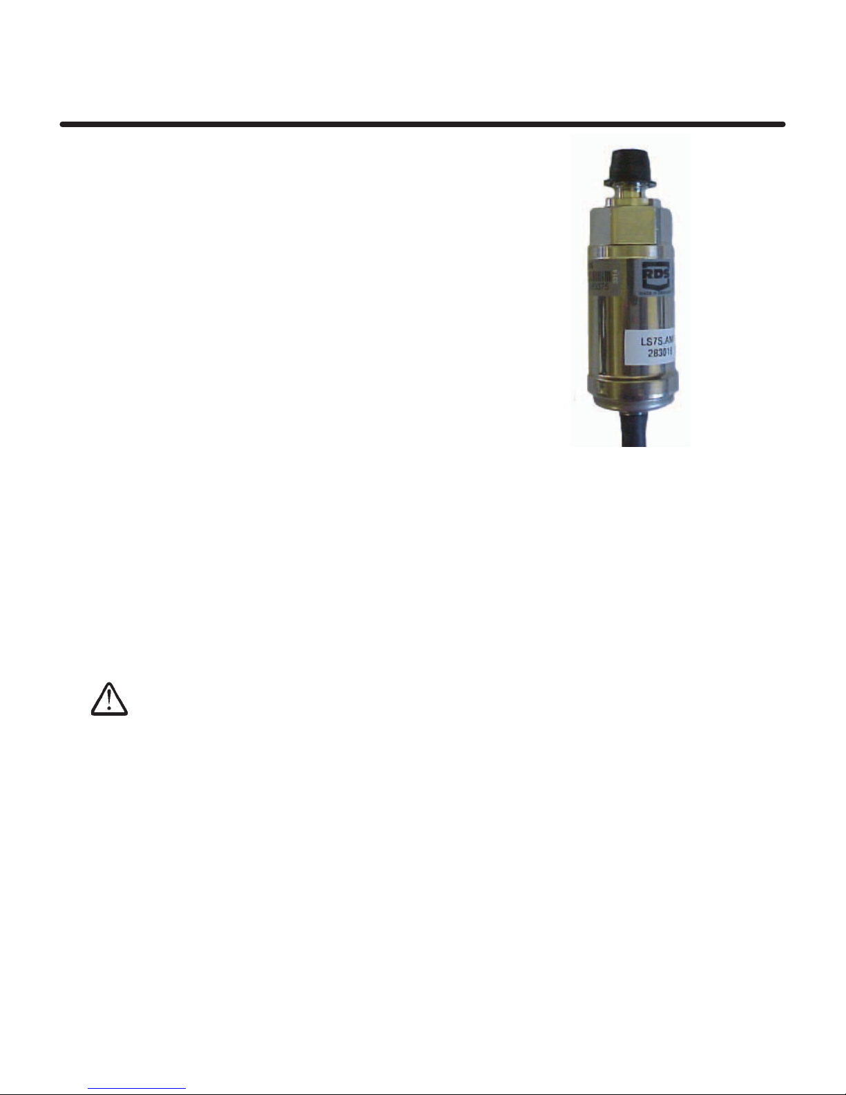
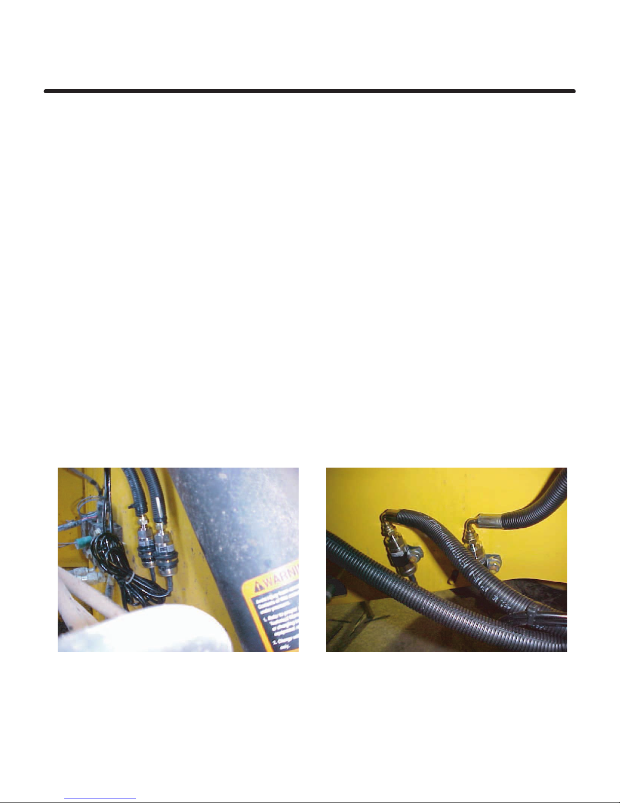
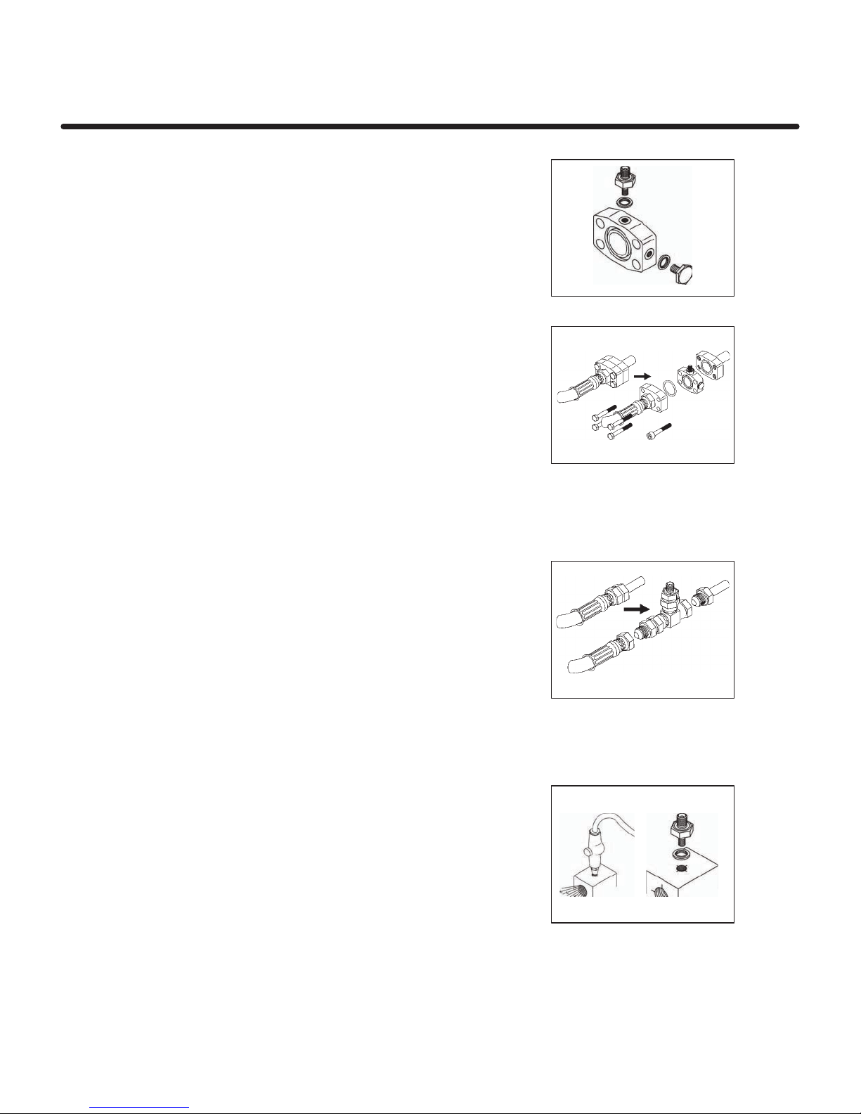
Load Sensor: This is either a 250 bar rated pressure sensor installed in the lift cylinder
hydraulic circuit, or in some instances a strain sensor mounted on the top side of the lift arm
(example: on certain telescopic handlers).
Reference/Direction Position Sensor: The pressure/strain must be measured
with the Lift arm in the same position each time. The reference/direction sensor is mounted near
the lift arm pivot point. It senses when the lift arm is in the correct weighing position, and if the
load is being lifted or lowered. The sensors are triggered by a magnet mounted on the side
of the lift arm.
Remote Enter button: This is mounted next to the lift lever and is used to record
the bucket weight, clear the channels and used in the zero bucket routine.
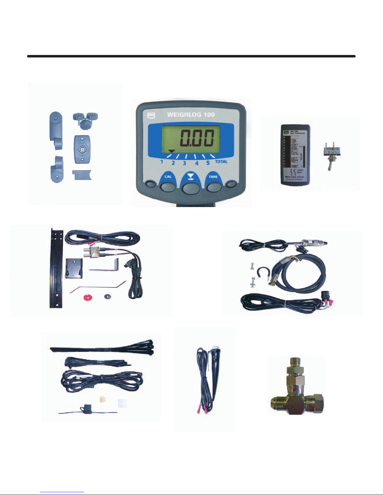
Head Unit and wiring: The head unit is supplied with a universal mounting bracket
assembly allowing it to be mounted in almost any configuration. A single multi-conductor lead
connected to a small Junction Box. Sensor and power connections are also made at the junction
box. The junction box has mounting holes if required.
The Weighlog 100 is intended for use on industrial and agricultural loaders; Such as Skid steers,
Small wheel loaders and some Telescopic Handlers.
It measures, displays and records the net weight lifted, based on the lift system hydraulic
pressure. Pressure sensing is problematic on certain types of equipment due to the design of the
hydraulic system. In these instances strain sensing technology may be used instead.
Overview
System Components
Important Safety Precautions !
In addition to observing site safety requirements, before working on the machine always:-
Make sure that the bucket is down on the ground and all pressure is released from the
hydraulic system, before loosening any hydraulic coupling or fitting.
To Prevent the machine from being accidentally started while working on it, Always
remove the ignition key.
Keep other persons in the vicinity of the machine fully aware of your intentions during
installation and initial calibration.

OVERVIEW
Page 5
The Weighlog system consists of a number
of standard kits, which are designed to fit a
wide range of loaders.
Mounting positions will vary according to the
type of machine, however this manual gives
general guidelines that apply to all machines.
The installation may require some modification
of the brackets provided for mounting the
reference/direction sensors. Normal
installation requires only basic handtools.
Typical Mounting Positions Shown
1. Pressure Sensor
2. Strain Sensor (Optional)
3. Reference/Direction Sensor
4. Magnet
5. Head Unit
6. Remote Enter Button

LOAD SENSOR
Page 6
Load Sensor
The load sensor (fig. 2a) is connected by
a flexible hose into the pressure side of
the hydraulic circuit, using a tee fitting.
Depending on the machine, you may be
using a threaded tee piece, SAE flange
coupling, or if there is no suitable
coupling you may have to drill and tap
into a suitable point.
The machine is normally specified when
ordering a Weighlog kit so the correct
adaptor should be in the kit.
Where to tee in
Identify the lift hose on one of the main lift cylinders. Trace the lines back toward
the valve block , (at some point the lines from the other cylinder will join into a
single line). Identify a suitable coupling which allows enough room to be split and
the tee adaptor to be inserted, or in the absence of a suitable coupling, a point
which can be drilled and tapped. The tee in points could be anywhere between
the lift cylinder and the valve block but ideally should be as close as possible
to the lift cylinder.
1.
Make sure that the bucket is down on the ground and all pressure is released
from the hydraulic system, before loosening any hydraulic fitting! Always
loosen or open the cap on the hydraulic tank to help release any pressure.
2. Thoroughly clean around the tee in point before splitting, to prevent the ingress
of dirt into the system.
3. Make sure that the tee in point will allow the hose to reach the load sensor
mounting location. The load sensor needs to be mounted up under the machine
where it is protected.

LOAD SENSOR
Page 7
Installing the Load Sensor
The load sensor contains a snubber to protect if from shock loading. This consists
of a diagonally drilled hole 0.3 mm in diameter. It is possible to block this hole with
debris causing the sensor to malfunction.
If a load sensor is installed on a machine where there may be particles of debris
in the oil, or the installer is unable to ensure the components being installed are
kept clean, it is advisable to pre fill the flexible hose with clean oil.
When a load sensor is installed the first supply of oil also contains all the debris and
contamination in the lines feeding it. Once this line has filled there is no flow of
oil and consequently no risk of contamination arriving at the sensor. In order to avoid
this problem we recommend that if you suspect there is the possibility of contamination
in the oil then please ensure the hose feeding the sensor is pre filled with clean oil.
Please note that the pressure sensor must be mounted with the hose connection at the
top, so that all the air can bleed out of the sensor. If you do not mount the sensor as
illustrated below premature failure may occur due to air being trapped inside.

LOAD SENSOR
Page 8
SAE Flange Coupling
1. Install the 1/8" x 1/4" BSP adaptor and Dowty
seal to one of the two 1/8" BSP ports on the
flange. Install the plug with Dowty seal to the
remaining BSP port (Fig1).
2. Loosen and remove the four flange bolts and
split the coupling. Insert the flange plate
ensuring the "O" rings are properly seated
and that the 1/4" BSP port is in a convenient
location.
3. Replace the hose using the longer bolts supplied
in the kit. Use caution to ensure the "O" rings stay
in place. Check the orentation of the fittings that
they allow room for tighening and hose connection
(Fig2).
Torque the bolt to manufactures recommendation.
If this is not know use the following torques:
3/4" Flange 21-29 ft-lb
1" Flange 27-35 ft-lb
11/4" Flange 35-45 ft-lb
Fig 1
Fig 2
Threaded Tees
1. Install the 1/4" BSP adaptor tee in the location
selected. BSP, JIC, Metric and ORFS fittings are
available.
2. Loosen and remove the hose and install the
fitting into the line as shown in (Fig3).
Fig. 3
Tapped Port
In cases where there is no suitable coupling, you must drill
and tap a 1/8" BSP port into a convenient block or fitting.
If possible remove the component to be drilled.
Center punch and drill a 3mm pilot hole. Then open out to
8.8mm and tap with 1/8"BSP tap.
Ensure all cuttings are flushed out of the line, then install the
1/8" x 1/4" BSP adaptor with dowty seal as shown in (Fig4). Fig. 4

LOAD SENSOR
Page 9
Mounting the Load Sensor
1. Connect the hydraulic hose to the tee
fitting and route the hose towards the
sensor mounting location. Connect to
the load sensor and mount the sensor
in a well protected area, one that can
also be accessed for servicing.
NOTE:Mount the pressure sensor in a well
protected area, in an upside down
position as shown. This helps prevent
air bubbles from hitting the load
sensor diaphragm.
Bleeding the Load Sensor
This can be done whenever convenient during the installation procedure.
Lift the boom so that it is a few inches off the floor. Have an assistant loosen
the hydraulic fitting to allow any air to escape. You may have to bleed the
sensor more than once. It is recommended that the machine is worked for
5 to 10 minutes and then the bleeding procedure be repeated.
Load Sensor Connection
2. Connect the extension cable to the weatherpack connector on the sensor lead and
route back to the Junction box. Cable tie wires securely to existing
hydraulic lines or hoses.
Avoid coiling excess cable. Leave a small amount of slack at the sensor for movement.
If the sensor cable is long enough to reach the J-Box then make a short pig tail with
the extension cable rather than cutting the sensor cable.
3. Connect the wires according to the label
on the Junction box lid.
Color Function Terminal #
Red +V 10
Blue oV 9
Green Signal 8
NOTE: There is no provision for strain relief on these connections. Its recommended that
sensor cables are cable tied back very near the junction box.
12
11
10
9
8
7
6
5
4
3
2
1

Reference/Direction Sensor
Page 10
Reference/Direction Sensor
First establish the most convenient weighing
position. If possible sensor position should be
at the middle of the lift height. In some cases
this is not possible. Position the sensors so
the weight reading will be obtained as high
as possible .The sensor and magnet must be
arranged so the magnet is opposite the sensor
face at the weighing position. The sensors are
identified by the tags "R"for Reference and
"D" for Direction Sensor.
NOTE: If you take the sensor clamp apart when
the sensors are reassembled the direction
sensor must be on the bottom (first sensor
the magnet will pass).
1. Lift the bucket to the height you want the
weight reading to be taken.
2. General purpose mounting bracketsare
provided which can be modified if
necessary. The sensor can be mounted
parallel or at right angles to the lift arm.
Itsrecommended that the sensor be
positioned at least 10 inches from the lift
arm pivot point.
The magnet should pass the end of the
sensor, 1/4" to 1/2" away from the sensors
as shown.
Use caution positioning the brackets
to ensure they will not interfere with
the lift arms when fully raised!
1/4" to 1/2" inch
10 inches

Reference/Direction Sensor
Page 11
Reference/Direction Sensor Mounting
3. Assemble the Reference/Direction clamp assembly as shown.
The bracket is designed so that the sensor may be installed
on either side of the machine, by rotating the angle bracket 90
degrees.Remove the original M8 bolt from the green nylon clamp,
and replace it with longer M8 x M60 mm. Then tighten with the
sensors in the correct position.The clamp with sensors should
then be inserted into the clamp holder, and tightened into position
using the M8 self-locking nut supplied.The whole assembly can
then be bolted to the angle bracket at the suitable angle for
the specific installation, using the two M6 x 16mm bolts and nuts
provided. Mounting locations vary by machine type shown below
are mounting options.
Skid Steer top rear of cab Skid Steer front of cage
Small Wheel Loader lift arm pivot point Small Wheel Loader lift arm pivot point

Reference/Direction Sensor
Page 12
Reference/Direction Sensor Mounting
Magnet mounting
Mark the hole positions drill and tap 2 holes M6 in the lift arm for the magnet
bracket. In some cases the magnet can be mounted directly onto the lift arm
but you must install the fiber washer between the magnet an the lift arm.
Install the bracket and attach the magnet using the stainless steel screw and
the fiber washer between the magnet and bracket.
Do not drill the lift arm above the centerline of the lift arm!
Ref/Dir Sensor Connection
Connect the extension cable to the
Weatherpack connector on the sensor
lead, route the cable back to the
junction box. Secure the cable with
wire ties to avoid damage to the cable.
Connect the wire according to the label
on the Junction Box lid.
Color Function Terminal #
Blue Common 6
Green
Red Ref. Sig. 7
Yellow Dir. Sig. 4
12
11
10
9
8
7
6
5
4
3
2
1

Remote Enter Switch
Page 13
Remote Enter Switch
Mount the Remote Enter Switch either on
the lift lever using a hose clamp or wire
ties, or mount with screws provided
within easy access of the operator.
Connect the wires according to the label
on the Junction box lid.
Color Function Terminal #
Blue 0v 3
Brown Signal 1
Remote Enter
12
11
10
9
8
7
6
5
4
3
2
1
External Alarm
An External alarm is optional. Mount the
alarm buzzer where it will stay dry.
Connect the wires according to the label
on the Junction box lid.
Color Function Terminal #
Blue 0v 9
Brown Signal 11

Head Unit
Page 14
Head Unit
Confirm with the machine operator on where to mount the head unit in the cab.
The head unit has a 3 foot gray cable with a 18 pin IDC connector, ready for
connection into the Junction Box.
Mounting the Head Unit
The head unit is supplied with a seperate
mounting kit including the following parts.
1 Long Bracket
1 Short Bracket
3 Clamping Knobs
1 Cover Plate
1 Mounting Plate
2 Self Tapping Screws
1. Snap the cover plate into the recess of the
long bracket.
2. The bracket kit is designed to offer maximum
flexibility in positioning the head unit, from the
right or left side of the cab, the dashboard or
from an overhead position.
Assemble the two brackets, and mounting
plate with clamping knobs, and attach to
the head unit.
As you will notice, you can index each
pivot point on the mounting bracket to
angle the head unit in relation to the
mounting plate.
3. After establishing the orientation of the
bracket, attach the mounting plate to the
cab with the self tapping screws provided.
If you are installing the mounting plate to plastic like the dashboard or other cab
moulding, its recommended you use machine screws with washers or plate the
back for added strength.
Never Drill into a ROPS frame. Do not attempt to adjust the
mounting bracket without
first loosening the clamp
knobs. You will only succeed
in damaging the bracket.

Head Unit
Page 15
Remote Enter
Head Unit Mounting
Optional Mounting Locations

Junction Box
Page 16
Remote Enter
Junction Box
The Junction Box provides connections for
the 18 conductor head unit cable, all the
sensors and the power supply.
The Junction Box is not sealed. It should be
located where is will be protected for
excessive moisture and dirt.
1. The Junction Box can be mounted using the
screws provided, or left in-line with the cables.
2. Connect the head unit cable onto the PCB
header as shown.
NOTE:The red wire on the 10 way plug goes on
pin 1 of the connector.
The Blue/Red wire on the 8 way plug goes
on pin 11 of the connector.
3. Locate the cable grommet into the groove
in the juction box, cable tie the head unit
lead onto the moulded flange to provide
strain relief.
4. Connect the Sensors. The Wiring Connections
are printed on the lid of the Junction Box.
The connections are also shown in the
appropriate sections in the manual.
Red Wire Pin 1
Red/Blue Pin 11
Note: No means of strain relief
is provided for the sensor
cables. Its recommended
that you cable tie them
securely to prevent strain
on the screw terminal
connections.

Junction Box
Page 17
Remote Enter
Junction Box Mounting
Optional Mounting Locations

Power Supply
Page 18
Remote Enter
Power Supply
Blue Wire - Ground 0v
Brown Wire - Power +v
A toggle switch is provided
in the kit and must be used
if the power supply is not
keyed. The Weighlog unit
has no power button and
will remain on if the toggle
switch is not used. The
supply can be 12 or 24 volt
the system will operate on
either one.
Other manuals for Weighlog 100
1
Table of contents
Other Loup Electronics Accessories manuals
Popular Accessories manuals by other brands

Baader Planetarium
Baader Planetarium HYPERION Universal Zoom MARK IV instruction manual

TEC
TEC E Series operating manual

PRIMAVERA
PRIMAVERA Simply Silent Important information

Dudek
Dudek GROUNDMASTER user manual

Eaton
Eaton E57P Series Instruction leaflet

PCB Piezotronics
PCB Piezotronics T106B Installation and operating manual

Sensor Switch
Sensor Switch WSX 2P instructions

elsner elektronik
elsner elektronik WGTH-UP Technical specifications and installation instructions

ASM
ASM posiwire Installation and operation manual

Argo
Argo ARMONY operating instructions

StarTech.com
StarTech.com ST122DVIA user guide

Beacon
Beacon iB003N user guide