Loup Electronics Weighlog 100 User manual

Weighlog 100
Onboard Weighing System
User Guide
Calibration and Operation
Issue Date 1/2007
Loup Electronics


Service and Technical Support
PLEASE CONTACT YOUR NEAREST DISTRIBUTOR
If unknown Contact Loup Electronics
2960 North 38th Street
Lincoln, NE. 68504
Phone: 402-464-7131
Fax: 402-464-7104
Toll Free: 877-489-5687
© Copyright Loup Electronics Inc. 2007

Contents
Page 2
1. Overview 3
2. Maintaining Accuracy 5
2.1 Machine Requirements 5
2.2 Lifting Procedure 5
3. Initial Setup 6
3.1 Selecting Channel 6
3.2 Check/Change Display Readout 6
3.3 Weighing Methods 7
3.3.1 Dynamic Weighing 7
3.3.2 Static Weighing 7
3.4 Check/Change Weighing Modes 7
4. Check/Set Zero Weight 8
4.1 Check Zero Weight 8
4.2 Set Zero Weight 9
5. Calibration 10
5.1 Weight Calibration 10
5.2 Display/Change Calibration Factor 10
5.3 Calibration Procedure 11
5.4 Calibration Example 12
6. Reset Channels/Totals 13
6.1 Reset Channels 13
6.2 Reset Totals 13
7. Faults 14
8. Troubleshooting 15
9.Notes18

Overview
The Weighlog 100 is intended for use on skid-steer loaders, backhoe loaders
and small wheel loaders.
It measures, displays and records the net weight lifted, normally based on
sensing the lift system hydraulic pressure. Pressure sensing is problematic
on certain types of equipment due to the design of the hydraulic system. In
these instances strain sensing technology may be used instead.
There are 5 individual display channels available. These can be calibrated for
up to 5 different loader attachments or 5 different products. Each channel will
display the net bucket weight lifted at any time. If required the bucket weight
can be added to the total of the channel being used and will also be added to
the total channel, which accumulates weight from all of the 5 channels.
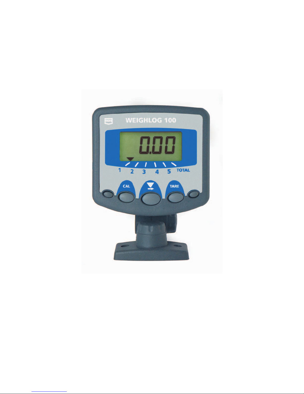
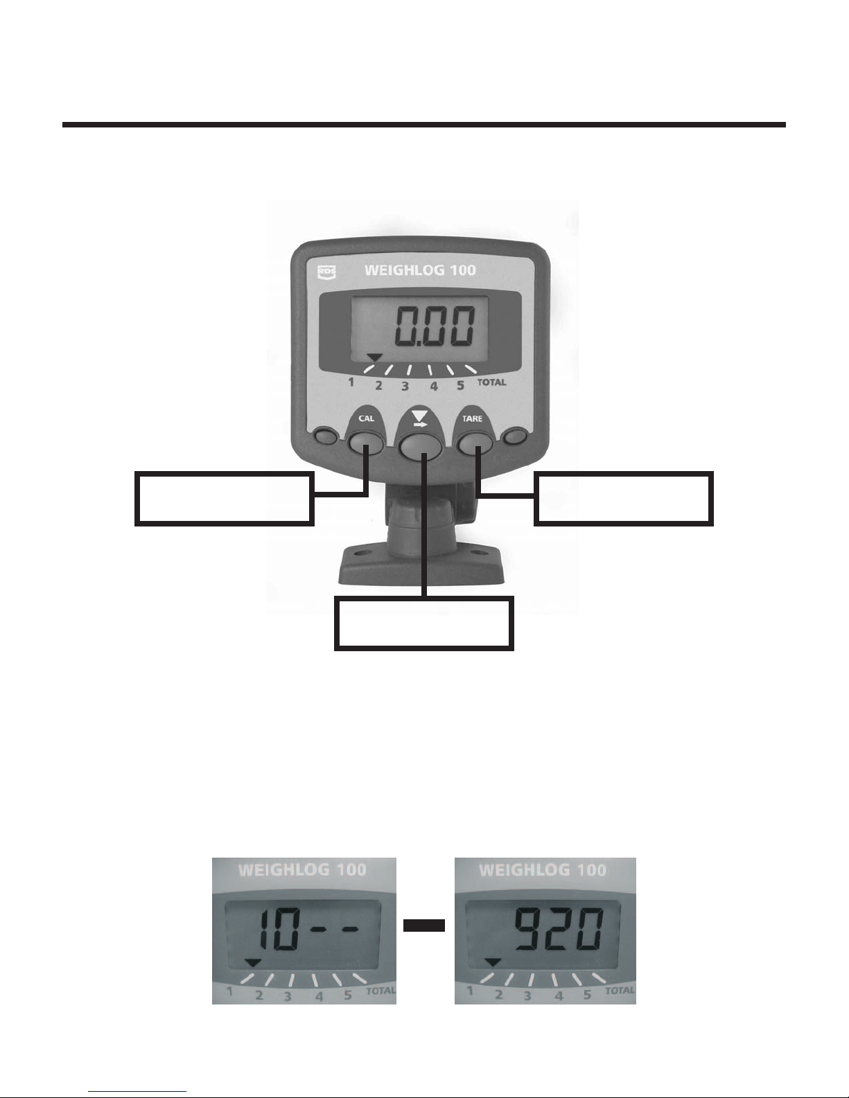
The instrument has an illuminated 4 digit LCD display, 3 front panel switches,
an external pushbutton and an internal alarm. An external audible alarm is
optional.
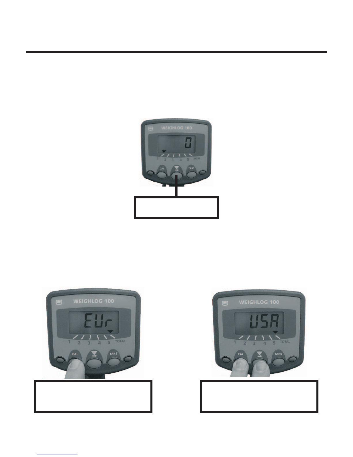
The instrument is normally powered on by the ignition switch and recalls the
function selected when last used.
With careful operation, system accuracy can be as good as + or - 1% of full load
although + or - 2% is more common practice.
Weighlog readings are not viewed "Legal for trade" in the US.
For each channel you can:
qadjust the Calibration Factor
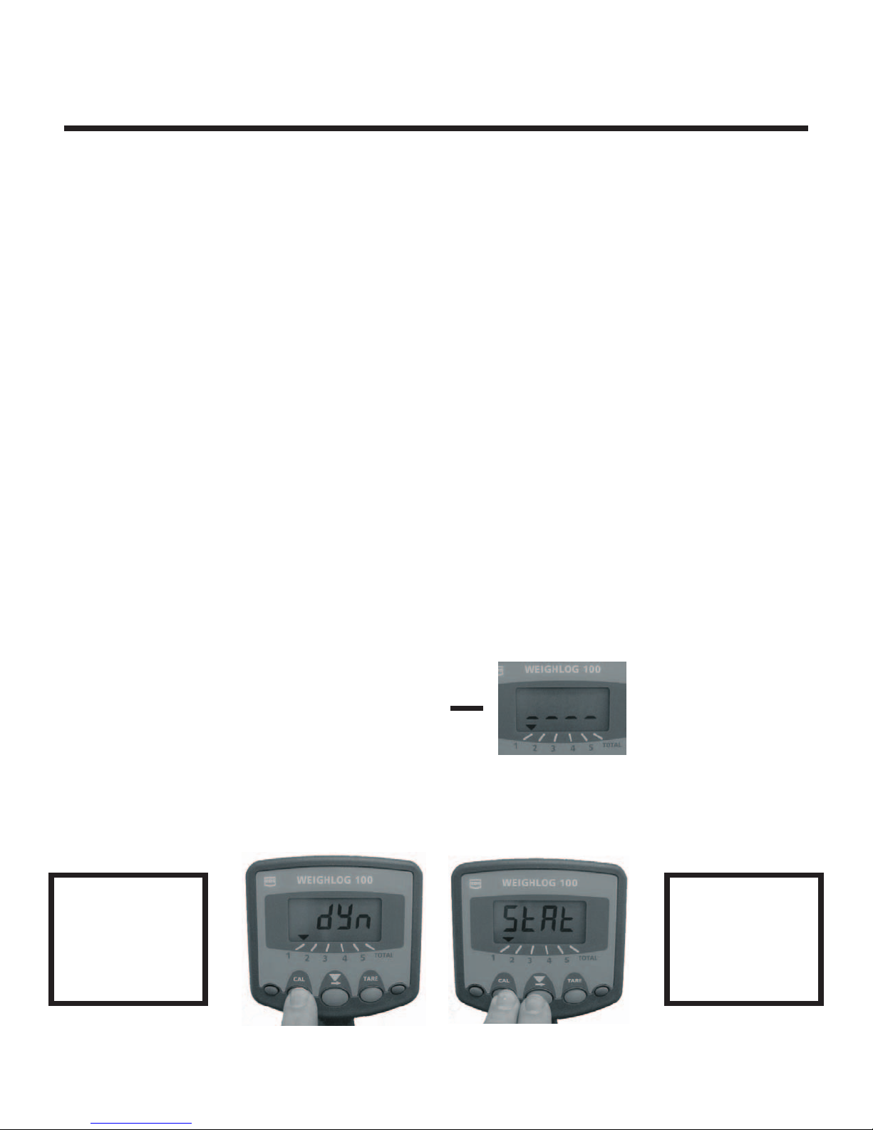
qselect either static or dynamic weighing modes
qset the Zero Weight (tare)
qdisplay and add the bucket weight to the sub-total
qreset the Sub-total
qreceive audible alarm confirmation of the tare and loading routines
Page 3

Overview
Page 4
The front panel has 5 buttons. Only the center 3 are used on the
Weighlog 100.
Enter Calibration
Mode
Set empty bucket
weight to zero
Select Channel
Display units
The instrument can display up to 9990tons, or 99,990 lbs. depending on mode selected.
When set to the "USA" or lbs. setting, the display will read up to 9990 lbs rounded to the
nearest 10 lbs. Above this weight reading the display will alternate between "lbs x 1000" and
any remainder. The instrument can display up to 99,990 lbs.
For Example, a total of 10,920 lbs the display will alternate between:

2 - Maintaining Accuracy
Page 5
The Weighlog translates pressure (or strain) to weight by means of a calibration factor
programmed into the instrument. The accuracy of the system depends to some extent
on the following:
2.1Machine Requirements
1. Operation Temperature: Always allow the machine and the hydraulics to warm
up to the normal operating temperature before weighing.
2. Weighing on level ground: Avoid weighing when on a slope or a side slope.
When ever possible weigh on a level surface.
3. Vehicle Movement: Best results will be obtained weighing while the
machine is stationary. It is important that the load does not bounce or jerk
as it is lifted.
4. Maintenance: Keep the machine maintained in good working condition. Things
like excessively worn bushings, piviot pins and hydraulic leaks, as well as the
lack of lubrication to grease points can have adverse effects on weighing accuracy.
NOTE: After any major service especially if you have replaced worn components or hydraulic
repairs, you should re-calibrate the system. If the hydraulic system has been drained
and re-filled you should also check for any air which may be trapped at the pressure
sensor.
2.2Lifting Procedure
The correct lifting procedure is especially important for dynamic weighing. The
load should be lifted smoothly and consistantly through the weighing position.
The engine speed should be the same for each lift when weighing.
The best procedure is as follows:
1. After picking up load or loading the bucket roll bucket back against the stops.
2. Throttle the engine to the proper RPM for weighing (the speed used to calibrate).
3. Pull the lift lever completely back and raise load smoothly without bouncing or
jerking. Continue to raise load through the weighing position (dynamic weighing)
or stop lift at the reference position (static weighing).

3 - Initial Setup
Page 6
3.1Selecting Channel
An indicator arrow at the bottom of the display points to the selected channel.
Press the center arrow button to select channel 1 thru Total the 5 channels can
be used for 5 attachments or 5 different products. If only one attachment is used
select channel 1.
Center Button used to
Select Channel 1-Total
3.2Check/Change Display Readout
The Weighlog 100 can be set to read Tons "Eur" setting or lbs "USA" setting. The
default setting is tons. If lbs readout is desired follow the steps shown below.
Use the center arrow button and scroll to the "Total" channel
Press and hold the "Cal" button
to display weight readout.
To change weight readout.
Hold the "Cal" button and tap
the Center arrow button.

3 - Initial Setup
Page 7
3.3Weighing Methods
There are two weighing methods Dynamic "Dyn" or Static "StAt" both are explained below.
3.3.1 Dynamic Weighing
Dynamic weighing means that the load is weighed without stopping the lift.
The load is lifted up above the reference/direction sensors. Dynamic weighing
can give consistant results without significantly slowing down the loading cycle,
but does require the operator to be smooth and consistant with the lifts.
1. Lift the load up above the Ref/Dir sensors, the alarm will beep once.
The display will then show the net weight in the bucket.
The weight will remain displayed until the bucket is lowered below the Ref/Dir sensor.
2. With the load in the weighing position press the remote enter button to add the weight
to the channel being used and also to the Total channel.
3.3.2 Static Weighing
Static weighing means that the load is weighed while the bucket is stopped
at the Reference sensor and held there. The display will show a "Live Reading"
which on some loaders may drop as the pressure decreases. You can tip off
excess material as required since at this point the reading is "Live".
1. Lift the load up to the Reference Sensor and stop. The alarm will beep once and
the weight reading is displayed. If you lift too high the display will show 4 dashes.
2. With the load in the weighing position press the remote enter button to add the weight
to the channel being used and also to the Total channel.
To select Dynamic "Dyn" or Static "StAt" select desired channel to be used
and follow the steps below.
Static Weighing Mode
bucket lifted too high
3.4Check/Change Weighing Modes
Select Channel.
Press the Cal.
button to
display weighing
mode.
To change mode.
Tap center button
while holding
Cal button.

4 - Check/Set Zero Weight
Page 8
4.1Check Zero Weight
You should check the zero weight of the bucket regularly as part of the daily
operating routine. ALWAYS check the zero weight if the machine has been
left idle for some time and has cooled down. Checking the zero weight before
the machine has warmed up some may result in false readings do to the oil
being cold. Best practice would be to exercise and warm the hydraulic system
before checking the zero weight.
Check Zero Weight (Dynamic Weighing Mode)
1. Ensure the bucket is empty. Roll the bucket back against the stops.
2. Lift the bucket up above the Reference/Direction Sensors. A single beep will
be heard and the display will show a weight.
3. If the display reads 0 or within + or - 20 lbs this is within the repeatability of the
Weighlog system and no further changes are needed. The system is ready
for operation.
4. If the display reads more than + or - 20 lbs then you should zero the weight.
Check Zero Weight (Static Weighing Mode)
1. Ensure the bucket is empty. Roll the bucket back against the stops.
2. Lift the bucket up to the Reference Sensor and stop. A single beep will
be heard and the display will show a weight. If you lift too high a second
beep will be heard and the display will show 4 dashes. If this happens
lower the bucket below the sensors and lift again.
3. If the display reads 0 or within + or - 20 lbs this is within the repeatability of the
Weighlog system and no further changes are needed. The system is ready
for operation.
4. If the display reads more than + or - 20 lbs then you should zero the weight.

4 - Check/Set Zero Weight
Page 9
4.2 Set Zero Weight
The bucket should be zeroed if the weight reading for an empty bucket
is more than 20 lbs. Ensure the hydraulic system is up to operating
temerature. It may be necessary to lift and lower the bucket a few times
to warm up the hydraulic system. Be sure to follow correct lifting procedure.
Set Zero Dynamic Weighing Mode
Step 1
Press and hold the "Tare"
button for 5 seconds then
release. Display will flash.
Step 2
Lift empty bucket up above
the sensors, weight reading
will be displayed.
Step 3
Press the Remote enter
button to zero the display.
Unit will beep and show 0.
Step 1
Press and hold the "Tare"
button for 5 seconds then
release. Display will flash.
Step 2
Lift empty bucket up to Ref.
Sensor and stop. Weight
reading is displayed.
Step 3
Press the Remote enter
button to zero the display.
Unit will beep and show 0.
Set Zero Static Weighing Mode

5 - Calibration
Page 10
5.1Weight Calibration
Accurate results from the Weighlog can only be achieved if the calibration
procedure has been carried out carefully and in the correct sequence.
You must set the zero weight of the empty bucket or forks and enter a
weight calibration factor for each channel to be used.
The calibration factor is an arbitary number relating the hydraulic pressure
in the lift system to the load in the bucket. This factor must be set independently
for each attachment as well as each channel of the Weighlog.
5.2Display/Change Calibration Factor
Once the bucket zero has been set and the system repeats a zero. A weight or
a bucket load of material that has a known weight will be placed in the bucket.
The calibration number is changed and fine tuned until the Weighlog reads
the weight in the bucket. The amount of weight which is used needs to be as
close as possible to the maximum weight the loader will be lifting. Using a couple
hundred pounds will result in a poor calibration.
Press and Hold the Cal
button after 3 seconds the
display will change to show
the cal #. Keep holding the
Cal button.
The Cal button must be
held until done. The digit
flashing is the one you can
change.
To make the next digit
flash tap the center button.
To change hold the center
button. Numbers will count
up 0-9.
Change Calibration Factor
You must keep the Cal button pressed until finished or the display will change
back to the operation screen. The digit flashing is the one you can change, to
select next number tap the center button.

5 - Calibration
Page 11
5.3Calibration Procedure
1. Decide which attachment or product applies to which channel. This can be
noted on the chart provided at the back of this manual.
2. Decide whether Dynamic or Static weighing will be used. Select the desired
channel and set to correct weighing mode (Section 3.3).
3. Start by setting the calibration factor to the maximum lift capacity of the loader.
Example: If the lift capacity is 2 tons then set the factor to 2.0.
4. Set the zero weight if not already done (Section 4.2).
5. Fill the bucket with a typical load, the weight of which is known or can be
determined with a scale.
Important: The best accuracy will be achieved by using a load that is at
least 75% of the capacity of the machine. Using only a couple hundred
pounds will result in a poor calibration.
6. Lift the bucket or forks a few times,noting the weight displayed each time.
Be sure to follow proper lifting procedures and roll bucket back before each
lift is made. The weight displayed should not vary by more than + or - 40lbs.
7. If not already known, determine the true weight of the load in the bucket.
8. The actual calibration factor can now be determined by a simple calculation
using the known weight and the weight displayed as follows:
Correct Factor = Existing Factor x True Weight
Weighlog Reading
9. Program the correct factor into the Weighlog (Section 5.2).
10. Lift the load again several times, checking the weight reading is correct and
repeats within tolerances.
11. The weight reading can be fine tuned if need by adjusting the calibration
number. Raise the number to make the scale read heavier and lower the
number to make the scale read lighter. Keep in mind the scale rounds to
nearest 10 lbs.

5 - Calibration
Page 12
5.4Calibration Example
Calibrating a skid steer loader with a capacity of 3000 lbs.
1. Set the inital calibration number to 1.500.
2. A bucket load is weighed and the Weighlog reading is 2500 lbs. The
known weight of the bucket load is 2100 lbs.
3. Using the correction calculation:
Correct Factor = Existing Factor x True Weight
Weighlog Reading
= 1.50 x 2100 = 1.26
2500
4. Reprogram Weighlog with new cal. number of 1.26.
If the Weighlog reading is more than the true weight, the factor is decreased,
if the Weighlog reading is less than the true weight, the factor is increased.
Therfore if you find a consistant difference between the Weighlog readings
and the scale readings, you can then "Nudge" the cal factor up or down as
needed.

6 - Reset Channels/Total
Page 13
6.1 Reset Channels
Channels 1 thru 5 can be reset independently.
1. Select the correct channel 1 thru 5
2. Press and hold the remote enter button for 5 seconds. The display will flash
5 times and then reset to 0.
This does not affect the TOTAL channel.
6.2 Reset Total
1. Select the TOTAL channel
2. Press and hold the remote enter button for 5 seconds. The display will flash
5 times and then reset to 0.
Select correct
channel 1 thru 5.
Press and hold the
remote enter button.
Select the
Total channel.
Press and hold the
remote enter button.

7 - Faults
Page 14
7.0Faults
Error Message: "Prog"
The instrument memory has been corrupted. You can attempt a "Power on
reset".
1. Switch off the power supply.
2. Press and hold all three center buttons and switch the power on. If the instrument
can recover itself, it will perform a short self test routine and return to the normal
display. If not contact your local Loup Electronics dealer.
NOTE: All calibration settings, sub-totals, grand total and weighing units will be reset
to the factory default settings.
Error Message: "Err"
If the display shows "Err" there is no pressure signal being received by the scale.
This indicates either a bad connection, wiring or a faulty pressure sensor.
Visualy inspect the wiring and connections first, then if necessary check
continunity of the sensor lead wires between the Junction Box terminals and the
3 pin weatherpack connector on the load sensor extension cable. If no fault is
found contact your local Loup/RDS dealer.

8 - Troubleshooting
Page 15
8.0Troubleshooting
Symptom Possible Problem Correction
Head unit does not Magnet is not close enough to Adjust sensor and/or magnet
"Beep" when bucket the Reference/Direction Sensors. to within 1/4" to 1/2" maximum.
is lifted.
Reference and Direction Sensors Sensor relationship must be
improperly installed. vertical not horizontal with the
"D" sensor on bottom.
Improper wiring and/or Check cable and connections
cable connections. at sensors and J-box terminals.
Reference/Direction Sensor
Yellow wire - Terminal 4
Blue-Green - Terminal 6
Red wire - Terminal 7
Load Sensor
Green wire - Terminal 8
Blue wire - Terminal 9
Red wire - Terminal 10
Magnet location incorrect Be sure magnet is below sensor
1-2 in. with bucket on ground.
Faulty or broken Ref/Dir Sensor Contact dealer for replacement
Head unit "Beeps" when Ref/Dir sensors improperly installed Sensor relationship must be
bucket is lowered. vertical not horizontal with the
"D" sensor on bottom.
Four dashes displayed "----" Check Weighing mode. Scale set to "Static" weighing
mode bucket position too high.
Scale does not weigh correctly. Incorrect weighing mode selected Static mode raise bucket unitl
(see also accuracy) beeps and stop. Dynamic mode
raise bucket up and past sensors.
Bucket reads above or below Empty bucket weight not set to zero Perform zero routine. Press and
zero when lifted with no weight hold the "tare" button for 5
seconds display will flash.
Lift empty bucket up to or
past Ref/Dir sensor and press
remote enter button to set zero.
Head unit displays 2 numbers This is normal scale operation. Display will only show 4 digits.
and dashes followed by numbers. Over 9990 displays as follows:
10500 is displayed as 10-- first
then 500. Display will alternate
between the numbers.

8 - Troubleshooting
Page 16
8.0Troubleshooting
Symptom Possible Problem Correction
Accuracy Incorrect bucket position. Bucket must be rolled back
completly before each lift.
Incorrect calibration number. Most 100 applications will
have a Cal. No of 1.0-4.0
make sure decimal point is
in correct place. To make
scale reading heavier raise
the Cal No. To make the
scale read lighter lower the
CalNo.
Incorrect lifting method. Model 100: Weights can
vary depending upon lift
speed. Choose a lifting
speed and weigh the same
eachtime.
Incorrect load positioning With forks and grapples the
load must be centered and
as close to the machine as
possible.
Incorrect weighing units selected With bucket on ground
display shows 0.00 unit
is set to weigh in tons. If
display shows 0 unit is
set to weigh in pounds.
Incorrect channel selected Be sure correct channel
is selected for bucket or
attachment used. If only 1
bucket or attachment is
used set all 5 channels to
correct Cal. No.
Incorrect load sensor installation Be sure the load sensor
is installed in the pressure
side of the lift cylinder not
the return. This will cause
the scale reading to be very
incosistant and may display
a negative number with a
load after the bucket was
set to zero. This can also
be noticed by the need for
a large Cal. No. > 5.0.

8 - Troubleshooting
Page 17
8.0Troubleshooting
Symptom Possible Problem Correction
"Err" Message is Displayed Scale is not receiving a signal from Check sensor extension cable
the load sensor. and connections. Thoroughly
check sensor and extension
cables not just a visual
inspection. Contact local dealer
for replacement parts.
"Prog" Message Displayed Instrument memory has been Attempt a "factory reset" press
currupted. and hold all 3 center buttons
and turn on power. If system
resets all the settings are erased
and returned to factory defaults.
If system does not reset contact
local dealer.
Display will not turn on. No power and/or ground. Check power and ground
connections and inline fuse.
Check for correct voltage at
the J-Box connection. Blue
wire -0v ground, Brown wire
+v power. Check 3 amp fuse
in J-Box. Check head unit
cable and connections in the
J-Box. If red LED in J-Box is lit
and all connections are good
contact dealer for assistance.
Loup Electronics, Inc.
2960 North 38th St.
Lincoln, NE. 68504
Phone: 402-464-7131
Fax: 402-464-7104
Toll Free: 877-489-5687
www.loupelectronics.com

9 - Notes
Page 18
9 - Notes
Channel
1
2
3
4
5
Attachment/Product Weighing Mode Cal. Factor
Other manuals for Weighlog 100
1
Table of contents
Other Loup Electronics Accessories manuals
Popular Accessories manuals by other brands

Best.Energy
Best.Energy ENISCOPE AIR SENSE AD101 instruction manual

Outdoor Revolution
Outdoor Revolution Oxygen Porchlite instructions

CONVEY-ALL
CONVEY-ALL 2245-TL Operator's manual

Baumer
Baumer OADM 20U2460/S14C quick start guide

Hytronik
Hytronik HMW34 Installation and instruction manual

HIEE
HIEE HIVR 702 manual