LOVATO ELECTRIC VLA1 series User manual

I586 GB 01 19
1
VLA1…
Q
UI
C
K
G
UIDE F
O
R THE
CO
NFI
G
URATI
O
N
O
F VARIABLE
S
PEED
DRIVE
S
GB
GB
L
O
VAT
O
ELE
C
TRI
C
S
.P.A.
24020 GORLE (BERGAMO) ITALI
A
VIA DON E. MAZZA
,
12
TEL. 035 4282111
FAX
(
Nazionale
)
: 035 428220
0
FAX (International): +39 035 4282400
E-m
a
il inf
o@
Lovato
E
lectric.com
Web www
.
L
o
vato
E
lectric.com
SU
MMARY
P
A
GE
1. Navi
g
ation in the menu ..............................................................................................................................................................................................................................................................................................
2
2
. Reset
p
arameters to default
.
.....................................................................................................................................................................................................................................................................................
3
3. Command the run/sto
p
of the motor ..........................................................................................................................................................................................................................................................................
4
3.1 2-wires control from the flexible I/O terminal block ...........................................................................................................................................................................................................................................
4
3.2 From keypad .......................................................................................................................................................................................................................................................................................................
4
4. Frequenc
y
adjustment
................................................................................................................................................................................................................................................................................................
5
4.1 From keypad .......................................................................................................................................................................................................................................................................................................
5
4.2 From external potentiometer .............................................................................................................................................................................................................................................................................. 5
4.3 From analog input signal type 0-10V ................................................................................................................................................................................................................................................................. 5
4.4 From analog input signal t
y
pe 4-20mA ..............................................................................................................................................................................................................................................................
6
4.5 With preset frequency setpoints .........................................................................................................................................................................................................................................................................
6
4.6 From motor potentiometer
(
MOP
)
...................................................................................................................................................................................................................................................................... 7
4.7 PID
C
ontrol -
S
etpoint adjusted with keypad and feedback signal type 0-10V ...................................................................................................................................................................................................7
4.8 PID Control - Setpoint adjusted with keypad and feedback signal type 4-20mA ...............................................................................................................................................................................................
7
5. Motor parameter
s
.......................................................................................................................................................................................................................................................................................................
8
6
. A
dd
iti
o
n
a
l f
u
n
c
ti
o
n
s
...................................................................................................................................................................................................................................................................................................
9
6.1 Configuration of the rela
y
output function .......................................................................................................................................................................................................................................................... 9
6.2 Configuration of the DO1 digital output function ................................................................................................................................................................................................................................................ 9
6.3 Configuration of the AO1 analog output function ............................................................................................................................................................................................................................................... 10
6.4 Enable of the start at power-up function (auto-restart) ...................................................................................................................................................................................................................................... 10
6.5 Command of digital inputs from PLC ................................................................................................................................................................................................................................................................. 1
1
6.6
C
onfiguration of the automatic (PID) / manual (frequency regulation) mode .................................................................................................................................................................................................... 1
1
6.7
C
ommon error codes ......................................................................................................................................................................................................................................................................................... 1
3
H
O
W D
O
Y
OU
WANT T
O
CO
MMAN
D
T
HE RUN AND STOP OF THE MOTOR?
S
ee chapter
3
H
O
W D
O
Y
O
U WANT T
O
ADJU
ST
THE FRE
Q
UEN
C
Y
O
F THE M
O
T
O
R
?
S
ee chapter
4
S
ET THE M
O
T
O
R PARAMETER
S
S
ee cha
p
ter 5
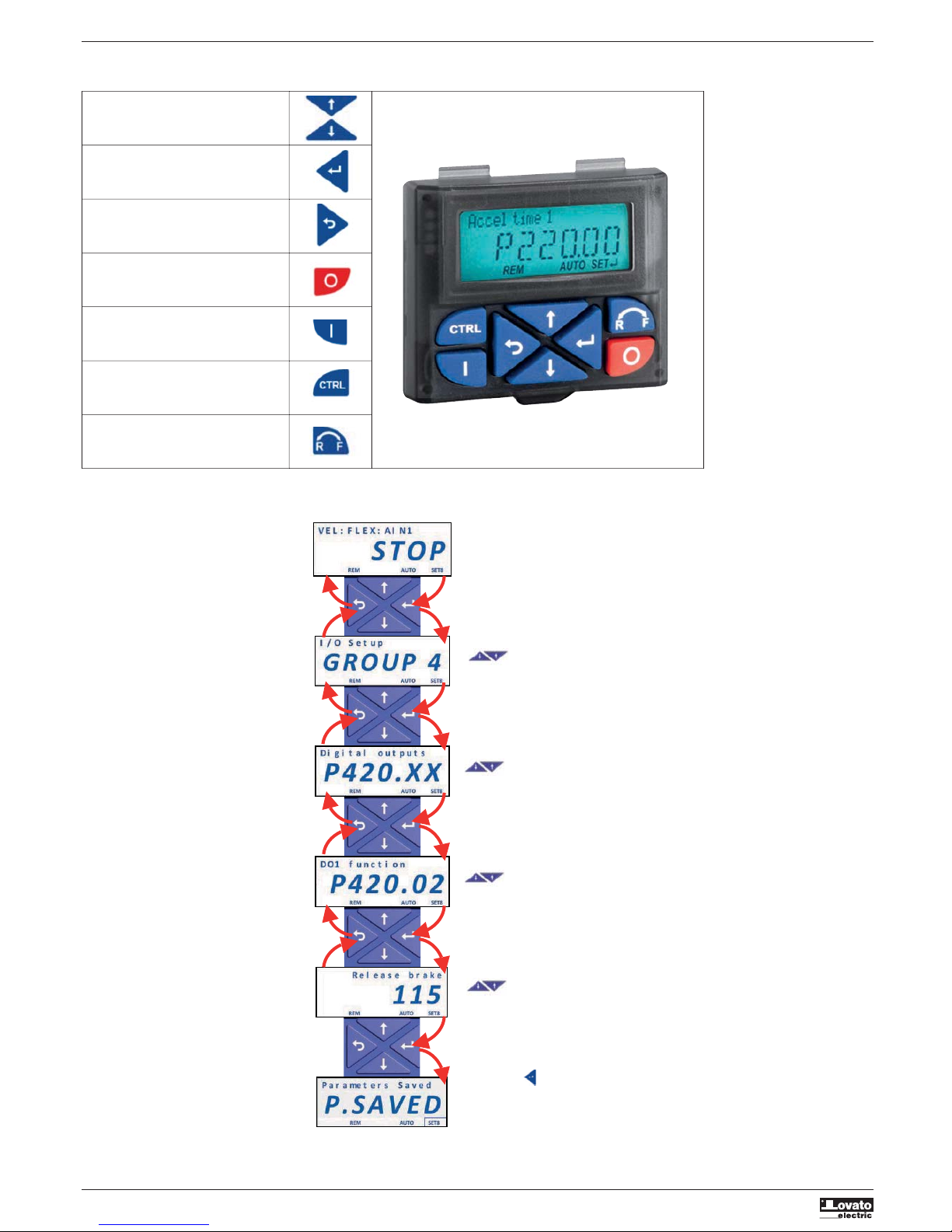
LEARN HOW TO NAVIGATE THE MEN
U
S
ee chapter 1
RESET PARAMETERS TO
D
EFAULT
S
ee cha
p
ter 2
CO
NFI
GU
RE ADDITI
O
NAL F
U
N
C
TI
O
N
S
See cha
p
ter 6
Steps to follow for the confi
g
uration of the variable speed drive:

I
586 GB 01 19
2
1. NAVI
G
ATI
O
N IN THE MEN
U
AND L
O
ADIN
G
DEFA
U
LT
S
ETTIN
GS
Function of the ke
y
pad ke
y
s
Navi
g
ate: select
g
roup/parameter.
Chan
g
e parameter settin
g
.
Pressed shortl
y
: enter in the sub parameter level.
Kee
p
p
ressed for more than 3 sec to save
p
arameter
settings in the memor
y.
Exit from the menu/parameter
Stop motor
Run motor
Activate full keypad control
Rever
s
al of rotation direction
Example of navigation in the menu of the VSD and modification of a parameter
.
B
ack to the previous level
B
ack to the previous leve
l
B
ack to the previous leve
l
B
ack to the previous leve
l
w
ithout savin
g
E
nter in
p
arametrisation mode
E
nter in the grou
p
C
onfirm the parameter to modif
y
C
onfirm the sub-parameter
C
onfirm the modif
y
Keep pressed for 3 seconds to save all
t
he
p
arameters modi
f
ied.
Select the group
S
elect the
p
arameter
Select the sub-
p
arameter
Modif
y
the value of the parameter

I
586 GB 01 19
3
2
. RE
S
ET PARAMETER
S
T
O
DEFA
U
L
T
To reset all the parameters to factor
y
settings follow this procedure
:
– Set the parameter P700.01 = 1
(
load default settings
)
– Press the button several times to exit from the programming menu until it appears the text STOP.
– Keep pressed the button for 3 seconds until it appears the text “P.SAVED”, which indicates the saving of the parameters.

I
586 GB 01 19
4
3
. COMMAND THE RUN
/
STOP OF THE MOTO
R
3.1 2-wires control from the flexible I
/
O terminal bloc
k
3.2 From ke
y
pad
Parameter Function Setting Description
P400.01 VSD enable 1 VSD always enabled (default setting)
P400.02 Run/stop command 11 Run/stop command from digital input DI1 (connected between terminals DI1-24V)
N
O
COM
N
C
G
N
D
AI
1
AI2
A
O1
10
V
24V
DI1
DI2
DI3
DI4
DI
5
DO1
G
N
D
Parameter Function Setting Description
P400.01 VSD enable 1 VSD always enabled (default setting)
P400.12 Keypad control 1 Activate keypad as control source
P400.02 Run/stop command 1 Constant true (run/stop command is managed by keypad)
S
tart
Sto
p
R
un/Sto
p

I
586 GB 01 19
5
4
. FRE
Q
UENCY ADJUSTMEN
T
4.1 From ke
y
pad
Increase the
f
requency
Decrease the
f
requency
Parameter Function Setting Description
P201.01 Frequency setpoint source 1 Frequency adjusted from keypad
P210.00 Minimum frequency 0Hz Insert the value of the minimum frequency
P211.00 Maximum frequency 50Hz Insert the value of the maximum frequency
P220.00 Acceleration time 5sec Insert the value of the acceleration time
P221.00 Deceleration time 5sec Insert the value of the deceleration time
4.2 From external potentiometer
Parameter Function Setting Description
P201.01 Frequency setpoint source 2 Frequency adjusted with analog input 1 (AI1)
P210.00 Minimum frequency 0Hz Insert the value of the minimum frequency
P211.00 Maximum frequency 50Hz Insert the value of the maximum frequency
P220.00 Acceleration time 5sec Insert the value of the acceleration time
P221.00 Deceleration time 5sec Insert the value of the deceleration time
P430.01 Analog input 1 (AI1) configuration 0 Analog signal type 0-10V
P430.02 Value of frequency when AI1 is at minimum 0Hz Frequency when AI1 is at minimum (AI1 = 0V)
P430.03 Value of frequency when AI1 is at maximum 50Hz Frequency when AI1 is at maximum (AI1 = 10V)
N
O
COM
NC
G
N
D
AI
1
AI2
A
O1
10
V
24V
DI1
DI
2
DI3
DI4
DI
5
DO1
G
N
D
Potentiometer
4.3 From analog input signal t
y
pe 0-10V
Parameter Function Setting Description
P201.01 Frequency setpoint source 2 Frequency adjusted with analog input 1 (AI1)
P210.00 Minimum frequency 0Hz Insert the value of the minimum frequency
P211.00 Maximum frequency 50Hz Insert the value of the maximum frequency
P220.00 Acceleration time 5sec Insert the value of the acceleration time
P221.00 Deceleration time 5sec Insert the value of the deceleration time
P430.01 Analog input 1 (AI1) configuration 0 Analog signal type 0-10V
P430.02 Value of frequency when AI1 is at minimum 0Hz Frequency when AI1 is at 0V
P430.03 Value of frequency when AI1 is at maximum 50Hz Frequency when AI1 is at 10V
N
O
COM
NC
G
N
D
AI
1
AI2
A
O1
10
V
24V
DI1
DI2
DI3
DI4
DI
5
D
O1
G
N
D
Analog signal
0
...10VD
C
+
–

I
586 GB 01 19
6
4.4 From analog input signal t
y
pe 4-20mA
Parameter Function Setting Description
P201.01 Frequency setpoint source 2 Frequency adjusted with analog input 1 (AI1)
P210.00 Minimum frequency 0Hz Insert the value of the minimum frequency
P211.00 Maximum frequency 50Hz Insert the value of the maximum frequency
P220.00 Acceleration time 5sec Insert the value of the acceleration time
P221.00 Deceleration time 5sec Insert the value of the deceleration time
P430.01 Analog input 1 (AI1) configuration 4 Analog signal type 4-20mA
P430.02 Value of frequency when AI1 is at minimum 0Hz Frequency when AI1 is at 4mA
P430.03 Value of frequency when AI1 is at maximum 50Hz Frequency when AI1 is at 20mA
NO
C
OM
NC
G
ND
AI1
AI2
A
O1
10
V
24V
DI1
DI2
DI3
DI
4
DI
5
DO
1
G
N
D
Analo
g
si
g
nal
4-2
0
mA
+
–
4.5 With preset frequency setpoints
Parameter Function Setting Description
P210.00 Minimum frequency 0Hz Insert the value of the minimum frequency
P211.00 Maximum frequency 50Hz Insert the value of the maximum frequency
P220.00 Acceleration time 5sec Insert the value of the acceleration time
P221.00 Deceleration time 5sec Insert the value of the deceleration time
P400.18 Preset frequency selection bit 0 14 DI4 is the bit 0 of preset frequency selection
P400.19 Preset frequency selection bit 1 15 DI5 is the bit 1 of preset frequency selection
P450.01 Preset frequency 1 20Hz Value of preset frequency 1 (DI4 closed)
P450.02 Preset frequency 2 45Hz Value of preset frequency 2 (DI5 closed)
P450.03 Preset frequency 3 50Hz Value of preset frequency 3 (DI4 and DI5 closed)
DI5 (bit 0) DI4 (bit 1) Preset frequency activated
Open Open No preset frequency activated. The frequency is adjusted by the source set in P201.01
Open Closed Preset frequency 1
Closed Open Preset frequency 2
Closed Closed Preset frequency 3
N
O
C
OM
NC
G
N
D
AI
1
AI2
A
O
1
10
V
24V
DI1
DI2
DI3
DI4
DI
5
DO
1
G
N
D
P
reset
f
requenc
y
s
election
B
it 0
P
reset
f
requenc
y
s
election
B
it
1
Selection table of
p
reset frequencies.
N
O
COM
N
C
G
N
D
AI1
AI
2
A
O1
1
0V
24V
DI1
DI
2
DI3
DI4
DI
5
DO1
GN
D
2-wire
s
en
s
or wit
h
output 4-20mA
s
upplied at 24VDC
+
–

I
586 GB 01 19
7
4.7 PID Control - Setpoint ad
j
usted with ke
y
pad and feedback signal t
y
pe 0-10V
Parameter Function Setting Description
P201.02 PID setpoint source 1 PID setpoint adjusted from keypad
P210.00 Minimum frequency 30Hz Insert the value of the minimum frequency
P211.00 Maximum frequency 50Hz Insert the value of the maximum frequency
P220.00 Acceleration time 5sec Insert the value of the acceleration time
P221.00 Deceleration time 5sec Insert the value of the deceleration time
P430.01 Analog input 1 (AI1) configuration 0 Analog signal type 0-10V
P600.01 PID enable 1 PID function enabled
P600.02 PID feedback source 1 PID feedback connected to analog input AI1
P610.01 PID sleep mode activation 1 PID sleep mode enabled. Sleep mode is activated when the frequency is less than
P
610.03 for a time lon
g
er than P610.05
P610.03 PID sleep mode: frequency treshold 35Hz See above
P610.05 PID sleep mode: delay time 5sec See above
4.8 PID Control - Setpoint adjusted with keypad and feedback signal type 4-20mA
Parameter Function Setting Description
P201.02 PID setpoint source 1 PID setpoint adjusted from keypad
P210.00 Minimum frequency 30Hz Insert the value of the minimum frequency
P211.00 Maximum frequency 50Hz Insert the value of the maximum frequency
P220.00 Acceleration time 5sec Insert the value of the acceleration time
P221.00 Deceleration time 5sec Insert the value of the deceleration time
P430.01 Analog input 1 (AI1) configuration 4 Analog signal type 4-20mA
P600.01 PID enable 1 PID function enabled
P600.02 PID feedback source 1 PID feedback connected to analog input AI1
P610.01 PID sleep mode activation 1 PID sleep mode enabled. Sleep mode is activated when the frequency is less than
P
610.03
f
or a time longer than P610.05
P610.03 PID sleep mode: frequency treshold 35Hz See above
P610.05 PID sleep mode: delay time 5sec See above
4.6 From motor potentiometer
(
MOP
)
If the motor potentiometer is active as setpoint source, the frequency setpoint can be changed via the triggers assigned to two input contacts configured with the functions "MOP UP"
(
increase frequency
)
and "MOP
DOWN" (decrease frequency).
Parameter Function Setting Description
P400.04 Reset fault function (default: DI2) 0 Disable the reset fault function
P400.13 Reverse rotation function (default: DI3) 0 Disable the reverse rotation function
P400.23 Motor potentiometr UP function 12 DI2 = MOP UP function
P400.24 Motor potentiometr DOWN function 13 DI3 = MOP DOWN function
P400.25 Enable motor potentiometer as setpoint 1 MOP is used as frequency setpoint
P413.00 Motor potentiometr starting mode 0 The last MOP value is used as initial value
N
O
COM
NC
G
N
D
AI
1
AI2
A
O1
10V
24
V
DI1
DI2
DI3
DI4
DI
5
D
O1
G
N
D
M
OP UP
M
OP DOWN

I
586 GB 01 19
8
5. M
O
T
O
R PARAMETER
S
Parameter Function Setting Description
P208.01 AC input voltage 0 (=230V) Insert the value of the supply voltage
P300.00 Motor control mode 6 V/f characteristic control, open loop
P302.00 V/f shape 0 Linear V/f (Applications: conveyor belts, …)
1
Quadratic V/f (Applications: pumps, fans, …)
P303.01 V/f Base voltage 230V Set the same value of the rated voltage of the motor (P320.07)
P303.02 V/f Base frequency 50Hz Set the same value of the rated frequency of the motor (P320.05)
P315.01 Slip compensation 5% Set the suggested value
P320.04 Rated speed of the motor _rpm Insert the rated speed of the motor
P320.05 Rated frequency of the motor __Hz Set the rated frequency of the motor
P320.06 Rated power of the motor __KW Set the rated power of the motor
P320.07 Rated voltage of the motor __V Set the rated voltage of the motor
P320.08 Rated cosphi of the motor __ Set the rated cosphi of the motor
P323.00 Rated current of the motor _A Insert the rated current of the motor.
S
ettin
g
this parameter, the motor thermic protection will be enabled.
N
OTE. If
y
ou need to enable the sensorless vector control set P300.00=4.
All the other parameters must be left to default settings
Parameter Function Setting Description
P327.04 Automatic motor data identification 1 1= Start automatic identification of the motor data.
Note. Durin
g
the procedure, the motor is ener
g
ized!
Automatic motor data identification
Following the settings of the rated motor parameters, the automatic identification of the motor data can be performed, which results in the best possible parameter settings.
P
recondition
s
–
T
he motor mu
s
t be cold.
– All rated motor data are known and set in the VLA1
(
see above table
)
.
–
T
he VLA1 is supplied (DC-bus voltage is available).
–
T
he VLA1 is enabled, error-free and in the "Read
y
to switch on" or "Switched on" device state.
–
T
he motor is stopped
(
no start enable
)
.
– No quick sto
p
is active.
P
r
ocedu
r
e
– Enable the automatic motor data identification:
S
et P327.04 = 1.
– Issue the start command to start the procedure.
As soon as the process has been started, the VLA1 characteristic and the motor equivalent circuit diagram data are automaticall
y
identified.
The procedure can take from some seconds to minutes. During and after the procedure, the LED "RDY"
(
blue
)
is permanently on. After completing, a renewed start command is required to start the motor.

I
586 GB 01 19
9
6. ADDITI
O
NAL F
U
N
C
TI
O
N
S
6.1 Configuration of the rela
y
output function
To configure the function of the relay output with changeover contact
(
terminals NO-COM-NC
)
is necessary to set the parameter P420.01.
6.2 Confi
g
uration of the DO1 di
g
ital output function
To configure the function of the digital output (terminals DO1-GND) is necessary to set the parameter P420.02.
Here below are li
s
ted the mo
s
t common function
s
.
Parameter Function Setting Description
P420.01 Relay output function 50 Function “running”: the relay switches when the output frequency of the VLA1 is
g
reater than 0.2Hz.
56 Function “error active”: the relay switches in case of active error.
70 Function “frequency threshold exceeded”: the relay switches when the output
f
requenc
y
o
f
the VLA1 is greater than the threshold set in P412.00.
78 Function “current limit reached”: the relay switches when the motor current is
g
reater or equal to the maximum threshold set in P324.00 (calculated as % o
f
the
m
otor rated current P323.00).
H
e
r
e
be
l
o
w
a
r
e
li
s
t
ed
th
e
m
os
t
co
mm
o
n f
u
n
c
ti
o
n
s
.
Parameter Function Setting Description
P420.02 DO1 digital output function 50 Function “running”: the DO1 output is activated when the output frequency of the
VLA1 is
g
reater than 0.2Hz.
56 Function “error active”: the DO1 output is activated in case of active error.
70 Function “frequency threshold exceeded”: the DO1 output is activated when the
output frequenc
y
of the VLA1 is greater than the threshold set in P412.00.
78 Function “current limit reached”: the DO1 output is activated when the motor
current is greater or equal to the maximum threshold set in P324.00 (calculated
as % of the motor rated current P323.00
)
.
N
O
C
OM
NC
G
N
D
AI1
AI
2
A
O1
10
V
24V
DI1
DI2
DI3
DI4
DI
5
DO1
GN
D
1
00
mA m
a
x
24VD
C
L
oa
d

I
586 GB 01 19
1
0
6.3 Configuration of the AO1 analog output function
To configure the function of the AO1 analog output (terminals AO1-GND) is necessary to set the following parameters
.
Parameter Function Setting Description
P440.01 AO1 analog output range 1 0…10VDC
2
0…5VDC
3
2…10VDC
4
4…20mA
5
0…20mA
P440.02 AO1 analog output function 1 Actual output frequency (resolution 0.1 Hz)
2
Actual frequency setpoint (resolution 0.1 Hz)
3
Input signal of analog input 1 (resolution 0.1 %)
4
Input signal of analog input 2 (resolution 0.1 %)
5
Actual motor current (resolution 0.1 A)
6
Actual output power (resolution 0.001 kW)
7
Actual torque value (resolution 0.1 %)
P440.03 Definition of the signal value that corresponds to the minimum value at AO1 0 Example: if the analog output is configured with range 4…20mA (P440.01=4),
analog output. P440.03 is the value of the signal which corresponds to AO1=4mA.
P440.04 Definition of the signal value that corresponds to the maximum value at AO1 1000 Example: if the analog output is configured with range 4…20mA (P440.01=4),
analog output. P440.04 is the value of the signal which corresponds to AO1=20mA.
Example: configure the AO1 analog output with range 0…10VDC correspondent to the output frequency range 0...50Hz.
Parameter Function Setting Description
P440.01 AO1 analog output range 1 0…10VDC
P440.02 AO1 analog output function 1 Actual output frequency (resolution 0.1 Hz)
P440.03 Definition of the signal value that corresponds to the minimum value at AO1 0 The AO1 will be 0V when the output frequency is 0.0Hz.
analog output.
P440.04 Definition of the signal value that corresponds to the maximum value at AO1 500 The AO1 will be 10V when the output frequency is 50.0Hz.
analog output.
6.4 Enable of the start at power-up function (auto-restart)
W
arning! The activation of this mode causes the automatic restart of the motor at the switching on of the mains voltage of VLA1 variable speed drive. Verif
y
that all the safet
y
requirements are met
.
Parameter Function Setting Description
P203.02 Start at power-up enable (AUTOSTART) 1 The motor is automatically started after switching on the mains voltage of VLA1.
R
equirements:
–
Th
e
VLA1 m
us
t
be
e
n
ab
l
ed
.
–
The “Run” function
(
P400.02
)
must be associated to a digital input DI and it
m
ust be maintained closed to allow the automatic restart o
f
the motor at the
p
ower on
.
P200.00 Control selection 0 The run/stop command are managed by flexible I/O.
P400.02 Run/stop command 11 Run/stop command from digital input DI1.
N
O
CO
M
N
C
G
N
D
AI
1
AI2
A
O
1
10V
24V
DI1
D
I2
DI3
D
I4
D
I
5
DO
1
G
N
D
R
un

I
586 GB 01 19
6.5 Command of digital inputs from PLC
6.6 Configuration of the automatic (PID) / manual (frequency regulation) mod
e
The purpose of this confi
g
uration is to mana
g
e with a di
g
ital input the switchin
g
between two operatin
g
mode
:
– Automatic mode (AUT): the variable speed drive works with an automatic PID control
– Manual mode
(
MAN
)
: the variable speed drive is manually regulated in frequency
.
In this example are used the followin
g
di
g
ital inputs:
Automatic mode (AUT)
In AUT mode the variable speed drive works with PID control, where the PID setpoint is set from ke
y
pad and the feedback is monitored from the AI1 analog input.
In this example we have assumed that on the AI1 analog input is connected a pressure sensor with output 0-10V, correspondent to a pressure of 0-15Bar with a linear characteristic, as shown in the followin
g
d
iagram.
This means that: if the output of the sensor is 0V it means a pressure of 0 Bar, if the output of the sensor is 10V it means a pressure of 15 Bar, if the output of the sensor is 5V it means a pressure of 7.5 Bar, and so
o
n.
In addition, in this exam
p
le we want to allow the user of the VLA1 to set a PID set
p
oint limited from 2 Bar to 8 Bar.
NO
CO
M
N
C
G
N
D
AI1
AI
2
A
O1
1
0V
24
V
DI1
DI
2
DI
3
DI4
DI
5
D
O
1
GN
D
R
un / Sto
p
AUT
/
MAN mod
e
s
e
l
ect
i
on
P
otentiometer
Sensor with
output 0...10VDC
+
–
Digital input Function
DI1 Command of the run/stop, independently from the selected mode (AUT/MAN).
DI2 Command the switching between the AUT and MAN mode: opened = AUT mode, closed = MAN mode.
1
1
Connection to PLC with dry contact output Connection to PLC with PNP output Connection to PLC with tensioned output 24VDC

I
586 GB 01 19
1
2
Manual mode
(
MAN
)
In MAN mode the PID control is de-activated and the variable speed drive works with manual regulation o
f
the
f
requency setpoint via a potentiometer connected to the AI2 analog input (type 0-10V).
In this example we con
f
igure the variable speed drive to provide an output
f
requency o
f
0Hz when the potentiometer is at minimum o
f
its regulation scale
(
0V
)
and a
f
requency o
f
50Hz when the potentiometer is at
maximum
(
10V
)
.
Example of use.
Once the parameters listed above have been set on the VLA1, test the functionin
g
:
–
Keep opened the DI2 digital input to allow the enable of the automatic mode (AUT).
–
With the buttons of the keypad set a PID setpoint, which for this specific example it corresponds to a pressure setpoint. For example, set a PID setpoint of 4.0 PID Unit (= 4 Bar).
–
The VLA1 read the value of the pressure of the plant
(
PID feedback
)
from the AI1 analog input, to which is connected the output of a pressure sensor. The 0- 10V voltage signal of the pressure sensor i
s
automatically transformed by the VLA1 in a pressure value according to the parameters previously set
(
in this example: 0V = 0 Bar, 10V = 15 Bar
)
.
–
Close the DI1 di
g
ital input to run the motor
.
–
If the pressure of the plant is lower than the setpoint
(
e.g. 2 Bar, which is lower than 4 Bar
)
the VLA1 increases the speed of the motor by regulating the output frequency until the PID setpoint is reached. In this
specific example, the output frequency of the drive when PID control is active is limited to the 20% and 80% of the maximum frequency
(
50Hz
)
, which means from 10Hz to 40Hz.
–
If you want to switch the operating mode to manual mode (MAN) close the DI2 digital input.
–
Now the PID control is de-activated
(
the value of AI1 signal is ignored
)
. The output frequency of the drive is adjusted with the external potentiometer, connected to the AI2 analog input. In this specific example, the
output frequenc
y
regulated with the potentiometer can be ad
j
usted from 0Hz to 50Hz.
–
To command the motor stop, open the DI1 digital input
.
Parameter Function Setting Description
P201.01 Frequency setpoint source 3 Frequency adjusted with analog input 2 (AI2)
P201.02 PID setpoint source 1 PID setpoint adjusted from keypad
P210.00 Minimum frequency 0 Hz Insert the value of the minimum frequency
P211.00 Maximum frequency 50 Hz Insert the value of the maximum frequency
P220.00 Acceleration time 5 sec Insert the value of the acceleration time
P221.00 Deceleration time 5 sec Insert the value of the deceleration time
I/O configuration
(
AI1 = PID feedback, AI2 = frequency setpoint, DI1 = run/stop, DI2 = AUT-MAN mode switch
)
P430.01 Analog input 1 (AI1) configuration 0 Analog signal type 0-10V
P430.04 PID value when AI1 is at minimum 0 Minimum value of AI1 signal expressed in PID Unit (0V = 0 PID unit, in this
e
xample correspondent to 0 Bar of pressure
)
P430.05 PID value when AI1 is at maximum 15 Maximum value of AI1 signal expressed in PID Unit (10V = 15 PID unit, in this
e
xample correspondent to 15 Bar of pressure)
P431.01 Analog input 2 (AI2) configuration 0 Analog signal type 0-10V
P431.02 Frequency value when AI2 is at minimum 0 Hz Insert the frequency value correspondent to AI2 signal at minimum (0V)
P431.03 Frequency value when AI2 is at maximum 50 Hz Insert the frequency value correspondent to AI2 signal at maximum (10V)
P400.02 Run/stop command 11 Run/stop command from digital input DI1
P400.45 Deactivate PID control 12 DI2 opened = PID enabled, provided that P600.01=1 (AUT mode)
D
I2 closed = PID disabled
(
MAN mode
)
Configuration of PID parameters
(
AUT mode
)
P600.01 PID enable 1 PID function enabled
P600.02 PID feedback source 1 PID feedback connected to analog input AI1
P600.05 Minimum PID operating frequency 20% Minimum value of the operating frequency of the PID control expressed as %
of the maximum frequency of the drive P211.00 (100% = P211.00 = 50Hz)
In this exam
p
le: 20% of 50Hz = 10Hz
P600.06 Maximum PID operating frequency 80% Maximum value of the operating frequency of the PID control expressed as %
of the maximum frequency of the drive P211.00
(
100% = P211.00 = 50Hz
)
In this example: 80% of 50Hz = 40Hz
P605.01 Minimum value of the PID setpoint 2 Minimum value of the settable PID setpoint, expressed in PID unit.
In this exam
p
le: 2 PID Unit, corres
p
ondent to 2 Bar of
p
ressure
.
P605.02 Maximum value of the PID setpoint 8 Maximum value of the settable PID setpoint, expressed in PID unit.
In this exam
p
le: 8 PID Unit, corres
p
ondent to 8 Bar of
p
ressure
.
P606.01 PID acceleration time 10 sec Insert the acceleration time of the PID control
P606.02 PID deceleration time 10 sec Insert the deceleration time of the PID control

I
586 GB 01 19
1
3
6.8
C
ommon error codes
Error code Description Possible causes Remedy
0x2350 Motor overload (i
2
*t) Motor thermally overloaded. Possible causes: – Check drive dimensioning.
–
Impermissible continuous current. – Check machine/driven mechanics for excessive load.
–
Too
f
requent acceleration processes.
–
Too long acceleration processes.
0x2320 Short circuit/earth leakage – Short circuit/earth fault of motor cable – Check motor cable.
–
Capacitive charging current of the motor cable too high. – Check length of the motor cable.
–
Use shorter or lower-capacitance motor cable.
0x2382 I*t error Device utilisation (I*t) too high by frequent and too long – Check drive dimensioning.
acceleration processes.
0x3210 DC bus overvoltage DC-bus voltage has exceeded the error threshold for – Reduce dynamic performance of the load profile.
overvoltage (display in parameter P208.06, results from the – Check mains voltage.
setting of the rated mains voltage in P208.01). – Check settings for the brake energy management
Possible causes: (see chapter Brake energy management on I585
–
Too high braking energy. instruction).
–
Too high mains voltage.
0x3220 DC bus undervoltage DC-bus voltage has fallen below the error threshold for – Check mains voltage.
undervoltage (display in parameter P208.03, results from – Check DC-bus voltage.
the setting of the rated mains voltage in P208.01). – Check mains settings (see P208.01).
0x4210 Power unit overtemperature The heatsink temperature of the power unit (display in – Provide for a sufficient cooling of the device.
P117.01) has exceeded the fixed error threshold 100°C. – Clean fan and ventilation slots.
Possible causes: – If required, replace fan.
–
Ambient temperature too high. – Reduce switching frequency in P305.00.
–
Fan or ventilation slots are
p
olluted.
–
Fan i
s
defective.
Other manuals for VLA1 series
1
Table of contents
Other LOVATO ELECTRIC DC Drive manuals
Popular DC Drive manuals by other brands

RHINO MOTION CONTROLS
RHINO MOTION CONTROLS RMCS-3001 Installation Manual and Datasheet

Lenze
Lenze L-force ERBM Series Mounting instructions

National Instruments
National Instruments NI MID-7602 USER GUIDE AND SPECIFICATIONS

ABB
ABB ACS880 Series manual

Lenze
Lenze L-Force LCU Series Mounting instructions

LG
LG LUM850T user manual