625
B 01 22 31100465
G
B
L
VAT
ELE
TRI
.P.A.
24020 GORLE
BERGAMO
ITALIA
IA DON E. MAZZA, 12
EL. 035 4282111
E-mail in
o
vato
lectric.com
e
www.
ovato
lectric.com
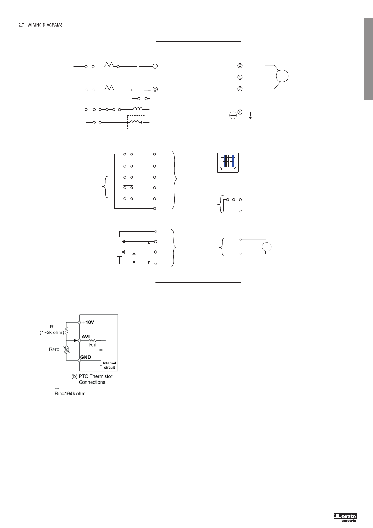
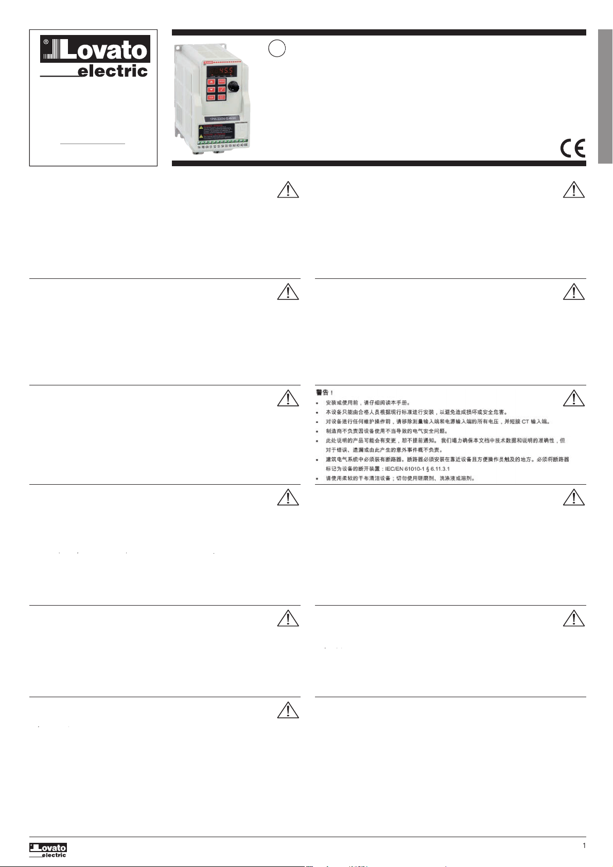
T1..
nstruct
on manua
ARNIN
!
arefull
read the manual before the installation or use
– This equipment is to be installed by quali
ied personnel, complying to current standards, to avoid
amages or sa
ety hazards.
– Before an
maintenance operation on the device, remove all the voltages from measuring and suppl
inputs and short
circuit the
T in
ut terminals
The manu
acturer cannot be held responsible
or electrical sa
ety in case o
improper use o
the equipment
ro
ucts
ustrate
ere
n are su
ect to a
terat
on an
c
anges w
t
out pr
or not
ce.
ec
n
ca
ata an
escr
pt
ons
the documentation are accurate, to the best of our knowled
e, but no liabilities for errors, omissions or contin
encie
risin
there from are accepted
A circuit breaker must be included in the electrical installation o
the building. It must be installed close by th
equipment and within easy reach o
the operator. It must be marked as the disconnecting device o
the equipment:
IE
/EN 61010-1
6.11.3.1
lean the device with a soft dr
cloth; do not use abrasives, liquid detergents or solvents.
ATTENZI
NE
e
ere attentamente
manua
e pr
ma
e
ut
zzo e
nsta
az
one
–
uesti apparecchi devono essere installati da personale qualificato, nel rispetto delle vigenti normative
mp
ant
st
c
e, a
o scopo
ev
tare
ann
a persone o cose.
–
r
ma
qua
s
as
ntervento su
o strumento, to
ere tens
one
a
n
ress
m
sura e
a
mentaz
one
cortocircuitare i tra
formatori di corrente
l costruttore non si assume res
onsabilit
in merito alla sicurezza elettrica in caso di utilizzo im
ro
rio del dis
ositivo
prodotti descritti in questo documento sono suscettibili in qualsiasi momento di evoluzioni o di modi
iche. L
escrizioni ed i dati a catalo
o non possono pertanto avere alcun valore contrattuale
Un interruttore o dis
iuntore va compreso nell’impianto elettrico dell’edificio. Esso deve trovarsi in stretta vicinanz
ell’apparecchio ed essere facilmente raggiungibile da parte dell’operatore. Deve essere marchiato come il dispositivo d
nterruzione dell’apparecchio: IE
/ EN 61010-1 § 6.11.3.1
u
re
apparecc
o con panno mor
o, non usare pro
ott
a
ras
v
,
eter
ent
qu
o so
vent
TTENTI
N
re attent
vement
e manue
avant toute ut
at
on et
n
ta
at
on.
–
es appareils doivent
tre install
s par un personnel qualifi
, conform
ment aux normes en vigueur en
ati
re d'installations, afin d'
viter de causer des dommages
des personnes ou choses
Avant toute intervention sur l'instrument
mettre les entr
es de mesure et d'alimentation hors tension et court-circuite
le
tran
formateur
de courant
– Le constructeur n'assume aucune responsabilit
quant
la s
curit
lectrique en cas d'utilisation impropre du
ispositi
es
roduits d
crits dans ce document sont susce
tibles d'
voluer ou de subir des modifications
n'im
orte que
oment. Les descriptions et caractéristiques techniques du catalo
ue ne peuvent donc avoir aucune valeu
contractue
e
Un interrupteur ou disjoncteur doit être inclus dans l'installation électrique du bâtiment. Celui-ci doit se trouver tou
près de l'appareil et l'opérateur doit pouvoir
accéder facilement. Il doit être marqué comme le dispositif d'interruptio
e l'appareil : IEC/ EN 61010-1
6.11.3.1
ettoyer l’appareil avec un chiffon doux, ne pas utiliser de produits abrasifs, d
tergents liquides ou solvants
UWA
A
–
rzed uż
ciem i instalac
ą urządzenia należ
uważnie przecz
tać ninie
szą instrukc
ę.
– W celu uniknięcia obraże
os
b lub uszkodzenia mienia te
o t
pu urządzenia muszą b
instalowane przez
ykwali
ikowany personel, zgodnie z obowiązującymi przepisami
–
rzed rozpoczęciem
akichkolwiek prac na urządzeniu należ
odłącz
ć napięcie od we
ść pomiarow
ch i zasilania oraz zewrzeć
ac
s
prze
a
n
a prą
owe
o.
– Producent nie prz
mu
e na siebie odpowiedzialno
ci za bezpiecze
stwo elektr
czne w prz
padku niewła
ciwe
o uż
tkowania
rzą
zen
a.
–
rodukt
opisane w ninie
sz
m dokumencie mo
ą b
ć w każde
chwili udoskonalone lub zmod
fikowane. Opis
oraz dane
atalo
owe nie mo
ą mieć w związku z t
m żadne
wartości umowne
.
–
instalac
i elektr
czne
bud
nku należ
uwz
lędni
przełącznik lub w
łącznik automat
czn
. Powinien on zna
dowa
się
bliskim sąsiedztwie urządzenia i by
łatwo osiągalny przez operatora. Musi by
oznaczony jako urządzenie służące do wyłączania
rządzenia: IEC/ EN 61010-1
6.11.3.1.
– Urządzenie należ
cz
ścić miękką szmatką, nie stosować środkow ściern
ch, pł
nn
ch deter
entow lub rozpuszczalnikow.
HTUN
Dieses Handbuch vor
ebrauch und Installation aufmerksam lesen.
Zur Vermeidung von Personen- und Sachschäden dürfen diese Geräte nur von qualifiziertem
Fachpersonal und unter Befol
un
der einschlä
i
en Vorschriften installiert werden
Vor
edem Eingriff am Instrument die Spannungszufuhr zu den Messeingängen trennen und die Stromwandle
urz
c
– Bei zweckwidrigem Gebrauch der Vorrichtung übernimmt der Hersteller keine Haftung für die elektrische Sicherheit
– Die in dieser Broschüre beschriebenen Produkte können
ederzeit weiterentwickelt und geändert werden. Die im Katalog
enthaltenen Beschreibun
en und Daten sind daher unverbindlich und ohne
ewähr
n die elektrische Anlage des
ebäudes ist ein Ausschalter oder Trennschalter einzubauen. Dieser muss sich i
nmittelbarer Nähe des
eräts befinden und vom Bediener leicht zugänglich sein. Er muss als Trennvorrichtung für da
erät gekennzeichnet sein: IE
/ EN 61010-1
6.11.3.1
as
erät mit einem weichen Tuch reini
en, keine
cheuermittel, Flüssi
reini
er oder Lösun
smittel verwenden
DVERTEN
IA
eer atentamente e
manua
antes
e
nsta
ar
ut
zar e
regu
a
or.
Este dis
ositivo debe ser instalado
or
ersonal cualificado conforme a la normativa de instalaci
n
vigente a
in de evitar daños personales o materiales
Antes de realizar cualquier operaci
n en el dispositivo, desconectar la corriente de las entradas de alimentaci
n
edida,
cortocircuitar los transformadores de corriente.
El fabricante no se responsabilizar
de la se
uridad el
ctrica en caso de que el dispositivo no se utilice de form
ecua
a.
os productos descritos en este documento se pueden actualizar o modi
icar en cualquier momento. Por consiguiente
las descripciones y los datos técnicos aquí contenidos no tienen valor contractual.
La instalación eléctrica del edificio debe disponer de un interruptor o disyuntor. Éste debe encontrarse cerca del
ispositivo, en un lugar al que el usuario pueda acceder con facilidad. Adem
s, debe llevar el mismo marcado que e
interruptor del dispositivo (IE
/ EN 61010-1 § 6.11.3.1)
–
impiar el dispositivo con un trapo suave; no utilizar productos abrasivos, deter
entes líquidos ni disolventes
РЕ
УПРЕЖ
ЕНИЕ!
–
режде чем прист
пать к монтаж
или экспл
атации
стройства, внимательно ознакомьтесь с одержанием
т
ящ
г
к
в
д
тв
–
о избежание травм или материального
щерба монтаж должен с
ществляться только квалифицированным персоналом
соответствии с де
ствующими нормативами.
–
еред проведением любых работ по техническом
обсл
живанию
стройства необходимо обесточить все измерительные
питающие входные контакты, а также замкн
ть накоротко входные контакты трансформатора тока
ТТ
–
роизводитель не несет ответственность за обеспечение электробезопасности в сл
чае ненадлежащего использовани
стро
ства.
–
зделия, описанные в настоящем док
менте, в любой момент мог
т подвергн
ться изменениям или
совершенствованиям.
оэтом
каталожные данные и описания не мог
т рассматриваться как действительные с точк
ния к
нт
кт
лектрическая сеть здания должна
ыть оснащена автоматическим выключателем, который должен
ыть расположен
близи обор
дования в пределах дост
па оператора. Автоматический выключатель должен быть промаркирован как
тключающее
стройство обор
дования: IEC /EN 61010-1
6.11.3.1.
–
чистк
стройства производить с помощью мягкой с
хой ткани, без применения абразивных материалов, жидких
моющих средств или растворителе
P
Z
RNĚN
– Návod se pozorně pročtěte, než začnete re
ulátor instalovat a používat.
–
ato zařízení smí instalovat kvali
ikovaní pracovníci v souladu s platn
mi předpis
a normami pro předcházení
úraz
osob či poškození věcí.
–
řed
ak
mkoli zásahem do přístro
e odpo
te měřicí a napá
ecí vstup
od napětí a zkratu
te transformátor
proudu.
–
robce nenese odpovědnost za elektrickou bezpečnost v případě nevhodného používání re
ulátoru
–
robk
popsan
v tomto dokumentu mohou kd
koli pro
t
pravami
i dal
m v
vo
em. Popis
a
da
e uveden
v katalo
u nema
roto žádnou smluvní hodnotu
Spínač či odpo
ovač
e nutno zabudovat do elektrického rozvodu v budově. Muse
í b
t nainstalované v těsné blízkosti přístro
e
snadno dostupné pracovníku obsluh
. Je nutno ho označit
ako v
pínací zařízení přístro
e: IE
EN 61010-1
6.11.3.1
P
stro
ist
te m
kkou ut
rkou, nepou
ve
te abrazivn
produkt
, tekut
istidla
i rozpou
t
dla
İKKAT
–
onta
ve kullanımdan önce bu el kitabını dikkatlice oku
unuz.
–
u aparatlar kişilere ve
a nesnelere zarar verme ihtimaline karşı
r
rl
kte olan sistem kurma normlarına
re
ali
iye personel tara
ından monte edilmelidirler
–
parata
cihaz
herhan
i bir müdahalede bulunmadan önce ölçüm
irişlerindeki
erilimi kesip akım transformatörlerinede kısa
–
Üretici aparatın hatalı kullanımından kaynaklanan elektriksel güvenliğe ait sorumluluk kabul etmez.
–
u dokümanda tarif edilen ürünler her an evrimlere ve
a de
işimlere açıktır. Bu sebeple katalo
daki tarif ve de
erler herhan
i
i
a
a
ıcı
e
er
a
z
e
r.
–
inanın elektrik sisteminde bir anahtar ve
a şalter bulunmalıdır. Bu anahtar ve
a şalter operat
r
n kola
lıkla ulaşabilece
i
a
ı
bir
erde olmalıdır. Aparatı
cihaz
devreden çıkartma
örevi
apan bu anahtar ve
a şalterin markası: IE
EN 61010-1
6.11.3.
–
paratı
cihaz
sıvı deter
an ve
a solvent kullanarak
umuşak bir bez ile siliniz aşındırıcı temizlik ürünleri kullanma
ınız.
AVERTIZARE!
–
itiţi cu atenţie manualul înainte de instalare sau utilizare.
– Acest echipament va
i instalat de personal cali
icat, în con
ormitate cu standardele actuale, pentru a evita
eter
orăr
sau
er
co
e
e.
Înainte de efectuarea oricărei operaţiuni de întreţinere asupra dispozitivului, îndepărtaţi toate tensiunile de la intrările de
mă
urar
şi de alimentare şi scurtcircuitaţi bornele de intrare
T
Producătorul nu poate
i considerat responsabil pentru si
uranţa electrică în caz de utilizare incorectă a echipamentului
Produsele ilustrate în prezentul sunt supuse modificărilor
i schimbărilor fără notificare anterioară. Datele tehnice
i descr
ril
i
documentaţie sunt precise, în măsura cunoştinţelor noastre, dar nu se acceptă nicio răspundere pentru erorile, omiterile sau
even
mente
e neprevăzute care apar ca urmare a acestora
Trebuie inclus un dis
unctor
n instalaţia electrică a clădirii. Acesta trebuie instalat aproape de echipament şi
ntr-o zonă
accesibilă operatorului. Acesta trebuie marcat ca fiind dispozitivul de deconectare al echipamentului: IEC/EN 61010-1
6.11.3
1
– Curăţaţi instrumentul cu un material textil moale şi uscat; nu utilizaţi substanţe abrazive, deter
enţi lichizi sau solvenţi