Loveshaw Little David LD24 User manual

Little David™ Case Sealer
LD24 Uniform Side Belt Drive
Fully Automatic Case Sealer
Version: 10/10/11 Rev A
Operator’s Manual

i
LITTLE DAVID™ CASE SEALER
LD24 Operation
Copyright Loveshaw
Loveshaw, Inc.
2206 Easton Turnpike, PO. Box 83
South Canaan, PA 18459
Tel: 1-800-962-2633 • 570-937-4921
Fax: 570-937-4016
www.loveshaw.com
ITW PADLOCKER, LTD.
Unit 9 Brunel Gate
West Portway Industrial Estate
Andover, Hampshire SP10 3SL
ENGLAND
Tel: 264-357511
Fax: 264-355964
Monday, October 10, 2011


Table of Contents
Chapter1:Introduction 1
Chapter 2: Operating Safety 2
Chapter 3: Overview & Setup 7
Chapter 4: Installation 13
Chapter 5: Theory of Operation 15
Chapter 6: Machine Components 20
Chapter 7: Maintenance 29

ii
Chapter 8: Troubleshooting 38
Chapter 9: Warranty 40
Chapter 10: Assembly Drawings and Schematic 42

1
Introduction
hank you for purchasing the Little David™ case sealer, the LD24.
The LD24 is a fully-automatic side belt drive case sealer. The
LD24 is a robust built 24/7 case sealer constructed of quality
materials, robust drive motors, pneumatic and electrical
components.. All employees who will be required to operate and maintain the
case sealer must read this manual to ensure safe operation as well as proper
set-up and maintenance throughout the life of the machine. After reading
this manual, you will know how to perform the following functions,
How to operate the machine safely.
How to set the conveyor height of the machine
How to set up and change over to different box sizes.
How to set the machine to operate in automatic mode.
How disable energy saving mode.
How to adjust the pneumatic controls.
How to adjust the moveable photoelectric sensors.
Troubleshooting and replacing of worn or defective parts.
Throughout this manual there are several illustrations designed to help
perform the variety of tasks described.
Chapter
1
T

2
Operating Safety
Observe the warnings and cautions below when using the Little David LD24 case sealer.
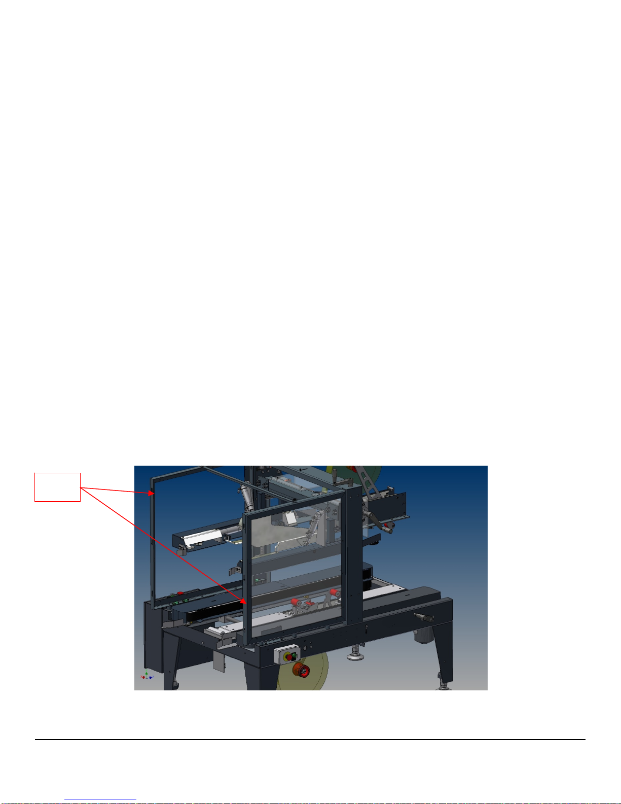
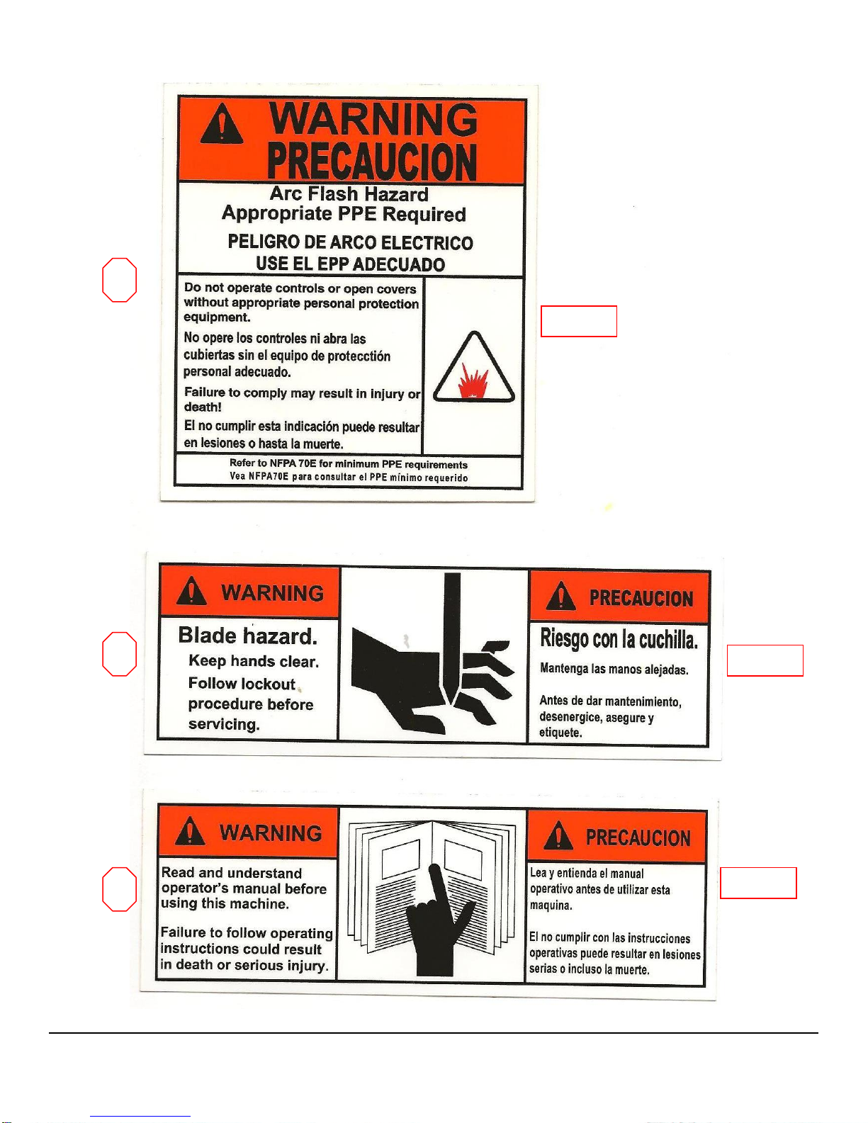
Within this manual on pages 4 -6, all safety labels are depicted with location and part
number. If a safety, label is missing or not legible it must be replaced immediately.
Failure to follow safety labels can lead to injury or damage to the machine.
Instruction: Requirement to System Operation
An electrical receptacle must be located near the machine. The line cord
connection to the receptacle is the disconnect means for the machine. The
receptacle must be located in an area that is easily accessible to all personnel.
Warning: Potential Bodily Injury
Always disconnect all sources of energy to the machine before performing maintenance.
Sources of energy include electrical and pneumatic. Refer to your company’s lock out
tag out procedures.
Never bypass or remove safety guards from the machine or tape cartridge.
Never override safety devices such as Emergency Stop switches.
Never adjust the machine or tape cartridges when the machine is operating.
Never place hands or body inside confines of the machine unless top head assembly is
locked in place and all power sources are locked out.
Never wear jewelry, loose clothing, such as ties, scarves etc and long hair must be pulled
back when operating this machine.
Never pull a jammed box out of the machine while it is in operation. Stop machine and
open the side drives and raise the head assembly.
When feeding a box into the machine manually avoid the rear flap folding mechanisms.
Chapter
2
Instruction:
W
arning:
Warning:
Warning:
Warning:
Warning:
Warning:
Warning:
Warning:

3
This manual contains operator information for Little David Case Sealer Equipment. It is directed toward the person who
operates and maintains the machine. Read through the manual completely before operating the machine. Thereafter,
refer to it as necessary.
Take special note of all warnings, cautions, and maintenance instructions. Like any other piece of equipment, the Little
David Case Sealer functions best when maintained and used correctly.
Caution: Potential Machine Damage:
Never push or drag machine across the floor with the top head assembly fully raised.
Makes sure it is completely lowered.
Never pull the machine by the guards or side belt drives.
Provide and use proper electrical power.
Do not operate, maintain, or otherwise use this machine, except as described in this
manual.
Special instruction:
The case sealer incorporates removable side guards that allow access to the flap folder section of the machinery for
maintenance convenience. Never operate the machine with these guards removed. Always use OSHA lock out / tag out
procedures before servicing this or any machinery.
Caution:
Caution:
Caution:
Caution:
SAFETY
GATES

4
1
2 3 5
2
4
4
6
4

5
1
2
3 SL-0002
SL-0021
SL-0001

6
4
5
6
SL-0003
SL-0006
SL-0004

SID
E
ASS
E
UPPE
R
GUID
E
MAJO
R
S
Q
UE
E
C
O
T
d
E
BELT
E
MBL
Y
HEAD
ASSEMBL
Y
R
BOX
E
R
FLAP
E
ZERS
C
ase
S
O
vervie
w
T
his manu
a
d
iagram ide
n
MINOR
SUPPR
E
PNEUMATIC
MAIN SHUT O
F
S
eale
w
a
l covers se
v
n
tifies the
k
FLAPS
E
SSO
R
F
F
MAIN ELEC
T
ENCLOSURE
7
r Sec
t
v
eral parts
k
ey section
s
T
RICAL
LOWE
R
GUIDE
S
t
ion
s
of the ma
c
s
of the ma
c
R
BOX
S
c
hine. The
c
hine.
M
A
F
O
following
Cha
p
3
I
G
A
JOR FLAPS
O
LDERS
p
ter
3
I
NDEXING
G
ATE
REAR FLAP
FOLDERS

8
Machine Specifications
Machine dimensions:
Height: 62” @ 22 ¼” conveyor height
Length:
64 ¾” overall including box guides.
58” overall frame length (Conveyor opening
dimension)
Width: 49” main electrical enclosure to opposite side
crank handle.
Conveyor height: 22 ¼” to 30 ¼” – Standard
Electrical Requirements:
Standard Voltage: 120/1/60 with 15 amp dedicated
service.
Optional voltages are available consult factory.

9
Operating speed:
Standard belt speed: 100 ft/min
Air Requirement:
5 scfm @ 80 psi
Machine box capacity:
Length: - 8” to 24”
Width: - 6” to 18”
Height: 4” to 18”
Machine Setup:
The following steps describe how to set up and change
the machine over from one size to another.
1. Insure that the machine is in Emergency Stop
mode.
2. Measure the box height and width. Measure the
box height with the all the flaps folded. This
measurement is critical and it is the outside
dimensions of the box.
Never
rely on the
measurements that maybe listed on the box itself,

10
these measurements are usually the inside
dimensions of the box.
3. Adjust the height assembly of the head to the
measured heighted of the box to be processed.
There is a crank handle on the top of the machine
to raise or lower the head assembly. There are
scales on the main upright structure of the
machine with an integral pointer and a scale.
4. Set the width of the top flap folder assembly and
side belt drive motors. This is accomplished by
using the crank handles supplied on both
adjusting lead screws. There are integral scales
and pointers on each adjustment.
5. Set the position of the minor flaps suppressor.
The position of the flap suppressor is dictated by
the width of the box. Loosen the locking handle
located at the in feed of the machine on the center
of the top head assembly. Slide the suppressor
until the scale located on the top of the suppressor
is at the width of the box to be processed. The
leading edge of the suppressor mounting bracket
is the indicating pointer for the scale.
6. Start the machine and try processing one box. If
the box does not properly fold flaps first check all
the settings made for the box, do not adjust any air
pressures or photoelectric sensor positions. Make
sure that the contents in the box itself do not
exceed the height of the score lines of the box.
Make sure that the minor and major flaps are not
interfering with each other. Insure that the major
flaps do not overlap.

11
SIDE BELTS DRIVE
WIDTH ADJUSTING
POINTER AND SCALE
HEAD HEIGHT
ADJUSTING
CRANK HANDLE
HEAD HEIGHT
POINTER AND
SCALE
FLAP FOLDER
WIDTH
POINTER AND
SCALE
FLAP FOLDER
WIDTH ADJUSTING
CRANK HANDLE
SIDE BELTS DRIVE
WIDTH ADJUSTING
CRANK HANDLE

12
MINOR FLAP SUPPRESSOR
SLIDE ADJUSTOR
LOCKING HANDLE
MINOR FLAPS
SUPPRESSOR POINER
AND SCALE

13
Installation
lways check for any signs that the machine may have been damaged
before fully removing it from the shipping skid. If the machine
arrives damaged contact Loveshaw immediately to help in filing a
claim with the shipping company.
Section 1: Placing the Machine
The case sealer is fully assembled and ready for operation.
Step One: Carefully remove the machine from the shipping skid.
Remove all fasteners and brackets holding the machine to the skid. Remove
head assembly hold down strapping and support materials.
Step Two: Take care removing the machine from the skid as it
weighs 800 pounds! Use a forklift or similar device to complete this task
Step Three: Move machine to the designate location. It may
be necessary to adjust the conveyor height of the machine. The legs on
the machine are adjustable by loosening the jam nuts on the threaded rod
and turning the nuts until the desired height is achieved. (Refer to figure
on page 7)
Step Four: Connect the utilities to the machine, compressed
air and electricity.
Chapter
4
A

14
LEVELLING PAD
JAM NUTS
THREADED
RODS

15
Theory of Operation
LD24
The LD24 will automatically fold all four top flaps and apply tape
to the top and bottom of corrugated cardboard boxes. The
LD24 provides indexing which maintains proper spacing between
boxes that are being processed by the machine.
With the machine started, a box either fed by powered conveyor
or hand enters the machine. The entrance photoelectric sensor
“PE1” detects the leading edge of the box and the programmable
logic controller (PLC) signals the in feed indexing gate to rise,
energizing solenoid valve “SV4”. Raising the in feed indexing
gate stops any other boxes from entering the machine until the
previous box has exited the folding section of the machine.
When the box enters the machine two side belts, one on each side
contacts the box and pulls it forward through the machine. The
box will travel past “PE1” signaling the plc to energize solenoid
valve “SV2” folding the rear minor flap downward towards the
exit end of the machine, simultaneously the front leading minor
flap is folded downward by the suppressor. As the box moves
forward through the machine the front leading flap will contact
the stationary suppressor and the flap will be plowed down. The
box will continue through the machine until photoelectric sensor
“PE2” becomes unblocked, signaling solenoid valve “SV3” to
energize folding the two major flaps downward while de-
energizing “SV2” resetting the rear minor flap folder. The box
will continue forward until the box travels under and over the
tape cartridges while the top major flaps are butted together by
squeezer rollers. Photoelectric sensor “PE3” will be unblocked
Chapter
5
Table of contents
Other Loveshaw Food Saver manuals