Low Noise Factory LNF-PBA User manual

Rev:2019-08-27
Manual for
LNF-PBA
Low Noise Power Block

Table of Contents
Contents
1. Introduction ............................................................................................................3
2. Specifications..........................................................................................................3
3. Safety information ..................................................................................................4
4. Installation ..............................................................................................................5
5. Mains voltage and fusing........................................................................................6
6. Using the instrument...............................................................................................7
7. Maintenance and service ........................................................................................8
8. Pinout......................................................................................................................9

P a g e | 3
1. Introduction
The LNF-PBA is a ±12V low noise linear power supply designed to power LNF’s line of HEMT
power supplies. It accepts a mains voltage of either 115 or 230 VAC selectable on the rear
panel. The front panel has 8 output connectors, all delivering the ±12 VDC.
2. Specifications
Input
Parameter
Description
Minimum
Nominal
Maximum
Unit
AC Input voltage range
Voltage selector at 115V
Voltage selector at 230V
104
209
115
230
132
264
VAC
AC Input Power
Voltage selector at 115V
Voltage selector at 230V
100
100
W
Input Frequency
AC input frequency
47
63
Hz
Output
Parameter
Description/Conditions
Minimum
Nominal
Maximum
Unit
Efficiency
55
%
Noise
Ripple and noise
2
3
mVPK-PK
Maximum Output
Current
+12V
-12V
1.7
1.7
A
Load Regulation
Output change for 50%
load change
-0.05
0.05
%
Environmental
Parameter
Description/Conditions
Minimum
Nominal
Maximum
Unit
Storage Temperature
-40
85
oC
Operating Temperature
5
40
oC
Relative Humidity1
Non-Condensing
5
80
%RH
1The LNF-PBA is for indoor use only, pollution degree 2.
Safety
IEC 61010-1:2010 3rd edition
Electromagnetic compatibility
Compliant with EMC directive IEC 61326-1:2012
Physical
Dimensions: 256 (W) x 98 (H) x 156 (D) millimeters
Weight: 3.21 kg

P a g e | 4
3. Safety information
After unpacking, make a visual inspection that there’s no damage to the unit. If any damage
is found, please contact the factory prior to taking it into operation.
Before first use, make sure the mains voltage selector is set in the correct position.
Readout of current
load from +12V
8x ±12VDC output connectors
Mains voltage indicator
Mains switch
AC inlet
Earth and Common access

P a g e | 5
4. Installation
The instrument must be installed in a flat and solid surface with at least 5cm of clearance on
the topside and right side where the air-intake and outlet are located.
The connection to the mains must be done with a cord compatible with IEC 60320-C14 with
an earth prong. The instrument must be connected to an outlet with earth.

P a g e | 6
5. Mains voltage and fusing
The instrument can be used with either 115 or 230 V mains voltage. The mains voltage is
selected on the rear panel. It is preconfigured to the voltage of your country when you
receive the instrument. Should you have to change it you need to follow the below
procedures
1. Disconnect the power cable from the instrument.
2. Open the hatch for the fuse assembly with a slot screwdriver. See photo below for
details.
3. Use a slot screwdriver to carefully pry out the red fuse assembly.
4. Replace both fuses according to the markings on the instrument. For 230 V use 0.5A
slow blow fuse and for 115 V use 1A slow blow. The fuse size is ¼” x 1-¼“.
5. Rotate the fuse assembly 180 degrees and reinsert it into the power entry module.
6. Close the hatch.
7. Double check that the mains voltage indicator shows the right voltage.
Fuse assembly hatch
Fuse assembly

P a g e | 7
6. Using the instrument
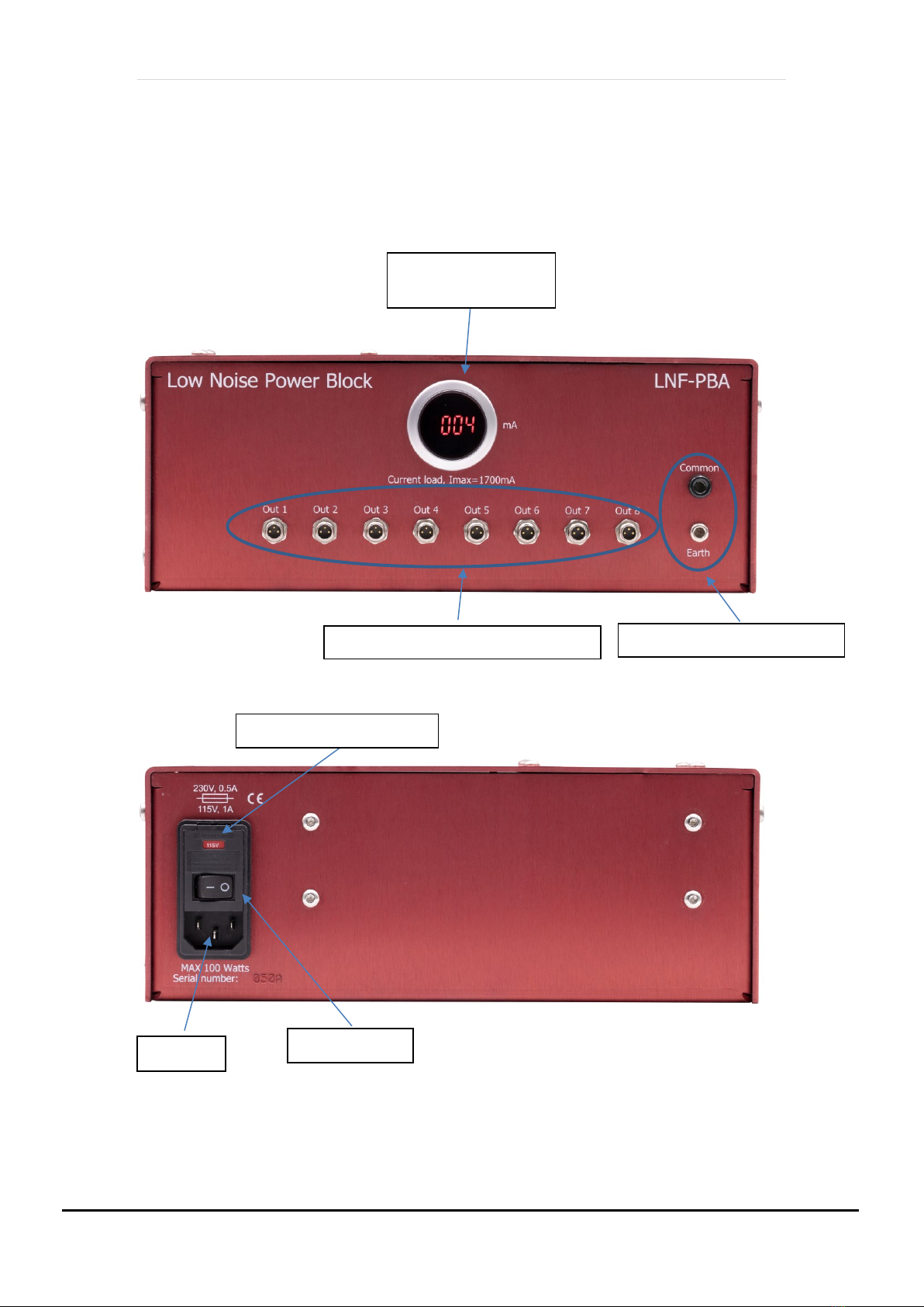
The LNF-PBA uses a transformer, rectifiers and regulators to convert mains AC to ±12V DC
needed for LNF’s HEMT power supplies. There are 8 identical output connectors on the front
panel providing the ±12V to the HEMT power supplies. All 8 outputs are connected in
parallel and are not isolated from each other. There’s a panel instrument on the front panel
indicating how much current is drawn from the +12V rail. Since all LNF’s current and future
HEMT power supplies mainly draw current from the positive rail, this current will always be
the limiting factor to how many power supplies the LNF-PBA can drive. The maximum
current the instrument can deliver is 1700 mA. The instrument has automatic current
limit/foldback. When the current exceeds 1700 mA, the voltage will drop below 12V. When
this happens all HEMT power supplies connected to the instrument will be affected and will
not operate properly. The table below lists typical current draw from LNF’s HEMT power
supplies. It is important to place the instrument so that the panel meter can easily be read
and the mains switch can easily be reached. Only use the supplied cable to connect the
instrument to LNF’s power supply or the accessory cable LNF-PBA-C.
Power supply model
+12V current at Ids=0 mA
+12V current at maximum Ids
LNF-PS_3
70 mA
120 mA
LNF-PS3b
70 mA
150 mA
LNF-PS_EU2
35 mA
235 mA
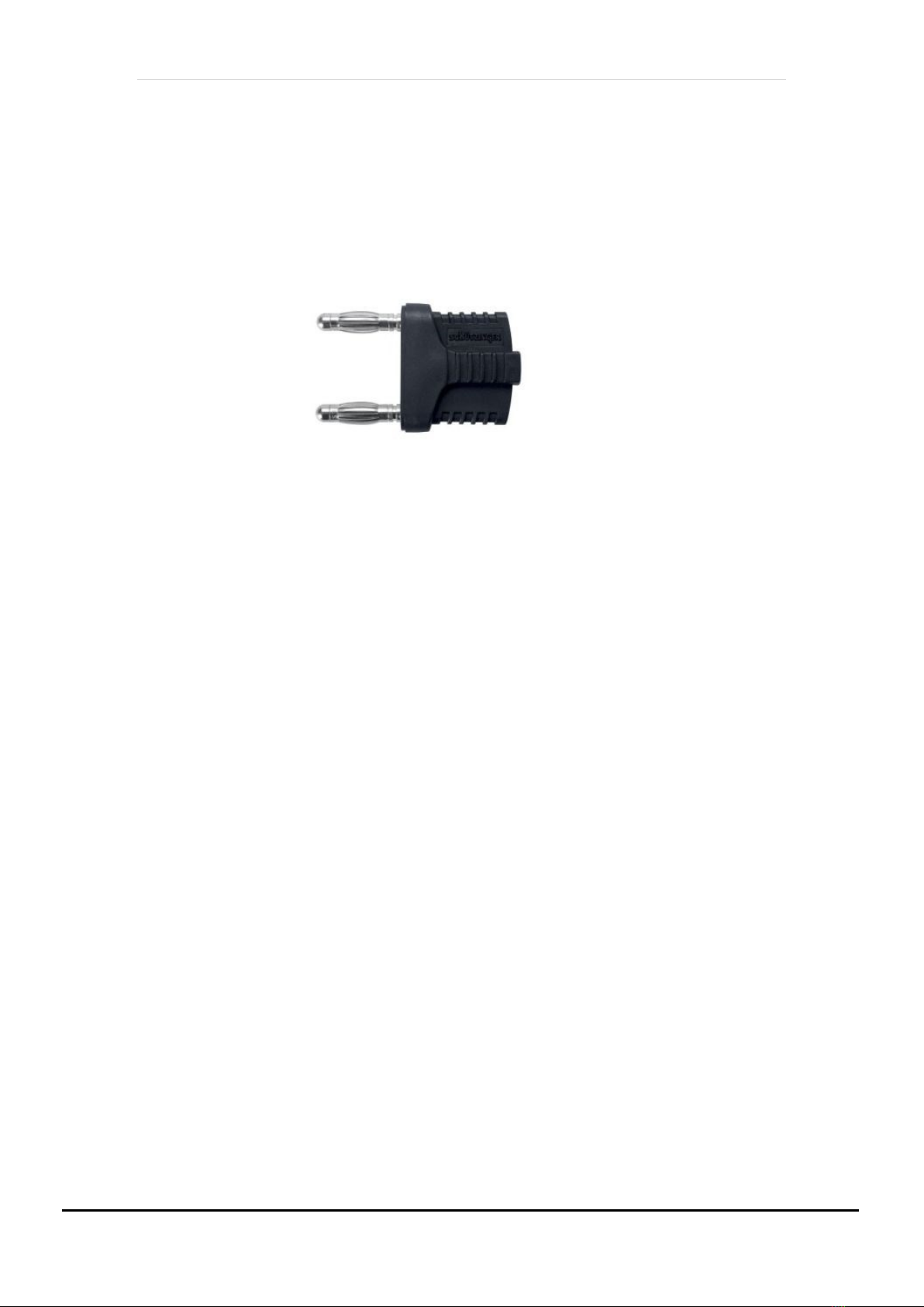
There’s access to circuit common and earth on the instrument’s front panel. There’s also a
jumper plug included with the instrument which can be used to connect circuit common to
earth. With this feature, the instrument can be configured to be floating or non-floating. It is
highly recommended to always use it non-floating, i.e. with the jumper plug installed, when
connecting or disconnecting LNAs to your system. Once the system is in operation, the
jumper plug can be removed if a floating system is desired. This could be the case in complex
Fuses

P a g e | 8
electrical systems with many ground return paths to prevent ground loops. If there’s no
specific reason to use it floating, it is recommended to always leave the jumper plug
installed. In floating operation, the instrument common can float several Volts over earth
(depending on your lab’s electrical system) which could cause LNA failures when connecting
or disconnecting an LNA if the Vd or Vg pin engages before the ground pin. It is therefore
important to always use the jumper plug when connecting or disconnecting LNAs.
Jumper plug
7. Maintenance and service
There are no serviceable parts in the instrument. If the ventilation holes are clogged with
dust, disconnect the instrument from the mains supply and use a dry cloth to gently clear
the ventilation holes.

P a g e | 9
8. Pinout
3-Pin male M8 connector seen from outside LNF-PBA chassis
GND
+12V
-12V
Other manuals for LNF-PBA
1
Table of contents
Other Low Noise Factory Power Supply manuals