LOXONE 200001 User manual

INSTRUCTION MANUAL
200001, 200002, 200143
Instruction Manual
BEFORE USING THE POWER SUPPLY UNIT
Pay attention to all warnings and cautions before using the unit. Incorrect usage could lead to
an electrical shock,
damage to the unit or a fire hazard.
Warning Symbols
CAUTION
. DO NOT MODIFY, DISASSEMBLE THE POWER SUPPLY.
. READ INSTRUCTION MANUAL BEFORE CONNECTING TO MAINS.
. ELECTRIC SHOCK HAZARDOUS ON THE CONNECTOR SECTION.
NOTICE:
Installing/Storage Environment
1. Store the product with ambient temperature –40 to +85 C, and relative humidity 5 to 95%
(No Dewdrop).
2. Avoid operating the unit in over current, short circuit conditions or outside the specified
input voltage range as damage may occur.
3. Confirm connections to input/output terminals are correct as indicated in the instruction
manual.
4. Use the product where the relative humidity is 5 to 95% (No Dewdrop).
5. Avoid places where the product is subjected to direct sun light.
6. Avoid places where the product is subjected to penetration of liquid, foreign substance or
corrosive gas.

7. Avoid
places subject to shock or vibration.
A de
vice such as a contact breaker may be a vibration source. Set the Power Supply as far
as
possible from possible sources of shock or vibration.
8. If the Power Supply is used in an area with excessive electronic noise, be sure to separate
the
Power
Supply as far as possible from the noise sources.
9. Don’t
use the product in the environment with strong electromagnetic field, corrosive gas
and conductive substa
nce.
Precautions in Using the product:
When th e product is used under the circumstance or environment below, ensure adherence to
limitations of the ratings
and functions. Also take
countermeasures for safety precautions such as
fail-safe installations.
1. Under
the circumstances or environment which are not described in the instruction manual.
2. For n uclear power control, railway, aircraft, vehicle, incinerator, medical equipment, entertainment
equipm
ent, safety device etc…
3. For
applications where death or serious property damage is possible and extensive safety
precautions are required.
4. Don’t recommond using input power source with large inductance, which may cause power supply
operate unstablely.
Note: CE MARKING
CE Marking, when applied to a product covered by this handbook indicates
compliance with: Restriction Of the use of certain Hazardous Substances
Directive 2011/65/EU (RoHS2) Low Voltage Directive 2006/95/EC
EMC Directive 2004/108/EC the low voltage Directive 2006/95/EC
INSTRUCTION MANUAL

2. Terminal Explanation
2-1. 200143 - 0,4A
3
12
5
4
24VDC/0.42A
100-240VAC
24V GND
DC OK
LN
Class 2 output
24V: +Output terminal
GND: - Output terminal
DC OK : Green LED lights when Output
Voltage on
L: AC Input terminal
Live line (fuse in line)
N: AC Input terminal
Neutral line
2-2. 200001 - 1,25A
6
5
3
4
12
LN
24-28VDC/1.25-1.07A
DC OK
V.ADJ
Class 2 output
100-240VAC
24V: +Output terminal
GND: - Output terminal
DC OK : Green LED lights when Output
Voltage on
V.ADJ: Output voltage adjust trimmer
The output voltage rises when a trimmer is
turned clockwise.
L: AC Input terminal
Live line (fuse in line)
N: AC Input terminal
Neutral line
24V GND
INSTRUCTION MANUAL

2-4 200002 - 4,2A
1 2
3
4
6
5
LN
24V 24V GND GND
V.ADJ
DC OK
100-240VAC
24-28VDC/4.2-3.6A
24V: +Output terminal
GND: - Output terminal
DC OK : Green LED lights when
OutputVoltage on
V.ADJ: Output voltage adjust trimmer. The
L: AC Input terminal Live line
(fuse in line)
N: AC Input terminal Neutral line
24V GND
output voltage rises when a trimmer is turned
clockwise.
INSTRUCTION MANUAL

3. Terminal Connecting Method
Pay attention to the input wiring. If it is connected to wrong terminal, the power supply will
be damaged.
Input must be off when making connections.
The output load line and input line shall be separated and twisted to improve noise
sensitivity. When connecting or removing input and output wire , do not apply stress to
PCB.
3-1 200143 - 0,4A
24VDC/0.42A
100-240VAC
24V GND
DC OK
LN
Class 2 output
3-2 200001 - 1,25A
LN
24-28VDC/1.25-1.07A
DC OK
V.ADJ
Class 2 output
100-240VAC
24V GND
INSTRUCTION MANUAL

3-4 200002 - 4,2A
LN
24V 24V GND GND
V.ADJ
DC OK
100-240VAC
24-28VDC/4.2-3.6A
INSTRUCTION MANUAL

4-6. Output Ripple & Noise
The standard specification for maximum ripple
value is measured according to measurement circuit
as below. When load lines are longer, ripple
becomes larger. In this case, electrolytic capacitor,
film capacitor, etc. might be necessary to use across
the load terminal. The output ripple cannot be
measured accurately if the probe ground lead of
oscilloscope is too long.
Oscilloscope
Bandwidth :
20MHz
+
-
P.S. C1 C2
Load
1.5m 50
Cable
150mm
C1 : 100uF Electrolytic
Capacitor C2 : 0.1uF Film
Capacitor
+
4. Explanation of Functions and Precautions
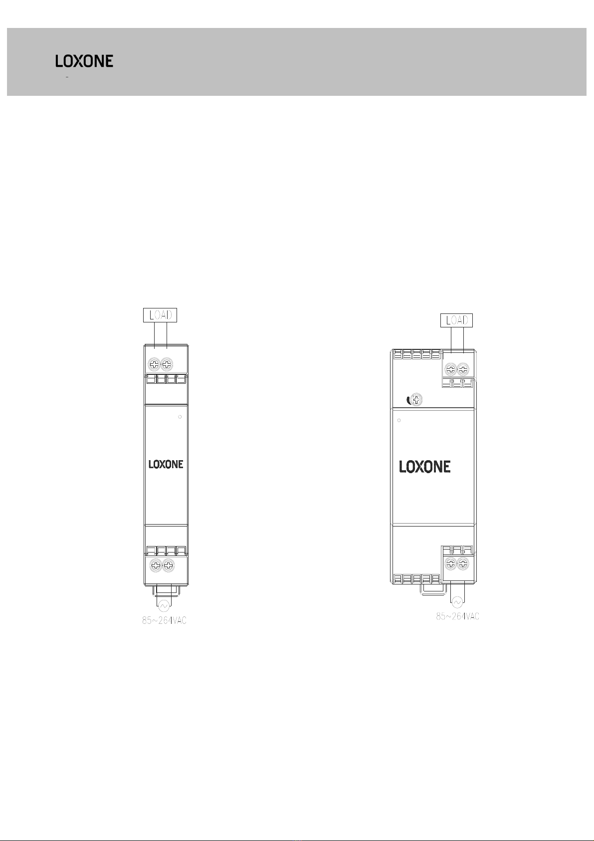
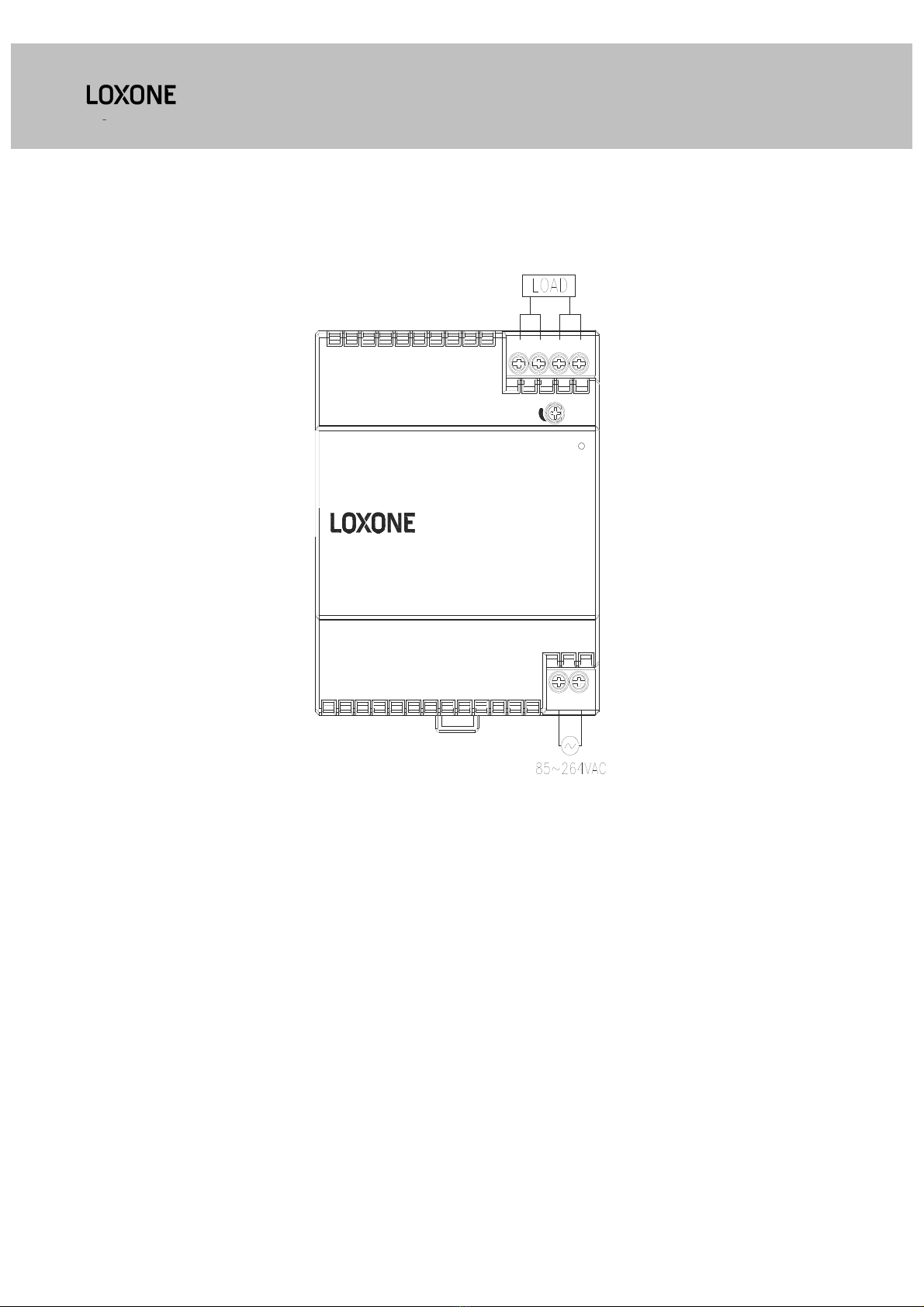
4-1. Input Voltage Range
Input voltage range is single phase 85 ~ 264VAC
(47~63Hz)(not safety approved condition).For cases
where conformance to various safety specs (UL, CSA,
EN) are required, input voltage range will be 100 ~
240VAC (50/60Hz). Power supply can withstand
300VAC surge for 5 seconds during operation. Input
voltage which is out of specification may cause unit
damage.
4-2. Output Voltage Range
Output voltage is set to the rated value at
shipment. 200143 output voltage is not adjustable.
200001 and 200002 V.ADJ trimmer on the front
panel side can be used to adjust the output
voltage within the range specified (refer to
specifications for adjustable range).
To turn the trimmer clockwise, the output voltage
will be increased. Take note when the output
voltage is increased excessively, over voltage
protection (OVP) function may
trigger and output voltage will be shut down..
Furthermore, when increasing the output voltage,
reduce the output current so as not to exceed the
maximum output power.
4-3. Inrush Current
This series has used Power Thermistor to protect the
circuit from Inrush Current. Please carefully select
input switch and fuse in cases of the high
temperature and re-input the power.
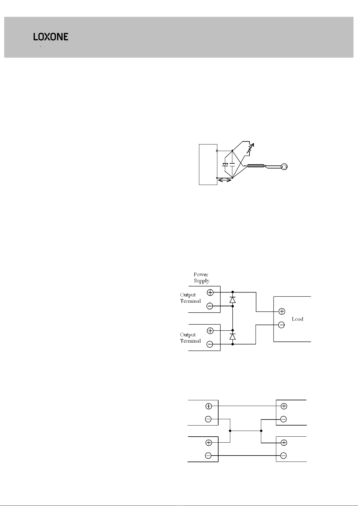
4-4. Over Voltage Protection ( OVP )
The OVP function (Inverter shutdown method, manual
reset type) is provided. OVP function operates within
specified range (refer to specification) . To reset OVP,
remove the input of power supply for a few minutes,
and then re-input. OVP value is fixed and not to be
adjusted externally. Never apply more than rated
output voltage to output terminal, which may leads to
damage. In the case of inductive load, put protective
diode in series to the output power line.
4-5. Over Current Protection ( OCP )
Hiccup mode with automatic recovery.
OCP function operates when the output current
exceeds OCP specification. The output will be
automatically recovered when the overload condition
is cancelled. Do not operate overload or dead short
conditions for more than 30 seconds, which could
result in damage or insulation failure. Due to internal
protective function , output short causes 200143,
200001 hiccup or latch up, and causes 200002
hiccup.
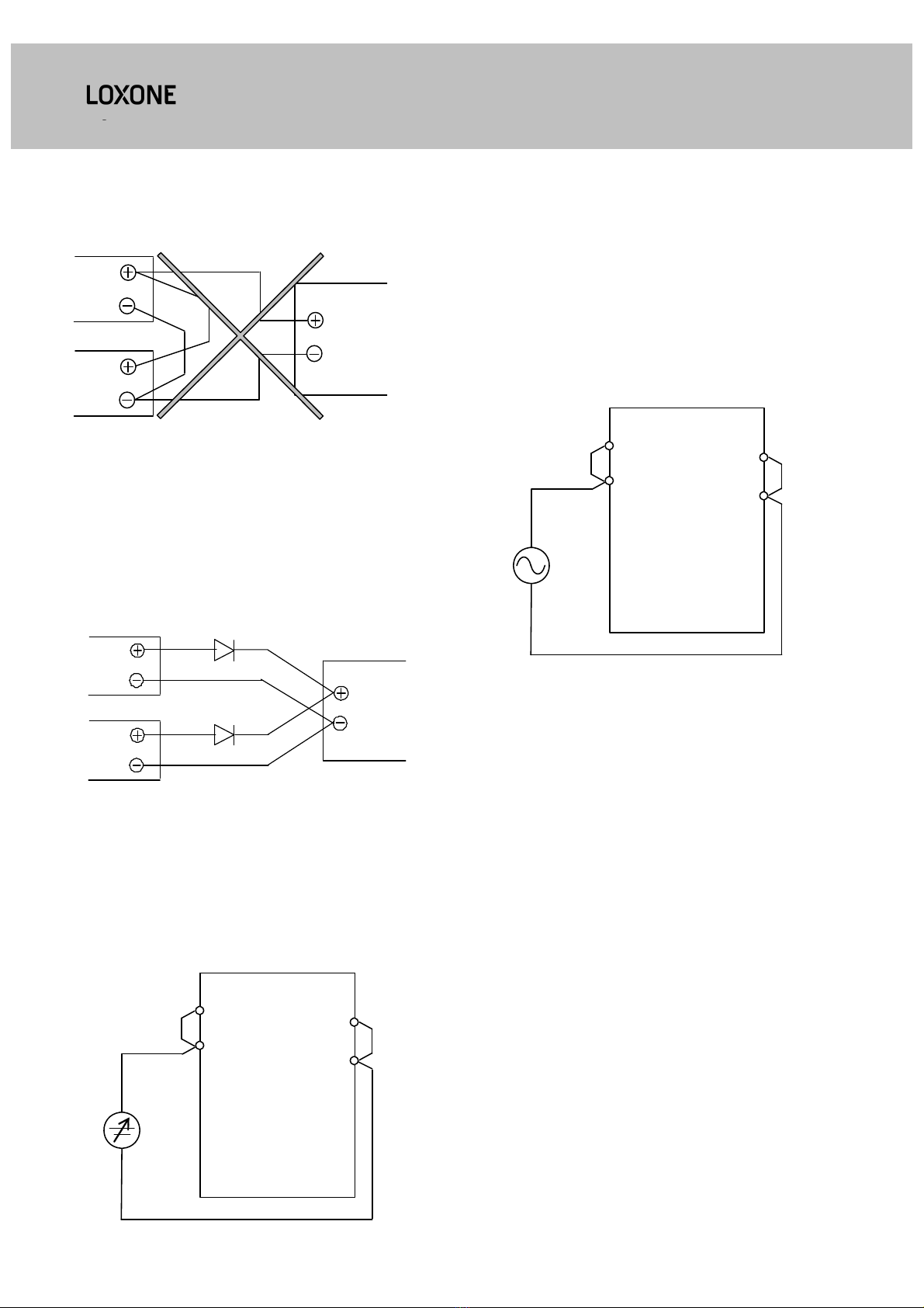
4-7. Series Operation
For series operation, either method (A) or (B) is
possible.
Method ( A )
Method ( B )
Output
Terminal
Output
Terminal
Power
Supply
Load
Load
INSTRUCTION MANUAL

4-8. Parallel Operation
(A) To increase the output current is not possible.
Load
Output
Terminal
Output
Terminal
Power
Supply
(B) To use as Back-up Power Supply
(C) Set power supply output voltage higher by the
forward voltage drop(VF) of diode
2. Adjust the output voltage of each power
supply to be the same.
3. Use within the specifications for output
voltage and output power.
Output
Terminal
Output
Terminal
Load
Power
Supply
4-9. Isolation Test
Isolation resistance between input and output shall
be more than 100M at 500VDC. For safety
operation, voltage setting of DC isolation tester must
be done before the test. Ensure that the unit is fully
discharged after the test.
Intput ~ Output : 500VDC 100M or
more
AC(L)
AC(N)
+
-
Isolation
Tester
4-10. Withstand Voltage
This series is designed to withstand 3.0kVAC between
input and output for 1 minute. When testing
withstand voltage, set current limit of the withstand
voltage test equipment to 20mA. The applied voltage
must be gradually increased from zero to the testing
value and then gradually decreased for shut down.
When timer is used, the power supply may be
damaged by high impulse voltage at timer switch on
and off. Connect input and output as follows.
Input ~ Output: 3kVAC 1min. ( 20mA )
AC(L)
AC(N)
+
-
Withstand
Voltage
Tester
4-11. Class 2 limited power source
UL1310 class 2 approved
models: 200143
200001
INSTRUCTION MANUAL

5. Mounting Directions
5-1. Mounting Directions
Recommended standard mounting method is ( A ).
Please do not use installation method ( B ). Refer to
the derating below. Do not exceed the load
deratings. Keep ventilation holes at top and bottom
clear, leave enough space for cooling. Please
contact your local sales for particular application
related to surrounding space.
Normal mounting (A)
LN
24V GND
24-28VDC/1.25-1.07A
DC OK
V.ADJ
Class 2 output
100-240VAC
Back Down Mounting (B)
5-2. Output Derating
( Ta: measured at 50mm or less beneath the unit)
200143
200001
200002 115~240VAC
100~115VAC
INSTRUCTION MANUAL

(1) Internal fuse information:
(2) External fuse rating:
Refer to the following fuse rating when selecting the
external fuses that are to be used on input line. Surge
current flows when line turns on. Use slow-blow fuse
or time-lag type fuse. Do not use fast-blow fuse. Fuse
rating is specified by in-rush current value at line turn-
on. Do not select the fuse according to input current
(RMS.) values under the actual load condition.
8-1. Power supply mounting on DIN RAIL
(TS35 or equivalent)
Make sure input and output wire disconnected
when mount power supply onto rail
(1) Tilt the unit slightly rearwards, fit the unit over
top hat rail.
(2) Slide it downward until it hits the stop.
1000411 2010T1A250V ( Walter)
(AC250V T1A)
200001 2010T1.6A250V (Walter)
(AC250V T1.6A)
200002 0215004.MXEP (Littelfuse)
(AC250V T4AH)
200143 AC250V 1A~8A
200001 AC250V 1.6A~8A
200002 AC250V 4A~8A
6.Wiring Method
The output load line and input line shall be
separated and twisted to improve noise
sensitivity.
Use all lines as thick and short as possible to
make lower impedance.
Noise can be eliminated by attaching a
capacitor to the load terminals.
EMI reduction performance by winding the
cable around the toroidal ferrice core several
times. Use any appropriate commercially
available ferrite core from local vendor.
Recommened wire type: solid and stranded,
AWG 12~24(wire strip length:4~5mm , 5mm
max).
7.Internal and External Fuse Rating
INSTRUCTION MANUAL

(3) Press against the bottom front side for locking.
Shake the unit slightly to check the locking action.
8-2. Power supply removal from DIN RAIL
Switch main power off and disconnect your
system from the supply network. Move the removal
hole on the rear down edge downwards by rotating
screw driver. Gently lift lower front edge of the unit
(tipping) and remove it.
9. Before concluding that the unit is at fault...
Before concluding that the unit is at fault, make the
following checks.
Check if the rated input voltage is connected.
Check if the wiring of input and output is correct.
Check if the wire material is not too thin.
Check if the output voltage control ( V.ADJ ) is
properly adjusted.
Check if the output current and output wattage
do not over specification.
Audible noise can be heard during Dynamic-
Load operation.
Audible noise can be heard when input voltage
waveform is not sinusoidal wave.
10. Returns
Please contact your local sales office or visit our
website to arrange return of any faulty product..
11. LOX-1 series UL508 Listed Condition
1) Wire Requirement
Use minimum 75°C
wire
Use copper conductor
only
2) For use in a Pollution degree 2 environment only
3) These products are considered for use where
maximum surrounding air temperature does not
exceed 71°C. When installing these products
please refer to section 5-2 for deratings.
4) Indoor use only
Connector Recommended Wire Max. Torque
INPUT
(L, N)
solid and stranded,
AWG12~24(wire strip
length:4~5mm ,
5mm max).
0.51N.m
(4.5Lb.inch)
OUTPUT
(24V,GND)
solid and stranded,
AWG12~24(wire strip
length:4~5mm ,
5mm max).
0.51N.m
(4.5Lb.inch)
INSTRUCTION MANUAL

Loxone Electronics GmbH
Smart Home 1 4154
Kollerschlag Austria
Tel: +43 7287 7070
INSTRUCTION MANUAL
This manual suits for next models
2
Table of contents
Popular Power Supply manuals by other brands

fanttik
fanttik EVO300 user manual

Intepro systems
Intepro systems PS 9080-50 1U user manual

SilverStone
SilverStone ST45SF Multilanguage manual

Agilent Technologies
Agilent Technologies 6033A Service manual

Fellowes
Fellowes esi FlexCharge4CX Assembly instructions

Life technologies
Life technologies novex PowerEase 500 user guide