LS ELECTRIC HFS Series User manual

The right choice for the ultimate yield!
LS ELECTRIC strives to maximize your profits in gratitude for choosing us as your partner.
Low Harmonic Filter
고조파 필터
-한국어
-English
주의사항 (Safety Instructions)
사용 전에 『안전을 위한 주의사항』을 반드시 읽고 정확하게 사용하여 주십시오.
시스템 설계 및제품 사용시 반드시 완전본 매뉴얼을 읽고 정확하게 사용하여 주십시오.
Read this guide and full version installation manual carefully before installation, wiring, operating,
servicing or inspecting this equipment.
HFS Series 간편본 설치안내서 (Quick Installation Guide)

본사용설명서는 전기전자 기기 관련 기본 지식이 있는 사용자를 위해 제작되었습니다.
HFS 는LS Electric 고조파 필터의 시리즈명 입니다.
사용설명서 개정 이력
No
Date
Edition
Change
1
2020.4
First Release

본간편본 설치안내서(Quick Installation Guide)는설치 시간단한 참고사항만 요약된 안내서입니다.
HFS 고조파 필터의 안전한 설치 및운용과 최대의 성능을 위하여 www.ls-electric.com 의다운로드 섹션에
게시된 최근 버전의 Full version 사용설명서를 참조하여 주십시오.
제품을 사용하기 전에 안전을 위한 주의 사항을 반드시 읽고 제품을 올바르게 사용하십시오. 제품을
설치하거나 사용하기 전본안전을 위한 주의사항, 제품설명서, 제품사양 및사용설명서의 경고내용을
반드시 숙지하십시오.
1. 제품 설치 전참고사항
1) 설치 전배송용기와 제품을 주의 깊게 검사하십시오. 육안상 손상이 발견될 경우 필터를 설치하지
말고 공급 대리점이나 본사에 연락하여 주십시오.
2) 고조파 필터의 용량에 따른 중량을 확인하시고, 귀사에서 정의한 중량물 취급지침을 따르십시오.
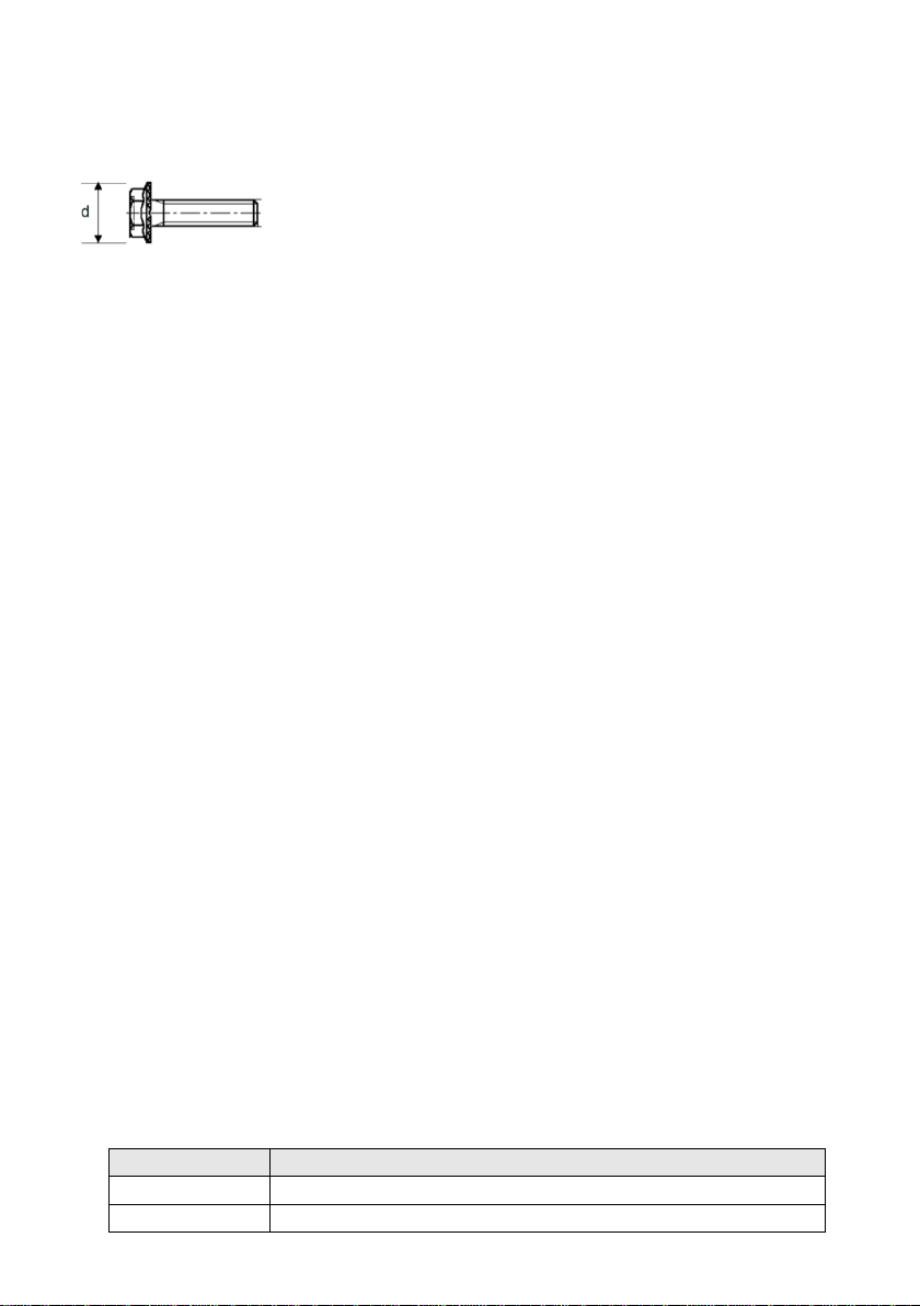
3) 필터 플랜지가 제공하는 고정 홀에 적합한 크기의 나사산 볼트를 사용하십시오. 볼트의 강도 등급은
설치하는 필터의 무게와 설치하는 표면의 재질에 따라 사용자가 결정하여야 합니다.
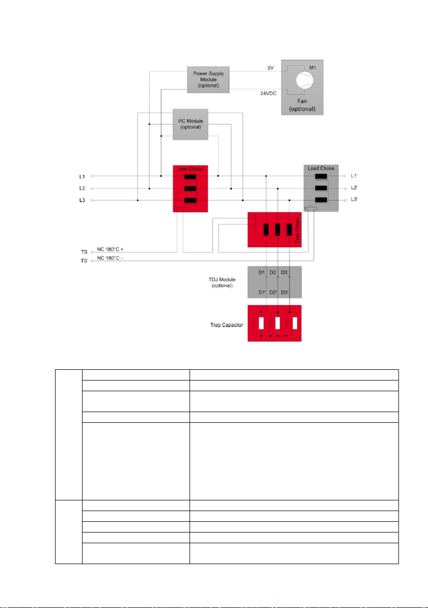
4) 보호 접지(PE) 단자에 필터를 연결하십시오.
5) 전원을 차단한 후입력 3상전원 케이블을 배선하십시오.
6) 필터 케이블 단자 체결 시필터의 라벨 또는 사용설명서에 명기된 권장 체결토크를 준수하십시오.
7) 케이블 굵기는 용량에 따라 국가별 표준규격을 참조하여 주십시오.
8) 과열 모니터링을 위한 추가 단자를 제공합니다. 필터 사용시 과열 모니터링 단자를 배선하여
운전자에 경고 및운전 정지가 가능한 시퀀스에 연동하여 주십시오.
2. 안전 주의사항 및규정
1) 장비 설치, 시동, 작동 및유지보수(있는 경우)는전기 시스템의 안전 절차에 익숙한 숙련되고 인증된
전기 기술자나 정비사가 수행해야 합니다. 자격이 없는 사람은 전력 품질 필터를 사용, 설치, 작동
또는 유지 관리할 수없습니다.
2) 전력 품질 장비 운용에는 고전압이 연결됩니다. 필터의 통전된 부분을 취급하기 전에 항상 전원을
차단하고 캐패시터가 안전 수준(<42V)으로 방전될 때까지 충분한 시간이 경과되도록 하십시오. 잔류
전압은 라인 대라인 및접지 대라인 두가지를 모두 측정해야 합니다.
3) 장비의 올바른 보호 접지를 확립하고 해당 국가 및지역 규정에 따라 공급 전압으로부터 사용자를
보호해야 합니다. 전기 장비를 취급, 설치, 작동 또는 유지 관리할 때는 항상 귀사에서 정의한 안전
절차와 해당 국가 전기 법규에 따라 실천하십시오.
4) 항상 필터를 보호 접지(PE)에먼저 연결한 다음 전원케이블을 배선하십시오. 필터를 철거할 때에는
마지막에 접지 케이블을 분리하십시오.
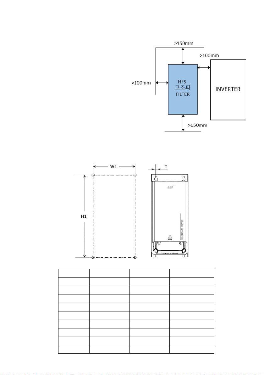
5) 일반 설치 및환경 조건 참고 사항을 주의 깊게 따르십시오. 냉각팬이 내장된 제품의 경우 효율적인
공기 순환을 방해할 수있는 장애물이 없는지 확인하십시오. 고조파 필터 사용 시카탈로그 및
사용설명서에 명기된 전기적, 기계적, 온도 및주변 환경사양에 준수하여 사용하여 주십시오.
6) 고조파 필터의 내부 모듈은 발열손실이 발생하는 전기 부품입니다. 제품 내부 부품 및외부 표면은
부하 작동 조건에서 발열이 발생할 수있습니다. 동작중 커버를 절대 제거하지 마십시오. 내부
발열부분의 인체 접촉 시화상의 우려가 있으므로 절대 접촉하지 마십시오. 운전 정지 후인체
발열부품에 대한 인체 접촉 시에도 반드시 발열에 대한 주의가 필요합니다. 운전 정지 후커버 분리
및점검 시반드시 보호 장갑을 착용하여 주십시오.
7) 2000m 이상의 고도에서 설치하기 전에 LS Electric 에문의하십시오.

8) LS Electric의인버터를 제외한 기타 장치에 고조파 필터를 적용하는 경우 제품 성능 및안정적
운영에 대해 보증하지 않습니다. LS Electric 인버터를 제외한 다른 장치 및Application 에적용할
경우에는 본사에 문의하여 주시기 바랍니다. LS Electric과제조사는 자사 적용사양을 벗어난 필터
사용으로 인한 공정 다운타임이나 손실, 손상에 대해 책임을 지지 않습니다.
9) 확인이 필요하거나 추가적인 문의가 있는 경우 LS Electric 본사로 문의하여 주십시오.
3. 시스템 요구사항
고조파 필터의 성능 수준은 다음과 같은 시스템 조건이 충족될 때보장됩니다
1) 부하의 유형 : 6-pulse front-end 다이오드 정류기가 있는 3상장비
2) 전류원의 종류 : 중성점이 없는 3 상전력라인
3) 전원 임피던스 : < 3% (정격 필터 용량 기준)
4) 전원 주파수 : 50Hz ±1Hz (HFS-XXXX-3-50), 60Hz ±1Hz (HFS-XXXX-5-60)
5) 전원 전압 : 정격 전압 ±10%
6) 전원 전압 Unbalance : < 1%
7) 전원 전압 왜곡율 : THVD < 2%

4. 제품 구성
단자
전원 입력 측L1 / L2 / L3
3상터미널 블록
인버터 측L1’ / L2’ / L3’
3상터미널 블록
과열 Alarm 출력 TS / TS’
Thermal Switch 180℃에연결되어 과부하 감지 (Normal Closed) 무전
원접점 출력
PE
접지단자
TDJ module
Trap Capacitor 단자
D1 / D2 / D3
D1’ / D2’ / D3’
3상터미널 2세트
Trap Disconnection Jumper 단자
양단에 개폐기(MC)를설치하여 인버터 기동 시투입합니다.
인버터에 전원이 투입되지만 정지하여 있는 경우 혹은 20% 미만의
부하로 운전하는 경우 고조파필터 입력 단캐패시터 전류를 저감하고,
진상역률을 방지합니다. 개폐기(MC)를설치하지 않고 장시간 정지상
태에서 전원 투입 시캐패시터의 수명이 감소할 수있습니다.
모듈
초크(리액터)
온도 센서를 포함한 Power Magnetic 구성요소
캐패시터(Capacitor)
방전 Resistor를포함한 Power Capacitor
팬
내부 공기냉각용 Fan, 현장 교체 가능
Power Supply Module
Fan 전원 공급용 DC 24V Power Supply
RC Module
높은차수의 고조파 전류 감쇄 및EMC Filter와의
Resonance(공명) 회피기능

제품 내부 구조는 아래와 같습니다. 아래 그림은 참조용 그림이며 제품 배선 시에는 전체 COVER를분리할
필요가 없으며 하단 단자대 커버만 분리하면 배선이 가능합니다.
필터의 내부 구조는 모든 프레임이 공통적이며, 제품 내부는 상단과 하단으로 분리되어 있습니다.
단, Load Reactor의경우 A~F Frame은상단에 위치하며, G~H 프레임의 경우 하단에 위치합니다.
A~C 프레임의 경우 강제 Cooling Fan 이필요로 하지 않으며, 제품에 Fan 이적용되어 있지 않습니다.
대용량 제품군중 60HZ HFS-0320-5-60 이상 모델과 50HZ HFS-0260-3-50 이상의 용량에는 RC Damper
모듈이 필요로 하지 않으며 제품에 적용되어 있지 않습니다.
< 제품 내부 상단 >
< 제품 내부 하단 >

5. 설치
우측 그림과 같이 HFS 고조파 필터 설치 시
충분한 공기 흐름을 보장하기 위하여 주변의
이격 거리를 확보하여 주시기 바랍니다.
제품의 점검 및유지 보수 시전면 커버
탈착을 위한 접근 공간을 고려하여
설치합니다. 판넬 Door를닫고 정상 가동하여
충분한 시간이 경과한 후에도 판넬 내부 필터
주변 온도가 45℃미만으로 유지될 수있도록
판넬의 공기 순환 및냉방 대책을
강구하십시오. 판넬 내부의 온도가 높은
환경에서 필터를 동작 시에는 정격전류가
Derating 되므로 낮은 부하율에서도 필터
내부에 내장된 온도센서에서 과열 알람이
출력될 수있습니다.
1) 제품 Frame별속판 부착 시타공 홀위치
Frame
W1 [mm]
H1 [mm]
T [mm]
A
120
340
7
B
120
405
7
C
150
460
7
D
180
540
11
E
220
680
11
F
250
730
11
G
280
920
11
H
390
1115
11
J
480
1350
11

2) 나사 규격
HFS 고조파 필터는 아연 코팅된 육각 강철 볼트를 권장합니다. 필터의 무게를 고려해 적절한 나사를
선택하여 주십시오. 헤드의 직경은 아래 치수를 초과해서는 안됩니다.
M6: d ≤14.2mm, M10: d ≤21.2mm
3) 배선 방법
입력 전원이 차단되어 있는지 반드시 확인하십시오.
상세사항은 완전본 매뉴얼을 참조하여 주십시오.
가.접지 배선
설치 현장 및국가별 안전 규칙을 참조하십시오.
보호 접지 케이블을 HFS 고조파 필터에 가까운 적절한 접지 전위에 연결하십시오.
국가별 케이블 규격과 안전 규칙에 따라 적절한 규격의 접지 케이블을 사용하여 배선하여 주시기
바랍니다.
단자 규격에 따른 권장 체결 토크는 아래와 같습니다.
-M5 Torque : 2.2 Nm
-M6 Torque : 4 Nm
-M8 Torque : 9 Nm
-M10 Torque : 19 Nm
-M12 Torque : 25 Nm
나.필터 출력 및입력 파워케이블 배선
TDJ 단자의 JUMPER 케이블로 인해 간섭이 있을 경우 JUMPER 케이블을 분리한 후배선합니다.
상세사항은 완전본 매뉴얼을 참조하십시오.
다.TDJ 단자 배선 (캐패시터 연결 및차단을 위한 MC 개폐회로 구성)
TDJ모듈 (Trap Disconnection Jumper: 캐패시터연결분리)의Jumper 단자는 인버터가 정지하였거나
매우 낮은 부하로 운전하는 경우 필터 전단에 흐르는 Capacitive 전류를 감쇄하고, Capacitor의
수명이 감소되는 것을 방지하기 위해 Jumper 단자대에 MC(개폐기)를설치합니다.
캐패시터의 수명 감소를 방지하기 위하여 Disconnection Jumper 단자에 MC(개폐기)를설치하여
주십시오.
공장 출하시에 TDJ (Trap Disconnection Jumper) D1-D1’ , D2-D2’ , D3-D3’ 단자대에 Jumper 케이블이
배선되어 있습니다. TDJ 단자를 이용하여 인버터 정지 또는 매우 낮은 부하에서 연결된 개폐기를
Open 하여 주시기를 권장합니다. 권장 개폐기의 용량은 정격용량의 20%이상으로 산정하여 주시기
바랍니다.
개폐기 기동조건
권장사항
차단 (Open)
인버터가 정지하거나 부하율이 10~15% 미만으로 내려가는 경우
투입 (Close)
인버터가 기동하거나 부하율이 20~25% 이상 상승하는 경우

부하율에 따라 MC 투입/차단을 하는 경우는 LS 인버터의 주파수 검출 기능을 MC 기동신호로
활용할 수있습니다. 자세한 내용은 LS 인버터 사용설명서를 참조하여 주시기 바랍니다.
라.J 프레임 (HFS-0530-3-50) 필터의 AS, AS' 단자 배선
AS, AS' 단자는 무전원 상태접점이며, J프레임에만 내장되어 있는 차단기의 상태 접점입니다.
정상상태시 Closed 상태이며, 캐패시터에 단락전류가 흐르거나, 캐패시터 Disconnection 회로에
과전류, 또는 부하정지 및저부하 지속상태에서 사용자가 임의로 차단기를 차단 하였을 경우 Open
상태가 됩니다. 차단기를 투입하고 운전중 차단기 트립으로 인해 AS, AS' 단자가 open 되었을 경우
즉시 부하를 정지하고 문제점을 분석하여 주시기 바랍니다.
마.과열 알람접점 배선
TS, TS’ 과열스위치 모니터 단자는 알람 상태에서 OPEN 되는 Normal Closed 무전원 접점입니다. 써
멀스위치 180°C(UL-approved )로초크의 과부하를 감지합니다. 이를 사용 하여 원격에서 드라이브
의부하를 분리하거나 시스템 콘트롤 유닛의 알람센서로 사용할 수있습니다.
필터의 알람 모니터 스위치가 작동하였을 경우 즉시 운전 정지, 전원 차단 및문제점을 분석하여
주시기 바랍니다.
4) 참고 배선 도면
권장 Fuse 규격은 완전본(Full version) 사용설명서를 참조하여 주시기 바랍니다.

6. 제품 치수
Frame
모델명
W
(mm)
H
(mm)
D
(mm)
W1
(mm)
H1
(mm)
H2
(mm)
T
(mm)
A
HFS-0002-5-60
HFS-0004-5-60
HFS-0003-3-50
HFS-0005-3-50
160
360
185
120
340
302
7
B
HFS-0007-5-60
HFS-0011-5-60
HFS-0010-3-50
180
425
206
120
405
370
7
C
HFS-0014-5-60
HFS-0021-5-60
HFS-0013-3-50
HFS-0016-3-50
210
483
221
150
460
430
7
D
HFS-0027-5-60
HFS-0034-5-60
HFS-0044-5-60
HFS-0024-3-50
HFS-0032-3-50
HFS-0038-3-50
260
560
252
180
540
491
11
E
HFS-0052-5-60.
HFS-0066-5-60
HFS-0083-5-60
HFS-0045-3-50
HFS-0060-3-50
HFS-0075-3-50
HFS-0090-3-50
HFS-0110-3-50
290
705
318
220
680
635
11
F
HFS-00103-5-60
HFS-00128-5-60
340
752
343
250
730
684
11
G
HFS-00165-5-60
HFS-00208-5-60
HFS-0150-3-50
HFS-0180-3-50
353
960
396
280
920
863
11
H
HFS-00240-5-60
HFS-00320-5-60
HFS-00403-5-60
HFS-0210-3-50
HFS-0260-3-50
HFS-0320-3-50
HFS-0400-3-50
462
1150
456
390
1115
1053
11
J
HFS-0530-3-50
550
1455
555
480
1350
1300
11

This operation manual is intended for users with basic knowledge of electricity and electric
devices.
HFS is the official name for LS ELECTRIC Harmonic Filters.
Version History
No
Date
Edition
Change
1
December 2020
First Release

This Document is only simple quick installation guide.
Read full version installation manual carefully before installation, wiring, operating, servicing or inspecting this
equipment. In order to get the maximum benefit out of your power quality filter, please also consult additional full
version user manuals, whitepaper and other material published in the download section of www.ls-electric.com
General Safety Notes and Installation Guidelines
(Cautions and Warnings)
Power Quality Filters
1. Important Information
Do not attempt to install, operate, maintain or inspect power quality filters until you have read through the safety
notes and installation guidelines as well as installation manual and product specification. Do not use any LS
Electric product until you have a full knowledge of the equipment, safety notes and installation guidelines.
General Installation Notes
▪Please read and follow the safety and application notes below.
▪Carefully inspect the shipping container and the product prior to the installation. In case of visual
damage, do not install the filter and file a claim with the freight carrier involved.
▪Filters may be heavy. Follow the instructions for lifting heavy equipment defined by your company.
▪Use an appropriately sized threaded bolt for every mounting hole/spot provided by the filter flange.
The strength class of the bolt must be determined by the installer, depending upon filter weight and
the material of the mounting surface.
▪Connect the filter to the protective earth(PE) terminal(s).
▪Remove all line side power, then connect the phase terminal(s). The filter label may also indicate
LINE (grid side terminals) and LOAD (power electric terminals)
▪For the electrical connection of the filter terminals, apply the torque recommended on the filter label
and/or in the published filter datasheets
▪Cable or busbar cross sections have to be chosen in accordance with national and international
electric codes and applicable product standards governing the equipment that will incorporate the
power quality filters and the equipment in use.
▪Filters provide additional terminal, e.g. for over-temperature monitoring. These features have to be
properly used before energizing the filter. If uncertain, please consult your local LS Electric
representative.
▪In order to get the maximum benefit out of your power quality filter, please also consult additional
user manuals, installation manual, whitepaper and other material, published in the download section
of www.ls-electric.com These additional guidelines provide helpful hints for equipment related topics
as well as technical knowledge.
2. Safety Notes and Regulations
▪Equipment installation, start-up, operation and maintenance (if any) have to be carried out by a
trained and certified electrician or technician who is familiar with safety procedures in electrical
systems. Non-qualified persons are not allowed to use, install, operate or maintain PQ filters.
▪High voltage potentials are involved in the operation of power quality equipment. Always remove
power supply before handling energized parts of the filter, and let ample time elapse for the capacitors
to discharge to safe levels (<42V). Residual voltages are to be measured both line to line and line to
earth.
▪Correct protective earth of the equipment must be established and the user must be protected against
supply voltage in accordance with applicable national and local regulations. Always practice the
safety procedures defined by your company and by applicable local electric codes when handling,

installing, operating or maintaining electrical equipment.
▪Always connect the filter to protective earth (PE) first, then continue with the wiring of phase/neutral
terminals. When decommissioning the filter, remove the PE connection at the end.
▪Follow the general installation and environmental condition notes closely. Ensure that cooling slots
(if any) are free from obstructions that could inhibit efficient air circulation. Operate the filter within its
electrical, mechanical, thermal and ambient specifications at all times.
▪The internal module of the low harmonic filter is an electrical component that generates heat loss.
Internal components and external surfaces of the product may generate heat under load operating
conditions. Never remove the cover during operation. Never touch the internal heating part as it may
cause burns. It is necessary to beware of human body contact with heating parts even after stopping
the operation. Be sure to wear protective gloves when removing and inspecting the cover after
stopping operation.
▪At altitudes above 2000m, please contact LS Electric prior to installation.
▪Product performance and stable operation are not guaranteed when low harmonic filters are applied
to devices other than LS Electric’s inverters. In case of application to devices and applications other
than LS Electric inverter, please contact local LS Electric representative. LS Electric and the
manufacturer will not assume liability for any process downtime, loss or damage resulting from the
usage of filters outside their application specifications.
▪In case of uncertainty and questions please contact to your local LS Electric partner for assistance
3. Performance guarantee
Selecting and installing the appropriate HFS passive harmonic filter in a variable frequency AC drive application,
variable speed drive application within our published technical specifications we guarantee that the input current
distortion will be less than or equal to 5% THID for standard HFS series filters at rated power. HFS harmonic
filters can also provide similar performance in other drive applications such as constant torque, DC drives or
other phase controlled rectifiers, e.g. SCR drives, but actual THID levels can vary by load and/or speed and/or
firing angle of thyristors and therefore cannot be guaranteed. Consult your local LS Electric representative for
assistance when applying HFS harmonic filters on these types of equipment.
3.1. Minimum system requirements
Performance level of this filter is guaranteed when the following system conditions are met:
▪Type of load : Any 3-phase equipment with front-end six-pulse diode rectifier
▪Type of source : 3-phase power line without neutral
▪Line impedance : < 3% (calculated for the rated filter power)
▪Line frequency : 50Hz ±1Hz (HFS-XXXX-3-50), 60Hz ±1Hz (HFS-XXXX-5-60)
▪Line voltage : Nominal line voltage ±10%
▪Line voltage unbalance : < 1%
▪Line voltage distortion : THVD < 2%
3.2. Important user notice
HFS Low Harmonic Filters are designed for the operation on the input (grid) side of LS Electric
inverters in a three-phase power system. In addition, filter suitability for a given application should
be determined by the user. LS Electric will not assume liability for any process downtime, loss or
damage resulting from the usage or application of HFS Low Harmonic Filters that are outside of
their specification. HFS Low Harmonic Filter should not be used for single phase or split-phase
applications.

4. Functional Diagram
Figure 1. Functional diagram
Filter
terminals
Line L1/L2/L3
Line side 3phase terminal
Load L1’/L2’/L3’
Load side 3phase terminal
Overheating alarm TS / TS’
Connected to Thermal Switch 180℃ to detect overload
(Normal Closed) and output non-power contact
PE
Ground terminal (Protective Earth)
TDJ module
Trap Capacitor terminals
D1 / D2 / D3
D1’ / D2’ / D3’
2 sets of 3-phase terminals
Trap Disconnection Jumper terminal
Switches (MCs) are installed at both ends and are turned on
when the inverter starts.
When power is supplied to the inverter but it is stopped, or
when operating with a load of less than 20%, the harmonic
filter input terminal capacitor current is reduced and the
leading power factor is prevented. The lifespan of the
capacitor may be reduced when power is supplied in a long
term stopped condition without installing a switch (MC).
Function
blocks
Chokes
Power magnetic components incl. temperature sensors
Capacitors
Power capacitors incl. discharge resistors
Fan
Field replaceable fan for choke air cooling
Power Supply Module
Internally generate 24 V DC source for fan supply
RC Module
Attenuation of high-order harmonic current and avoidance
function of resonance with EMC filter
The very compact and neat design of HFS harmonic filters is realized by a two-stage construction. The filter
construction of all frame size are identical, except the position of the load choke. The load choke is build on the
upper-stage of the filter for frame size A- F, and on the lower-stage of the filter for frame sizes G – H, which are
explained in detail in the following sections.

The general design of the HFS harmonic filter with fan module, aux. power supply module, the design and
construction of upper-stage is shown in Figure 2. There are load choke Lo, trap capacitor Ct, trap disconnect
jumper, power terminal and fan module visible on the upper-stage. The design and construction of the lower-stage
is shown in Figure 3. The line choke Li, trap choke Lt, RC damper module are constructed on the base plate,
which contains screw holes for wall mounting.
Figure 2. Upper-stage of HFS harmonic filter
Figure 3. Lower-stage of harmonic filter
5. Filter Installation
Please follow the simple steps below to ensure a safe and reliable filter function for many years. Please do also
always follow the general safety and installation guidelines provided within this document as well as relevant
local, national or international standards that are applicable.
Step 1: Visual inspection
All LS HFS harmonic filters have undergone rigorous testing before they left our ISO
9001:2008 certified factories. They are packaged with great care in a sturdy container for international shipment.
However, carefully inspect the shipping container for damage that may have occurred in transit. Then unpack the
filter and carefully inspect for any signs of damage. Keep the shipping container for future transportation of the
filter. In the case of damage, please file a claim with the freight forwarder involved immediately and contact your
local LS Electric partner for support. Under no circumstances install and energize a filter with visible
transportation damage. If the filter is not going to be put in service upon receipt, store within the original
container in a clean, dry location, free of dust and chemicals and with respect to named temperature limits

Step 2: Mounting
HFS harmonic filters are best installed as close as possible to the non-linear load. Ideally they are mounted next
to the rectifier or motor drive inside the electrical cabinet or control room. All HFS harmonic filters wall-mounting
installation.
Important:
In order to ensure sufficient air flow, keep a clearance of
min.150mm above and below the filter to walls or other
components. Additional work to access the device,
caused by not respected clearance distances, will be
accounted separately.
It must be ensured that the environmental temperature
is kept below 45°C with appropriate thermal
management (e.g. cabinet cooling). Filter operation in
environments with higher temperatures require a
temperature derating.
Screw hole positions for wall mounted filters
All dimensions in : [mm], 1inch = 25.4mm
Frame
W1 [mm]
H1 [mm]
T [mm]
A
120
340
7
B
120
405
7
C
150
460
7
D
180
540
11
E
220
680
11
F
250
730
11
G
280
920
11
H
390
1115
11
J
480
1350
11
Screw selection: LS Electric recommends zinc coated hex ribbed flange steel bolts. Respect filters weight for
appropriate choice of screws! Head diameters must not exceed these dimensions:
M6: d ≤14.2mm, M10: d ≤21.2mm

Filter placement:
1. Set screws loose into wall, leave 5mm distance from head to wall.
2. Lift filter with appropriate crane, smallest types (up to 25kg) may be lifted
manually by two persons.
3. Place filter first onto lower screws…
4. ...then position it through backplane head openings on upper screws.
5. Fix screws with appropriate torque (depending upon the material of the
back plane and local standards).
Step 3: Wiring
1) Verify safe disconnection of all line side power.
Consult your local safety instructions.
2) Carefully connect protective earth (PE) wire to adequate earth potential close to HFS
harmonic filter.
Use a wire diameter of equal or bigger size as foreseen for line/load side power cables –according
to your local codes and safety instructions.
3) Connect PE wire of HFS harmonic filter with appropriate cable lug to threaded stud.
| torque M5: 2.2 Nm
| torque M6: 4 Nm
| torque M8: 9 Nm
| torque M10: 19 Nm
| torque M12: 25 Nm
4) Connect harmonic filter load side terminals L1’, L2’, L3’ to respective motor drive inputs.
See below table for the recommended wire size and torque. Use stranded copper wire with a temperature rating
of 75°C or higher.
Frame
Bolt thread
Cable standard
Tightening torque
[Nm]
Cable Lug
Maximum diameter
[mm]**
AWG
mm2
A
M3
14-22
0.4-2.5
0.5
7
B,C
M4
10-22
0.4-6
1.2
10
D
M6
6-18
0.75-16
3
15
E,F
M8
1/0-8
10-50
8
15
G
M8
3/0-8
10-95
8
17
H
M10
3/0-500kcmil
95-240
10
35
J
M16
350-750kcmil
185-400
10
48
Note. ** It is recommended to use cable lugs when wiring.
An optional workflow to connect power terminals without having the TDJ module in way is applied. You
might consider following these steps:
Connecting power terminals of passive harmonic filters ordered with TDJ module can be facilitated by removing
the trap disconnect wires while connecting the cables to the main terminals. Afterwards the trap disconnect
jumper cables need to be applied to the original position again. Please follow these steps: Open terminals D1-
D1’, D2- D2’and D3- D3’, remove the wires, add main terminals and then fix wires on terminals D1- D1’, D2-
D2’and D3- D3’ again. The recommended torques given on the terminal label must be applied.
Remarks regarding IP 20 enclosure
▪To connect HFS harmonic filter line and load side terminals, the finger guard has to be removed as a
first step, and be installed again when the line and load side terminals are connected. The screw thread
and torque value for all the frame sizes are:
| Screw thread: M5
| Screw torque value: 4Nm
▪The metal finger guard for frame sizes E, F and G are equipped with
grommets, whilst finger guard H is equipped with stepped collars. Modify the
stepped collars according to the cable isolated diameter, 5-10mm margin is
recommended to feed the cable easier.

▪Note that if the cable lug is wider than the cross-section width/diameter of the finger guard (see below
table),do not add cable lugs before feeding all cables though the finger guard. Crimp cable lug when the
cables are fed through the finger guard.
Frame
Finger guard cross-section width/diameter (mm)
Material
A
5.5
Plastic
B
8.0
Plastic
C
8.0
Plastic
D
11
Plastic
E
14
Metal
F
14
Metal
G
18.5
Metal
H
30
Metal
J
42
Metal
▪Install shrinking tube for the uninsulated cable lug to fulfill the clearance and creepage requirement.
▪To install finger guard for frame size J, firstly connect the load and line
side terminals, then install the upper part of the finger guard by placing
the cables through the slots and tightening the screw on the top, thirdly
close the other part of the finger guard. The bottom part of the finger
guard shall be pushed as close as possible to the cable, and tighten the
other two screws on the sides.
Note: In case the cables on the power terminals are installed without cable lug, it
is recommended to follow the maintenance manual closely.
5) Use wired trap circuit or install external capacitive current control.
For configurations with TDJ option (refer to Tables 4, 5, 6), terminals D1- D1’, D2- D2’and D3- D3’ are
delivered with installed jumpers. When interconnected via an external capacitor contactor (not supplied by
LS Electric) they allow for load dependent disconnection of the trap circuit, if needed. Thus capacitive
current can be minimized for low load operation.
Estimation of required contactor size: The nominal power rating in kW multiplies 20% and the grid voltage,
then divided by the nominal voltage
THE USE OF CAPACITIVE SWITCHES/CONTACTORs IS REQUIRED. OTHERWISE CAPACITOR
LIFETIME MAY BE REDUCED.
6) Connect monitor switch TS- TS’
The monitor switch is a relay contact, which is open in ALARM state. It is constituted by a thermal switch
NC 180°C (UL-approved) to detect overload of chokes. It may either be used to remotely disconnect the
drive’s load via respective input of drive control (check drive manual) or as alarm sensor for system
control unit.
AN ENGAGED MONITOR SWITCH MUST LEAD TO IMMEDIATE LOAD SHUTDOWN AND
INVESTIGATION OF THE PROBLEM.
7) Connect auxiliary switch AS- AS’
(only relevant for frame J filter types HFS-0530-3-50)
AN ENGAGED AUXILIARY SWITCH MUST LEAD TO IMMEDIATE LOAD SHUTDOWN AND
INVESTIGATION OF THE PROBLEM
The auxiliary switch is a contact, which indicates state of circuit breaker. It is closed under normal
operation (CB on) and is open in abnormal condition (CB off). Abnormal condition can be a short circuit in
the trap capacitors, overcurrent in the trap circuit, too hot ambient temperature or switch-off status in low
load condition (use of motor mechanism together with the circuit breaker –check relevant section in full
version user manual).

8) Connect harmonic filter line side terminals L1, L2, L3 to power input protection
(current limiting fuses –see below).
Cable wiring please refer to the remarks for the 4) load side cable wiring.
Note: Finger guard must be installed in order to achieve IP 20 protection.
When the finger guard is not installed, LS Electric do not guarantee IP 20 protection.
9) Fuse
HFS Harmonic filters need external over-current protection for compliance with UL/cUL standard.
Fuses and associated fuse holders must be UL listed and rated for 100kA SCCR supplies.
Please refer to requested fuse current ratings for UL class J and in full version user manual, where UL
compliance is not mandatory, for IEC class gG. The fuse rating is independent of the supply voltage.

6. Dimension
Frame
Description
W
(mm)
H
(mm)
D
(mm)
W1
(mm)
H1
(mm)
H2
(mm)
T
(mm)
A
HFS-0002-5-60
HFS-0004-5-60
HFS-0003-3-50
HFS-0005-3-50
160
360
185
120
340
302
7
B
HFS-0007-5-60
HFS-0011-5-60
HFS-0010-3-50
180
425
206
120
405
370
7
C
HFS-0014-5-60
HFS-0021-5-60
HFS-0013-3-50
HFS-0016-3-50
210
483
221
150
460
430
7
D
HFS-0027-5-60
HFS-0034-5-60
HFS-0044-5-60
HFS-0024-3-50
HFS-0032-3-50
HFS-0038-3-50
260
560
252
180
540
491
11
E
HFS-0052-5-60.
HFS-0066-5-60
HFS-0083-5-60
HFS-0045-3-50
HFS-0060-3-50
HFS-0075-3-50
HFS-0090-3-50
HFS-0110-3-50
290
705
318
220
680
635
11
F
HFS-00103-5-60
HFS-00128-5-60
340
752
343
250
730
684
11
G
HFS-00165-5-60
HFS-00208-5-60
HFS-0150-3-50
HFS-0180-3-50
353
960
396
280
920
863
11
H
HFS-00240-5-60
HFS-00320-5-60
HFS-00403-5-60
HFS-0210-3-50
HFS-0260-3-50
HFS-0320-3-50
HFS-0400-3-50
462
1150
456
390
1115
1053
11
J
HFS-0530-3-50
550
1400
555
480
1350
1300
11
Table of contents