Healthe Air User manual
life in a different light
Healthe Air
User Guide
formerly Cleanse Troffer
Air Sanitizing
Retrot Troffer

Healthe Inc. |3905 W Eau Gallie blvd, Suite 101, Melbourne, FL 32941 |877.999.5742 |healtheinc.com
2
Healthe Inc. |3905 W Eau Gallie blvd, Suite 101, Melbourne, FL 32941 |877.999.5742 |healtheinc.com
3
PACKING LIST:
• Installation guide
• Warning label to be attached to luminaire
• Universal Mounting Adapter brackets (including #8 sheet metal screws X
6 pcs)
• Healthe Air Retrot xture
• Electronic connection kit (Junction Box Cover X 1 pc, Wire Nuts X 3 pcs,
#8 sheet metal screws X 2 pcs)
TOOLS NEEDED:
• #2 Phillips Screwdriver
• Electric Drill with #2 Phillips bit
• Pliers
Installation Guide
INSTALLATION INSTRUCTION
OFF
1. Before opening and disassembling the xture, make sure the power
has been turned off through the main circuit breaker. (See Fig. 1.)
3. Open and remove existing troffer wiring compartment cover.
This product can only be installed into a troffer xture in which
the diffuser, reector and uorescent lamps are removable
2. Remove diffuser (if applicable), reector, uorescent tube, and lamp
holder from the existing troffer housing. Empty housing from the
existing xture is shown in Fig. 2.
Fig. 1
Fig. 2
Installation Guide
4. Identify which ballast type is installed in the troffer xture and then
disconnect all wires connected to the ballast at shown (X) ) locations
below based on identied ballast type (See Fig. 4a, 4b & 4c)
6. Install retrot mounting brackets into the existing troffer as shown in
corresponding images below. The brackets t between the t-bar frame
and the existing troffer. Insert one end of the bracket between the frame
and troffer then rotate into place under the ends of the troffer. Screw
into place with the included #8 self-drilling screws. (See Fig. 6a & 6b)
5. Remove the ballast from the troffer xture.
7. Install the safety cable and holder cable with the #8 self-tapping screws
provided. (See Fig. 7)
LElectronic Ballast
(ECG)
N
X
X
X
X
XX
Fluorescent Lamp
N
L
Fig. 4a
Fig. 4b
Electronic Ballast
(ECG)
L
N
L
NFluorescent Lamp
X
XX
X
Fig. 4c
L
N
S
Fluorescent Lamp
L
N
X
X
X
Magnetic Ballast
(CCG)
Fig. 6a
Fig. 6b
IMPORTANT: Ensure that the right hand bracket is installed
on the same end as the power entry as shown here.
In case of any incompatibility issues or damage with the existing
housing, Recessed Housing Kit (ACC-07010, sold separately) can be
used in place of the existing housing with the Cleanse Retrot Troffer.
Please contact your agents or Healthe’s customer service team.
Fig. 7
Healthe Inc. |3905 W Eau Gallie blvd, Suite 101, Melbourne, FL 32941 |877.999.5742 |healtheinc.com
4
Healthe Inc. |3905 W Eau Gallie blvd, Suite 101, Melbourne, FL 32941 |877.999.5742 |healtheinc.com
5
8. Hook Healthe® Air Retrot xture on the spring-loaded hinges.
Locate the one hinge pin in the mounting bracket slot and swing
into place locating the other pin into the opposite mounting
bracket. (See Fig. 8a & 8b)
9. Connect the center holding cable to the Healthe Air Retrot xture
so it does not hang straight down. Slide the cable lock onto the end
of the cable, loop the end through the hole in the Healthe Air Retrot
xture and back through the cable lock. Shorten the cable so the
Healthe Air Retrot xture Does not hang straight down.
(See Fig. 9a & 9a-Detail)
Fig. 9a
Fig. 8b
Fig. 8a
Fig. 9a-Detail
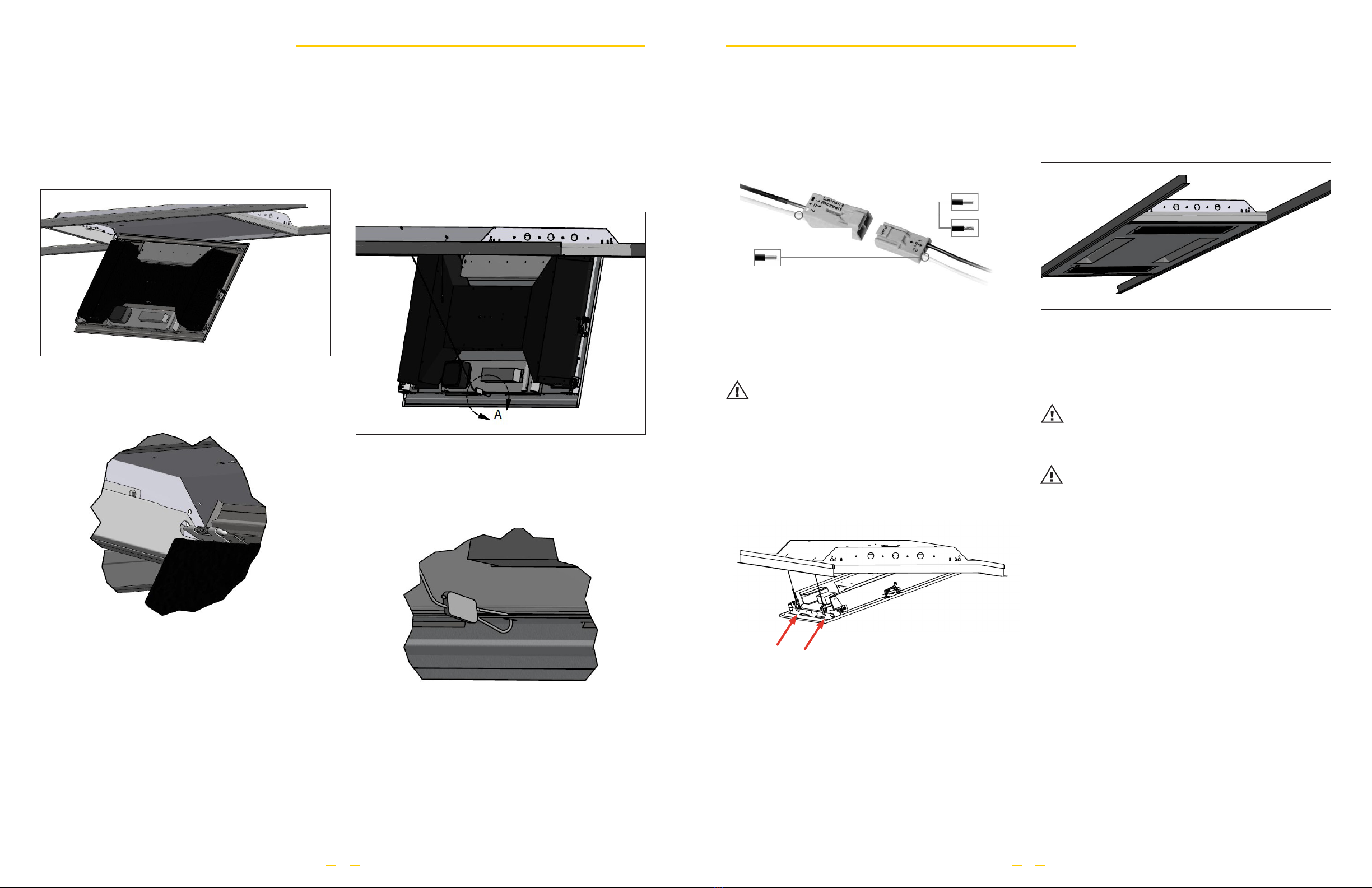
10. Connect AC Line and Neutral to Healthe Air Retrot xture with
provided luminaire disconnect as shown. (See Fig. 10)
11. Place warning label found in package on the xture.
12. Attach the two safety cables. (See Fig. 12)
13. Lift up Healthe Air Retrot xture and close it. You should hear the
latches ‘click’ closed. Press up in the latching corners to ensure both
latches are secured. (See Fig. 13)
Fig. 12
Fig. 13
NOTE: Warning label with the following warning shall be placed
on to the xture in a location which is readily visible by the user
during and after installation: ”Caution: Risk of injury or damage:
This luminaire has been modied and can no longer operate a
uorescent lamp. Use only Healthe® Air Retrot Kit or contact
manufacturer for more information.”
NOTE: Ensure all wires are tied up and don’t get pinched when
closing the kit.
NOTE: Ensure that the hanging cables do not get sandwiched
between the retrot xture and the mounting brackets.
Fig. 10
These PUSHWIRE male connectors
clamp the following copper conductors:
solid
These PUSHWIRE female connectors
clamp the following copper conductors: stranded
solid
Installation GuideInstallation Guide
Healthe Inc. |3905 W Eau Gallie blvd, Suite 101, Melbourne, FL 32941 |877.999.5742 |healtheinc.com
6
Healthe Inc. |3905 W Eau Gallie blvd, Suite 101, Melbourne, FL 32941 |877.999.5742 |healtheinc.com
7
Setup & Operations Guide
HEALTHE AIR CONTROL SCHEMES
To take advantage of all the features, we encourage using the SunTrac Pro App, available for iOS from Apple App
Store to commission and setup the Healthe Air.The SunTrac Double Rocker Wireless Switch (sold separately)
can also offer localized control and adjustment options for illumination and sanitization functions.
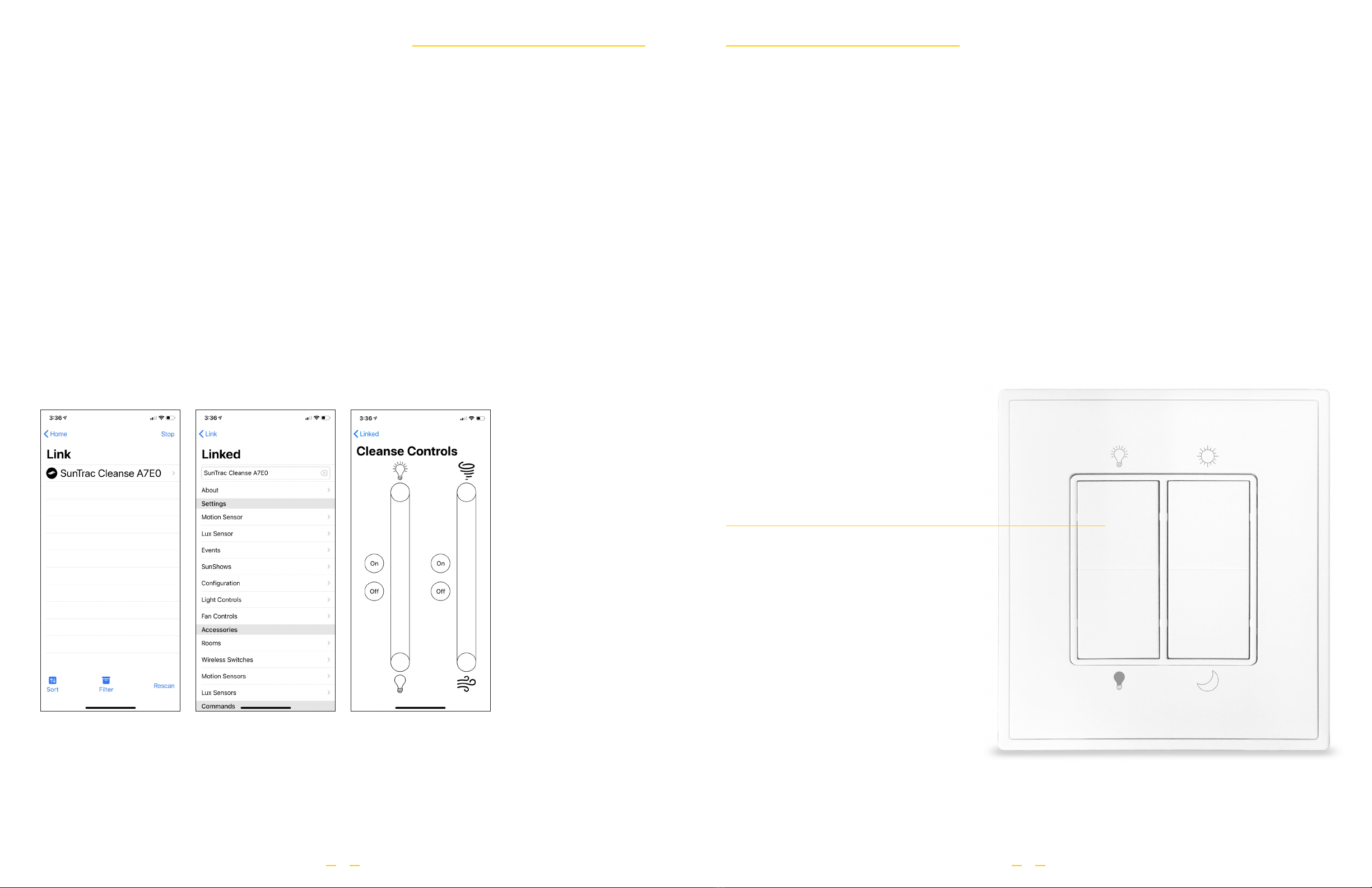
COMMISSIONING AND SETUP WITH SUNTRAC PRO APP
1. Open the SunTrac Pro App. If you do not have the App, please download it from the Apple App Store.
2. Once the App is open, apply power to the Healthe Air.
3. Start pairing process by selecting "LINK" on the App. A scan will be performed and the "Cleanse" will appear
on the list (Fig 1). If device is not found, select "RESCAN" to repeat scan for new device.
4. Select Cleanse from LINK list and follow the remaining App instructions until pairing is complete. Once pairing
is complete,, it will appear LINKED with access to advanced controls (Fig 2).
5. Once paired, select "ABOUT" to verify latest rmware is installed. Select "UPDATE" to update the rmware if
available. Note: "UPDATE" button will only be enabled if a new rmware is available.
6. For sanitization and illumination control, select "CLEANSE CONTROL" and adjust to desired settings (Fig 3).
Fig 1 Fig 3Fig 2
CONNECTING SUNTRAC DOUBLE ROCKER
WIRELESS SWITCH TO HEALTHE AIR
1.The SunTrac Double Rocker Wireless Switch must be paired with the Healthe Air.
2. Perform the following on the SunTrac Double Rocker Wireless Switch to enter pairing mode
a.Tap and hold Upper Left button down for 10 seconds and release.
b.Tap and release Upper Left button.
c.Tap and hold the Upper Left button for another 10 seconds and release
d.Wireless Switch is now in pairing mode.
3.Turn on the Healthe Air(s) and tap once on the Upper Left button of the Wireless Switch to pair.
4. The visible light of the Healthe Air will ash when pairing is successful. Press any button on the switch to exit
pairing mode.
5.The Healthe Air is now paired with the Wireless Switch to allow control of both sanitization and illumination.
Please refer to the SunTrac Double Rocker Wireless Switch Reference Guide for control instructions.
Setup & Operations Guide
1.Tap & Hold for 10 seconds and release
2. 1x Tap
3.Tap & Hold for another 10 seconds and release
4. Switch is now in pairing mode
Healthe Inc. |3905 W Eau Gallie blvd, Suite 101, Melbourne, FL 32941 |877.999.5742 |healtheinc.com
8
Healthe Inc. |3905 W Eau Gallie blvd, Suite 101, Melbourne, FL 32941 |877.999.5742 |healtheinc.com
9
SUNTRAC WIRELESS SWITCH REFERENCE GUIDE
FOR HEALTHE AIR
1x Tap: Light On
Tap & Hold: Increase Intensity
1x Tap: Light Off
Tap & Hold: Decrease Intensity
1x Tap Together: Sanitization/Fan On
Tap & HoldTogether: Increase Fan Speed
1x Tap Together: Sanitization/Fan Off
Tap & HoldTogether: Decrease Fan Speed
Setup & Operations Guide
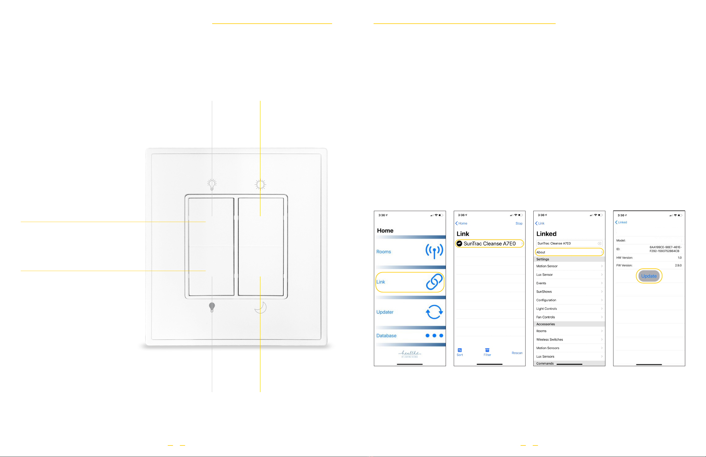
OVER-THE-AIR (OTA) FIRMWARE UPDATE
The Healthe Air may require periodic rmware updates to optimize performance, unlock new features as well
as x occasional software bugs. Firmware updates are conducted over-the-air and there are two methods to
perform the action.
SINGLE DEVICE FIRMWARE UPDATE METHOD
1. Ensure the Healthe Air is linked and paired to your SunTrac Pro App. Please refer to “Commissioning and
Setup” section for instructions.
2. Open the SunTrac Pro App and tap "LINK" to see the list of paired Healthe Air. (Fig 1)
3. Select the device to view details. (Fig 2)
4. Tap "ABOUT" to view information regarding current rmware installed. (Fig 3)
5. If new rmware is available, tap "UPDATE" to start the rmware update process. Note: "UPDATE" button will
ONLY be enabled if a new rmware is available. (Fig 4)
6. Once progress bar reaches end, the update is complete. Follow on screen instructions and return to main
menu.
Firmware Update
Fig 2Fig 1 Fig 4Fig 3
SunTrac®Cleanse A7E0
SunTrac®Cleanse
Healthe Inc. |3905 W Eau Gallie blvd, Suite 101, Melbourne, FL 32941 |877.999.5742 |healtheinc.com
10
Healthe Inc. |3905 W Eau Gallie blvd, Suite 101, Melbourne, FL 32941 |877.999.5742 |healtheinc.com
11
Service Guide
Routine maintenance to key components of the Cleanse Retrot Air will
help to sustain peak performance and minimize downtime. For optimal
performance, HEPA/Charcoal lter should be inspected monthly and
is recommended to be replaced every six months. For UV LED, it is
recommended to replace after every 2,000 hours of service as indicated
by a solid yellow indicator light on the Air.
REPLACING THE HEPA/CHARCOAL FILTER
1.Turn off the Healthe Air via the switch on the front (Fig 1).
2. Locate the screen closest to the power switch. Remove the two screws
and the screen (Fig 2).
3. Once the screen is removed, bend the tabs on the side of the lter to
release and remove it (Fig 3).
4. Install new lter.
5. Reinstall screen with the corresponding 2 screws (Fig 2).
6.Turn on the power via the switch on the front of the unit (Fig 1).
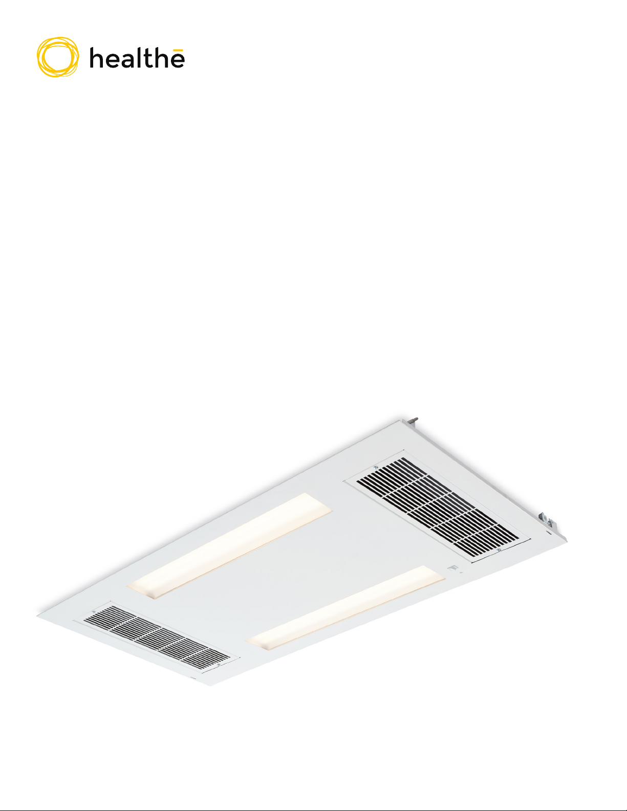
REPLACING THE UV LED SANITIZATION MODULE
1.Turn off the Healthe Air via the switch on the front (Fig 1).
2. Identify the two slots on the edge of the Air next to the screens. With a
hand on the Air, insert a at head screwdriver into the slot to trigger the
latch release (Fig 4).
3. Once released, carefully let the Air swing down on its hinges for about 8
inches while supported by two safety cables (Fig 5).
4. Detach the two links connecting the safety cable to the Air and carefully
let the Air swing down the rest of the way on its hinges (Fig 5 A/B).
5. Disconnect the quick connect of the UV LED module and remove the
six screws to release the metal cover exposing the UV LED module
behind it (Fig 6).
6. Remove existing UV LED module and install the new UV LED onto the
metal cover using included double-side tape.
7. Attach metal cover to Air with the six corresponding screws and
connect the quick connect (Fig 6).
8. Swing Air back towards housing to reattach the safety cable links (Fig 5,
5A/B).
9. Once the safety cables are attached, push Air back into housing until a
"CLICK" is heard, indicating the Air is fully reinstalled and secured.
10.Turn on the power using the switch on the front of the unit (Fig 1).
Fig 3
Fig 2
Fig 5 5A
5B
Fig 1
Fig 4
Fig 6
Firmware Update
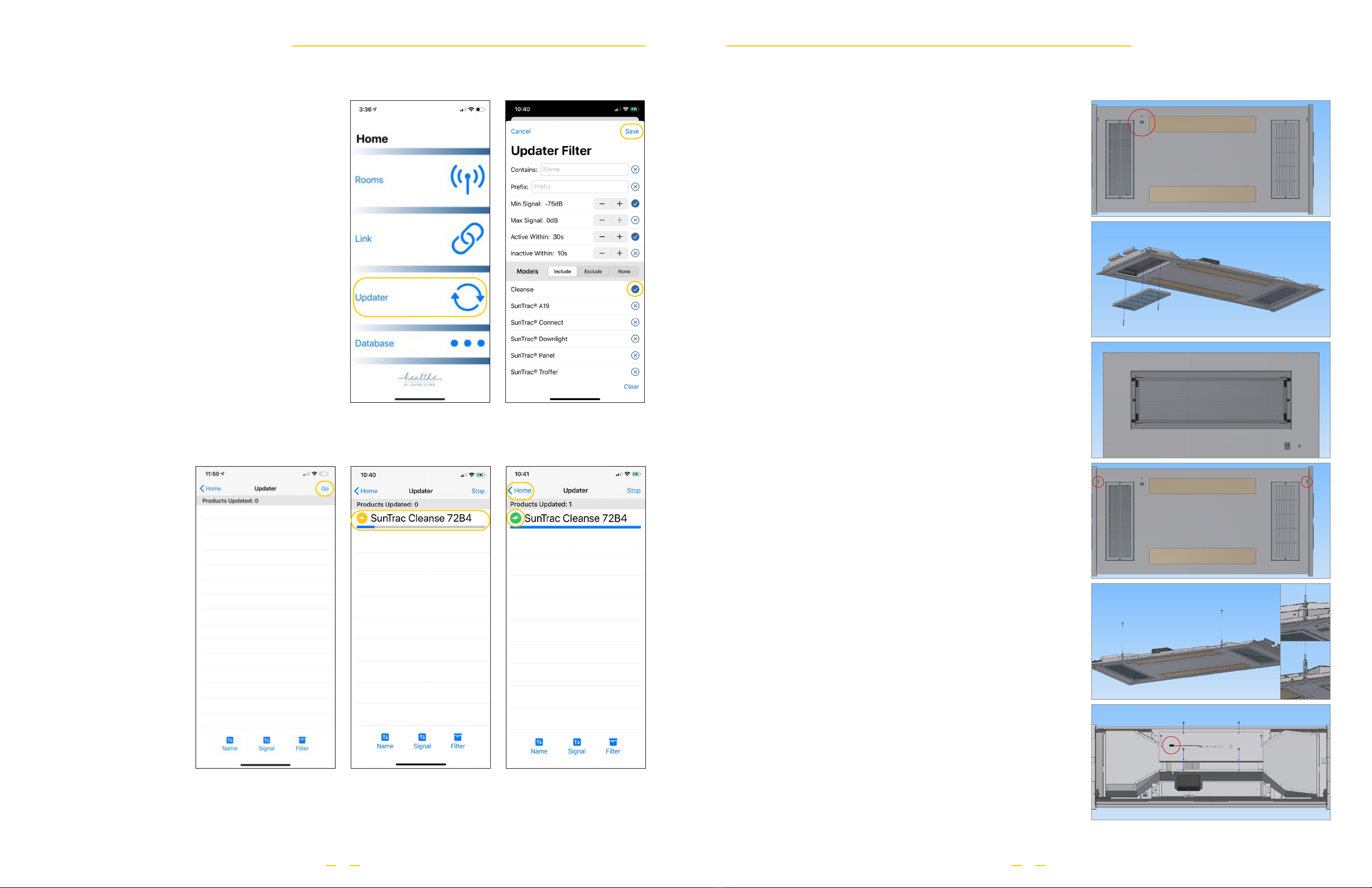
MULTIPLE DEVICE FIRMWARE
UPDATE METHOD
1. Ensure all Healthe Air devices are linked and
paired to your SunTrac Pro App. Please refer to
“Commissioning and Setup” section for instructions.
2. Open the SunTrac Pro App and tap "UPDATER" to
see the “UPDATER FILTER” (Fig 1)
3. Select “CLEANSE” under the “MODELS” section
and tap “SAVE”. (Fig 2)
4. Tap “GO” on the next screen to start scan and
automatically update rmware to all the Healthe Air.
(Fig 3)
5. Each device that requires a rmware update will
automatically start and progression bar will be
visible. (Fig 4)
6.The icon on the left will turn "green" once update
is complete. When updates are complete and all
devices show "green", tap on "HOME" to return to
main menu. (Fig 5)
Fig 3
Fig 2Fig 1
Fig 5Fig 4

©2020 Healthe Inc. All Rights Reserved.
Specications subject to change without notice.
DOC-00001-REV1
Healthe Inc.
3905 W Eau Gallie blvd, Suite 101, Melbourne, FL 32941
877.999.5742 | healtheinc.com
Before you begin to install Healthe® Air Retrot Kit, please read the entire installation manual guide carefully!
WARNING:This product must be installed in accordance with the applicable installation code by a person familiar with the construction and
operation of the product and the hazards involved.
WARNING:Only those open holes indicated in the photograph and/or drawings may be made or altered as a result of kit installation. Do not
leave any other open holes in an enclosure of wiring or electrical componenets.
WARNING:Risk of re or electric shock. The electrical rating of these products are 100–277V. The installer must determine whether they have
100–277V at the luminaire before installation.
WARNING: Risk of re or electric shock. Existing luminaire’s wiring, ballasts or other electrical parts may have been damaged prior to this
installation. Check enclosed wiring and components.
WARNING: Risk of re or electric shock. Healthe Air Retrot Kit installation requires knowledge of uorescent lighting luminaire’s electrical
systems. If not qualied, do not attempt installation. Contact a qualied electrician.
WARNING: Risk of re or electric shock. Install this product only in the luminaires that have the construction features and dimensions shown in
the photographs and/or drawings.
WARNING:To prevent wiring damage or abrasion, do not expose wiring to edges of sheet metal or other sharp objects.
WARNING: Risk of injury and damage. Must be installed by qualied licensed electrician. The existing troffer housing must be suspended from
structural members of the building above the ceiling grid. It is the responsibility of the installer to ensure that all materials (including existing
troffer housing), hardware, and building structural members used can bear and support the weight of Healthe Air (34 lbs) and that they meet all
applicable building and safety codes once installed.
DANGER: Risk of shock. Disconnect power before installation.
ATTENTION: Ce produit doit être installé conformément à l'installation applicable code par une personne familaire avec la construction et
l'utilisation du produit et les dangers impliqués.
ATTENTION: Seulement, les trous ouvertes indiquées dans la photographie et / ou les dessins peuvent etre modiés ou rendus de l'installation
du kit. Ne conceptionz pas tout autre ouvert trous dans un encre de câblage ou de composants électriques.
ATTENTION: Risque d'incendie ou de choc électriques. La puissance électriques de ces produit est de 100–277V. L'installateur doit déterminer
s'ils ont 100–277V sur le luminaire avant l'installation.
ATTENTION: Risque d'incendie ou de choc électriques. Le câblage du luminaire existant, les ballasts ou d'autres pièces électriques peuvent avoir
été endommagés avant cette installation. Vériez le câblage et les composants inclus.
ATTENTION: Risque d'incendie ou de choc électriques. L'installation de Healthe Air Retrot Kit nêcessite des connaissances. Des systèmes
électriques du luminaire ourescent. Si ce n'est pas qualié, n'essayez pas d'installer. Contactez un électricien qualié.
ATTENTION: Risque d'incendie ou de choc électriques. Installez ce produit uniquement dans les photoraphies et / ou les dessins.
ATTENTION: Pour éviter les dommages causés par le câblage ou l'abrasion, ne pas exposer le câblage aux bods de la tôle ou autre objects
tranchants.
ATTENTION: Risque de blessures et de dommages.Doit être installé par un électricien qualié et agréé. Le logement du troffer existant doit être
suspendu aux éléments de structure du bâtiment au-dessus de la grille du plafond. Il est la responsabilité de l'installateur de s'assurer que tous
les matériaux (y compris le logement de troffer existant), la quincaillerie et les éléments de structure du bâtiment utilisés peuvent supporter et
soutenir le poids du Healthe Air (34 lbs) et qu'ils respectent tous les codes de construction et les sécurité applicables une fois installé.
DANGER: Risque de choc. Deconnecter la puissance avant l'installation.
Safety Information
Table of contents
Popular Water Filtration System manuals by other brands


JRC
JRC NSVA352 manual

Plymovent
Plymovent MDB GO Installation and user manual

Reflex
Reflex Fillsoft operating instructions

Filtration Group
Filtration Group Pi 211 manual

amiad
amiad TEQUATIC PLUS F-150 C Series Installation & operation manual

Donaldson Torit
Donaldson Torit 684LP Installation, operation and maintenance manual