FSI PASS-1600ISO User manual

Isolation Systems Inc
Operation and Maintenance Manual PASS-1600ISO
2 October, 2020
Isolation Systems Inc
1
889 Erie Ave, North Tonwanda NY, 14120
PASS-1600ISO
Air Filtration System
Operation and Maintenance Manual
Isolation Systems Inc.
889 ERIE AVENUE, NORTH TONAWANDA NY 14120
(716) 694-6390 Fax (716) 694-3026
Email: SALES@ISOSYSINC.COM website: www.ISOSYSINC.COM
Revised: 2 October, 2020

Isolation Systems Inc
Operation and Maintenance Manual PASS-1600ISO
2 October, 2020
Isolation Systems Inc
2
889 Erie Ave, North Tonwanda NY, 14120
Do Not Use for Flammable Gas or Vapors.
This unit can ONLY be safely used after the room is ventilated to remove
flammable gases or vapors and certified by authorities to be below the
lower explosion limit or flash point.
Do not use for: coal dust, grain elevator and other explosive or flammable
dusts until professionals certify it is safe to do so.
•Failure to use a grounded electrical outlet could result in anelectrocution
injury.
•Disconnect unit from electrical outlet before performing any service or
maintenance.
•Never look at the UV lamps. Ultraviolet radiation may cause serious
damage to the eyes.
•Failure to properly select and replace filters can result in injury.
•Red indicator light blinks and auditory alarm signals when a filter is
blocked
•Do not install or operate this equipment before reading and understanding
this entire manual

Isolation Systems Inc
Operation and Maintenance Manual PASS-1600ISO
2 October, 2020
Isolation Systems Inc
3
889 Erie Ave, North Tonwanda NY, 14120
TABLE OF CONTENTS
SECTION PAGE
1.0
Introduction 4
1.1
Overview 4
1.2
Specifications 5
2.0 Installation and Operation 6
2.1
Preparation, Installation
6
2.2
Operation 6
2.3
Controls and Displays 7
2.4
Adjusting for Differential Pressure 10
`
2.5
Example Configurations
11
3.0 Disposal / Sanitizing / Decontamination 14
4.0 Maintenance (Scheduled and Unscheduled) 14
4.1. Access to the Pre-filters, HEPA Filter, and UV lamps 15
4.2 Removal of UV lamps in the front UV lamp bracket
15
4.3 Removal of the HEPA Filter 16
4.4 Replacement of the Rear UV lamps 17
4.5 Re-installation Steps 17
4.6 Repair/Replacement of Ducts 18
4.7 Replacement of Ballasts
18
5.0 Troubleshooting 19
6.0 Customer Service 19
7.0 Recommended Spare Parts and Consumables 20
8.0 Abbreviations 20
9.0 Wiring Diagrams 20
10.0 Control Cabinet Components 23
10.1 Control Circuit Card Assemblies 24
11.0 Labels 25
12.0 Warranty 26

Isolation Systems Inc
Operation and Maintenance Manual PASS-1600ISO
2 October, 2020
Isolation Systems Inc
4
889 Erie Ave, North Tonwanda NY, 14120
AIRFLOW
Portable Air Safety Systems (PASS) 1600ISO
1.0
Introduction
1.1
Overview
The Isolations Systems Inc. Portable Air Safety Systems (PASS) 1600ISO unit provides
portable air filtration for standalone use in any area requiring enhanced air quality.
The PASS-1600ISO is capable of providing the proper interior environmental air quality as
outlined by AIA, ANSI/ASHRAE Standard 62.1-2019, Ventilation for Acceptable Indoor Air
Quality and the Centers for Disease Control (CDC) guidance for air changes per hour (ACH).
The continuous filtering of the air protects the area from biological contamination.
The PASS-1600ISO patented filtration configuration incorporates two banks of germicidal
ultraviolet lamps directed at and irradiating each side of a HEPA filter. The patented technology
serves three purposes. First, it irradiates and kills the microbial airborne contamination that are
captured and contained on the HEPA filter media surface. The resulting effect is the HEPA filter
does not become an incubator for the growth of infectious agents that can spread infection by
secondary aerosolization. The second advantage of this configuration is the HEPA filter itself.
The filter is a micro fiberglass HEPA filter that is rated at a 99.97% efficiency removal rate for all
particles >0.1 microns. This includes all fungi, bacteria, and most viruses. Finally, very small
viruses >0.01 micron in diameter that could work their way through the HEPA instead are
irradiated with germicidal UV radiation. The residual time of the small virus being irradiated is
several orders longer than required to make the viruses non-viable.
FILTRATION ASSEMBLIES AND
CONFIGURATION
UVC
UVC
BLOWER
LAMP
HEPA
LAMP
&
BANK
BANK
CONTROL
CIRCUITS
Pre-HEPA UV-C Lamp Bank
Post-HEPA UV-C Lamp Bank
HEPA Filter Installed
HEPA Filter Removed

Isolation Systems Inc
Operation and Maintenance Manual PASS-1600ISO
2 October, 2020
Isolation Systems Inc
5
889 Erie Ave, North Tonwanda NY, 14120
1.2
Specifications MODEL: PASS-1600ISO
Dimensions 36.5” H x 18.5”W x 41.0”L
Weight
236 lbs
Power 115 VAC, 11.5 Amps, 60Hz, 1322 Watts,
Power Cord
12" 115VAC 3-pring cord (NEMA 5-15-P)
Airflow Capacity/Ports 0 to 1600 cfm, Electronic Speed Control
2 inlets, 2 outlets with adjustable dampers for flow control, 14” and 10”
Filter: High Capacity HEPA 24” T x 18” W x 11.5” D – Deep “V” Filter, 99.99% @ 0.3 Microns
Replace after 8760 hours of runtime, or when filter pressure
reaches 1.6 in WC
Optional Prefilter Carbon Poly Media Prefilter 24” H x 18” W x 2” D
UV lamps Front bank (PRE-HEPA) Four (4) lamps on removable frame
Rear bank (POST HEPA) Five (5) lamps on fixed frame
Bulb Intensity: 120 Microwatts/CM2
Wavelength: 254NM Germicidal
Displays and alarms Visual and Audio Alarm on Controller to indicate:
-HEPA Filter replacement
-Area Pressure Failure Controls
Controls Airflow is continuously adjustable via a rotary switch located next to
run-hour meter
Differential pressure dampers: continuous adjustment from negative
to positive differential pressure
Cabinet/Portability 16 Gauge Steel, Powder Coated
Wheels: Four 5" soft tread non marking solid tires, front locking

Isolation Systems Inc
Operation and Maintenance Manual PASS-1600ISO
2 October, 2020
Isolation Systems Inc
6
889 Erie Ave, North Tonwanda NY, 14120
2.0
Installation and Operation
Upon powering the unit, the blower and UV lamps will be automatically activated. NO NOT power
the unit (plug the unit into 110VAC) until the unit air ducts have been connected and enclosure
panels are closed to eliminate potential of Ultraviolet Light exposure.
2.1
Preparation and Installation
NOTE: Read the entire manual prior to performing paragraph "2.1. Preparation."
2.1.1 Move the unit to the desired location.
2.1.2 Lock the two locking wheels of the PASS unit.
2.1.3 Inspect the unit and ducts for any damage that could affect safety or function as well
inspect cleanliness. NOTE: The intake duct requires specific consideration as it may have been
exposed to unfiltered air and containments during previous use(s).
2.1.4 Unlock the filter section by rotating the nine (9) fasteners with
a coin or standard screwdriver 1/4 turn counterclockwise.
2.1.5 Open the compartment hinged panel.
2.1.6 Ensure that a fresh HEPA filter is in place and with the airflow
arrow pointing toward the outflow end of the unit.
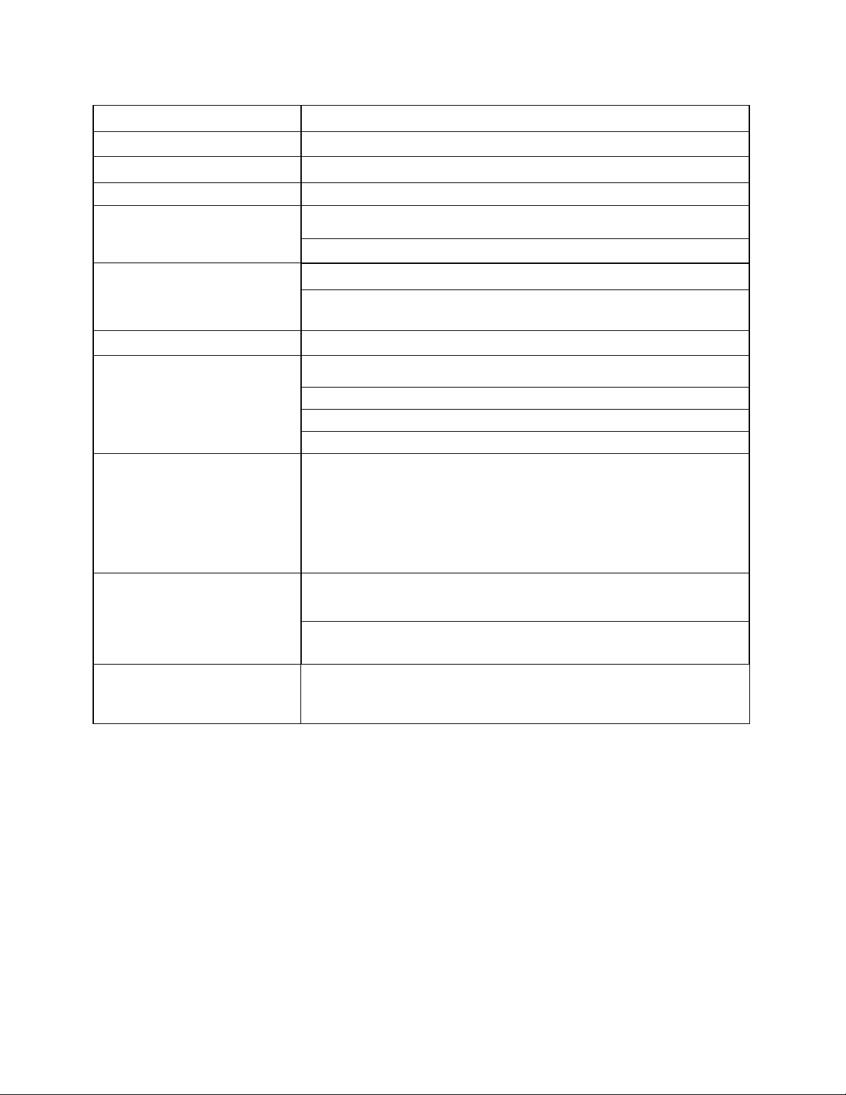
2.1.7 Inspect to ensure that the UV lamps are in place and the
"front bank" electrical plug is connected (noted by orange circle)
2.1.8 Close the hinged filter panel, and lock the six (6) fasteners with a coin or standard
screwdriver one-quarter turn clockwise.
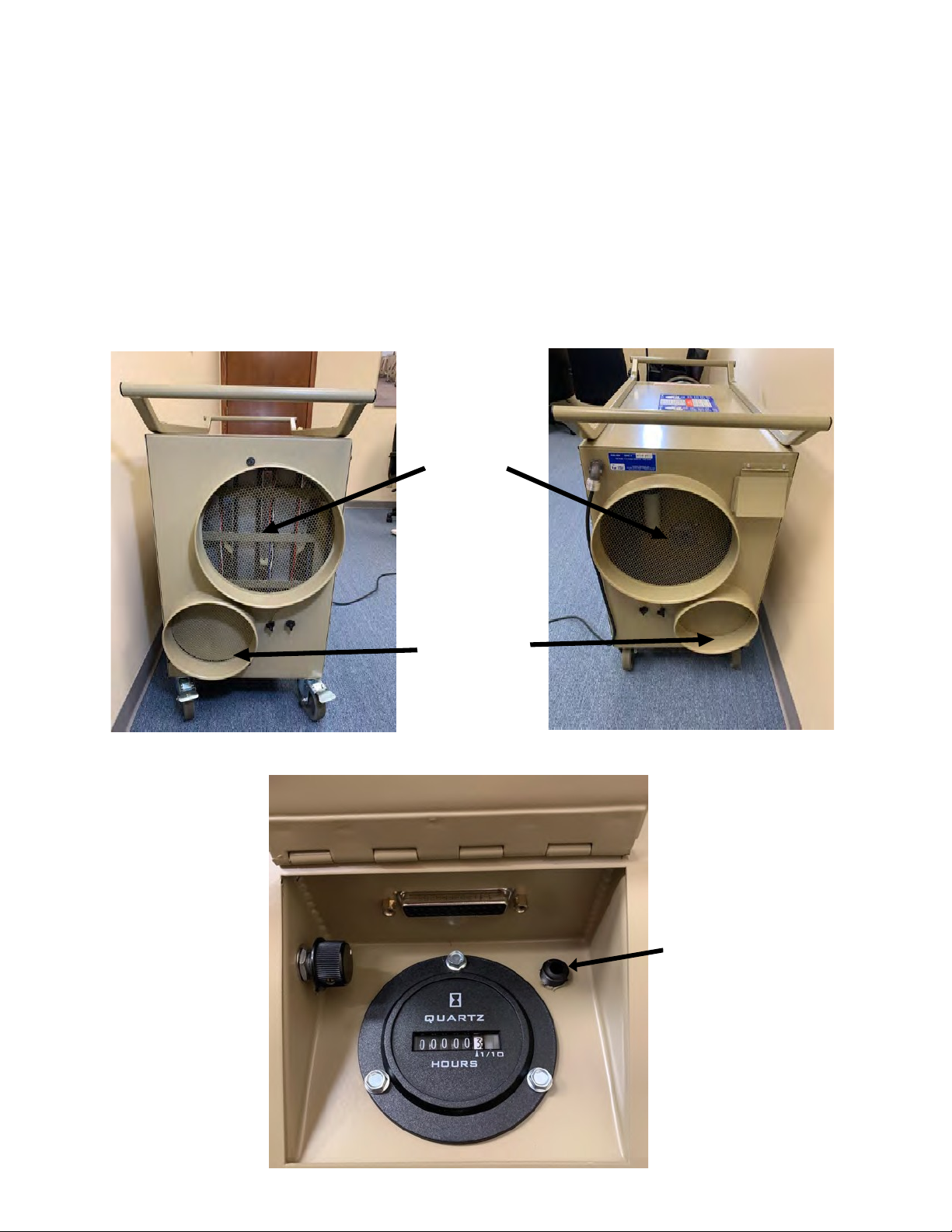
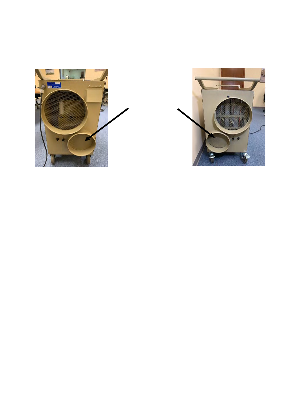
2.1.9 Install ductwork based on desired operation mode.
2.1.10 Connect controller to PASS unit (under hinged protective cover) and position
controller inside the shelter/facility.
2.2. Operation
2.2.1 Plug-in unit power cord. As soon as power is supplied the unit will begin a self-test and
upon completion will indicate filter and room pressures or errors if faults were sensed.
2.2.1 Adjust CFM (airflow) as desired using adjustable knob next to run-hour meter.
AIRFLOW

Isolation Systems Inc
Operation and Maintenance Manual PASS-1600ISO
2 October, 2020
Isolation Systems Inc
7
889 Erie Ave, North Tonwanda NY, 14120
Air Duct Installation
2.3. Controls and Displays
2.3.1. Controller & Accessory Case
Located in a foam lined case shown below, the PASS Controller includes a multifunction
digital display, red fault alarm lamp, audio alarm and silence button. The controller
case also includes the controller cord, air pressure line and T-handle wrench.
2.3.2
Digital display
The two-line digital display serves several functions, including a display of the room differential
pressure and the filter differential pressure as well as error signals.
2.3.2.1 Controller Alarms
•A red indicator lamp next to the digital display will blink when a fault is detected and
shown in the display.
•An audio alarm will sound when either a room monitor or filter differential pressure fault
occurs. It may be silenced by pressing the Audio Alarm Cancel button.
•The Audio Alarm Cancel button also serves as an override of the differential pressure
failure alarm to allow the unit to operate in the recirculation mode.

Isolation Systems Inc
Operation and Maintenance Manual PASS-1600ISO
2 October, 2020
Isolation Systems Inc
8
889 Erie Ave, North Tonwanda NY, 14120
2.2.3 Airflow Configuration and Controls
The PASS-1600ISO has two ports on each of the intake and exhaust ends of the unit. This
allows a number of configurations for the removal and replacement of room air.
•The smaller ports create the negative or positive pressure differential in the treated room.
•The larger ports provide recirculation of filtered room air.
•CFM is adjusted via rotary knob next to run-hour meter.
Primary
Circulation
Ports
Small Ports
Hinged Protective Cover
(*See image below*)
Pre-filter Air Pressure
Sensor Intake
Controller
Connection
Airflow /CFM
Adjustment knob
Run-Hour Meter

Isolation Systems Inc
Operation and Maintenance Manual PASS-1600ISO
2 October, 2020
Isolation Systems Inc
9
889 Erie Ave, North Tonwanda NY, 14120
2.2.3.2 Set the two (2) airflow dampers. The dampers
are secured in position by three (3) wing nuts. Loosen
the wing nuts to allow the damper to rotate. Re-tighten
the wing nuts after repositioning the dampers.
*NOTE: The foam tape seal on the damper may stick
when stored or unused for long durations. If the
damper does not move freely after the three wing nuts
are loosened, insert a screwdriver through a screen
hole on the small port and push straight inward with
light pressure against the damper. Gradually increase
pressure until you observe the seal is freed as it pops
loose.
Instructions for adjusting the dampers are also on the
unit.
2.2.4 Room Pressure Sensor
•If the unit is not located in the treated room, attach the 3/16 inch diameter tubing to the
upper air sampling port and extend it into the room.
•The lower air sampling port provides pressure information for automatic filter pressure
differential monitoring and remains uncovered.
Three (3) wing nuts to loosen or
tighten damper.
*Push against damper
through screen hole
here*

Isolation Systems Inc
Operation and Maintenance Manual PASS-1600ISO
2 October, 2020
Isolation Systems Inc
10
889 Erie Ave, North Tonwanda NY, 14120
2.4
Adjusting for Differential Pressure
2.4.1 For a neutral pressure application (recirculation only), the dampers on both the exhaust
and intake sides should be lowered to fully cover the smaller ports. The larger ports will be
fully uncovered to provide circulation at neutral pressure.
Small Ports fully
covered by
dampers for
Neutral Pressure
(Recirculation Only)
Exhaust End Intake End
Important. For recirculation mode the room pressure fault alert must be overridden. Press the
Audio Alarm Cancel button on the Display Panel for 5 seconds to cancel the pressure fault
alert. An R will appear in the Digital Display next to the Room Pressure to indicate operation is
in the Recirculation mode.
2.4.2 For a negative pressure application, open the air flow damper on the smaller port on the
EXHAUST end until about 1/3 open. Fully close the intake side’s smaller port damper.
2.4.3 For a positive pressure application, open the air flow damper on the smaller port on the
INTAKE end until about 1/3 open. Fully close the exhaust side’s smaller port damper.
•Attach the air supply and return ducting according to your selected configuration (see
examples below).
•Plug in the unit, turn the power switch to ON, and adjust the blower speed control for the
desired airflow (0 to 1600 CFM).
•Observe the pressure reading on the digital display and readjust the damper to achieve
the desired pressure differential. If the desired pressure differential cannot be achieved
even with a fully opened damper, increase the blower speed and repeat damper position
adjustment.
•The CDC recommended differential pressure is > 0.01 inches WC.
•When setup is complete, monitor the digital display for proper operating parameters and
for error alerts.

Isolation Systems Inc
Operation and Maintenance Manual PASS-1600ISO
2 October, 2020
Isolation Systems Inc
11
889 Erie Ave, North Tonwanda NY, 14120
2.5
Example Configurations
The PASS-1600ISO Negative Pressure
Shelter Example
The unit is placed outside the Isolation
shelter, the large air "intake" duct is
connected to the shelter duct port. A
small intake duct is supplied to the anti-
room and provides a slight negative
pressure to the ante-room.
The large exhaust duct is routed from
the PASS exhaust and is vented to the
outside to create negative pressure for
the room.
NOTE: Ducts not shown are not connected
Large Intake Duct
Large Exhaust Duct
Small Intake Duct
Small Exhaust
PASS1600ISO
Controller/Pressure Tube
Air Flow
INTAKE
EXHAUST
Ante-room
Intake
Controller
Exhaust
Unit Inside Shelter
Negative Pressure with Ante-room
Set-up
Large Intake: Patient Room, No Duct Small
Intake: Ducted to Ante-room
Large Exhaust: Patient Room, No Duct
Small Exhaust: Ducted outside
Dampers: Exhaust 1/3 open, Intake closed
Controller: Pressure tube outside shelter
Room

Isolation Systems Inc
Operation and Maintenance Manual PASS-1600ISO
2 October, 2020
Isolation Systems Inc
12
889 Erie Ave, North Tonwanda NY, 14120
Exhaust
Intake
Ante-room
Controller
Unit Outside Shelter
Negative Pressure with Ante-room
Set-up
Large Intake: Ducted to Patient Room
Small Intake: Ducted to Ante-room
Large Exhaust: Ducted to Patient Room
Small Exhaust: No Duct
Dampers: Exhaust 1/3 open, Intake closed
Controller: Pressure tube outside shelter
Room
Intake
Controller
Exhaust
Unit Inside Shelter
Negative Pressure
Set-up
Large Intake: Patient Room, No Duct
Small Intake: Ducted to Ante-room
Large Exhaust: Patient Room, No Duct
Small Exhaust: Ducted outside
Dampers: Exhaust 1/3 open, Intake closed
Controller: Pressure tube outside shelter
Room
Exhaust
Intake
Controller
Unit Outside Shelter
Negative Pressure
Set-up
Large Intake: Ducted to Patient Room Small
Intake: Ducted to Ante-room
Large Exhaust: Ducted to Patient Room
Small Exhaust: No Duct
Dampers: Exhaust 1/3 open, Intake closed
Controller: Pressure tube outside shelter
Room

Isolation Systems Inc
Operation and Maintenance Manual PASS-1600ISO
2 October, 2020
Isolation Systems Inc
13
889 Erie Ave, North Tonwanda NY, 14120
Intake
Controller
Exhaust
Set-up
Large Intake: Patient Room, No Duct
Small Intake: Ducted to
Ante-room
Large Exhaust: Patient Room, No Duct
Small Exhaust: Ducted outside
Dampers: Intake 1/3 open, Exhaust closed
Controller: Pressure tube outside shelter
Unit Inside Shelter
Positive Pressure
Room
Exhaust
Intake
Controller
Unit Outside Shelter
Positive Pressure
Set-up
Large Intake: Ducted to Patient Room Small
Intake: Ducted to Ante-room
Large Exhaust: Ducted to Patient Room
Small Exhaust: No Duct
Dampers: Intake 1/3 open, Exhaust closed
Controller: Pressure tube outside shelter
Room
Intake
Controller
Exhaust
Unit Inside Shelter
Air Filtration/Circulation
Set-up
Large Intake: Patient Room, No Duct
Small Intake: Ducted to Ante-room
Large Exhaust: Patient Room, No Duct
Small Exhaust: Ducted outside
Dampers: Closed
Controller: Alarm Disabled
Room

Isolation Systems Inc
Operation and Maintenance Manual PASS-1600ISO
2 October, 2020
Isolation Systems Inc
14
889 Erie Ave, North Tonwanda NY, 14120
3.0 Disposal / Sanitizing / Decontamination
Standard Procedures
3.1 Handle any contaminated materials in accordance with your institution’s or agency’s
regulations.
3.2 If the Unit or any materials can be sanitized or decontaminated, follow your institution’s or
agency’s regulations and procedures.
3.3 Dispose of all contaminated materials or equipment in accordance with your institution’s or
agency’s regulations and procedures. Dispose of HEPA filters when the filter pressure is 1.6
in WC, or no less often than 8760 hours of run time or annually as is provided with your
service contract.
4.0 Maintenance (Scheduled and Unscheduled)
WARNING! Only a trained, authorized maintenance person should access the filter
compartment. Only a trained, authorized technician should access elsewhere.
Tools required:
•Standard screwdriver for access to filter cabinet
•5/16 nut driver for access to electrical cabinet.
•3/16-inch Allen wrench
Before any maintenance procedure, disconnect all power from the unit. Power to the unit will
result in dangerous electrical contact and exposure to dangerous UV radiation. For any
service requiring power to the UV lamps, you must use safety glasses rated for UV protection
and ensure that no one without UV rated safety glasses can be exposed to the radiation.
Access to the filter compartment may expose biological
contaminated waste materials. Wear PPE as required and
be prepared to “red bag” waste that is removed.

Isolation Systems Inc
Operation and Maintenance Manual PASS-1600ISO
2 October, 2020
Isolation Systems Inc
15
889 Erie Ave, North Tonwanda NY, 14120
4.1. Access to the Pre-filters, HEPA Filter, and UV lamps
4.1.1 Unlock the filter section by rotating the nine (9) fasteners with a
standard screwdriver one-quarter turn counterclockwise as shown in
paragraph 2.1.4
4.1.2 Open the hinged filter panel.
4.1.3 The internal assembly is held in place by pressure applied
against the pressure plate by two (2) set screws. The pressure plate is
also the bracket that holds the pre-filter.
4.1.4 To release the pressure plate, insert the T-handle wrench into one
of the access holes in the front face of the unit. Maneuver the wrench
until you feel it lock into the set screw. Turn the handle CCW to release
its pressure on the pressure plate. Insert the wrench into the other
access hole, engage the set screw, and turn the screw CCW to release
the pressure on the other end of the pressure plate.
4.1.5 Disconnect the electrical connector to the UV lamp bracket. The
connector is tucked in the upper right corner of the compartment and
shown in paragraph 4.2.1
4.1.6 Remove pre-filter from the front bracket/ pressure plate.
Dispose of pre-filter in accordance with your institution’s or agency’s
regulations and procedures. Insert a new pre-filter, as needed.
4.1.7 Slide the pressure plate from the compartment.
4.1.8 The front UV lamp bracket and the HEPA filter are now loosened
for removal.
4.2 Removal of UV lamps in the front UV lamp bracket
NOTICE. Never touch the UV lamps with your hands or any oily materials. This
will cause the lamp to lose efficiency or possibly break when next used. Always
use a clean cloth to handle a UV lamp.
NOTICE. Never touch a usable filter with your hands or any oily materials.
Always handle by the frame to avoid damage to the media and sealing surfaces.

Isolation Systems Inc
Operation and Maintenance Manual PASS-1600ISO
2 October, 2020
Isolation Systems Inc
16
889 Erie Ave, North Tonwanda NY, 14120
4.2.1 To remove the UV bracket, locate the electrical connection near the top of the bracket,
squeeze the two tabs on the long sides of the connector and pull the plastic halves of the
connector apart.
4.2.2 Lamps are removed by applying pressure in the direction of the spring loaded end
bracket until the other end of the lamp releases. Insert a new lamp by reversing the
procedure. The lamp shield is oriented away from the HEPA filter so that the lamp is fully
exposed to the filter.
4.3 Removal of the HEPA Filter
4.3.1 Slide the HEPA FILTER toward the end of the unit and carefully pull it out of the
compartment. If the Filter is to be discarded, carefully place it in an approved disposal bag.
HEPA INSTALLED HEPA REMOVED
(SIDE VIEW) PASS1600 with pre-filter,
Pressure plate and HEPA
filter removed
Front of UV lamp bracket
showing lamp shields.
Lamps are fully exposed to
the HEPA filter when
installed.

Isolation Systems Inc
Operation and Maintenance Manual PASS-1600ISO
2 October, 2020
Isolation Systems Inc
17
889 Erie Ave, North Tonwanda NY, 14120
4.4 Replacement of the Rear UV lamps
4.4.1 The rear UV lamp bracket holds five (5) lamps. These lamps
are replaced without removing the bracket.
4.4.2 Lamps are removed by applying pressure in the direction of
the spring loaded end bracket until the other end of the lamp
releases. Insert a new lamp by reversing the procedure. The lamp
shield is oriented away from the HEPA filter so that the lamp is fully
exposed to the filter.
4.5 Re-installation Steps (Assuming all components are removed from the compartment.)
4.5.1 Insert the HEPA filter.
4.5.1.1 Remove a new HEPA FILTER from its packaging or use the existing filter.
4.5.1.2 Inspect the filter for damage and that the sealing surface of the filter is not torn or
damaged.
WARNING! Note the airflow arrow on the label. Turn the filter so that the label is facing
up and the air flow arrow points toward the output end of the unit.
4.5.1.3 Slide the filter into the compartment so that its edges are evenly touching the sealing
surface in front of the rear UV lamp bracket. This edge will form a critical seal when tension is
re-applied.
4.5.2 Re-assemble the Front UV Lamp Bracket
4.5.2.1 Replace any lamps, as needed, according to Section 4.2. The lamp shield is oriented
away from the HEPA filter so that the lamp is fully exposed to the filter.
4.5.2.2 Insert the front UV lamp bracket into the compartment. Ensure the lamps face the HEPA
filter and the electrical connector wire can be brought around the pre-filter/ pressure plate.

Isolation Systems Inc
Operation and Maintenance Manual PASS-1600ISO
2 October, 2020
Isolation Systems Inc
18
889 Erie Ave, North Tonwanda NY, 14120
4.5.3 Insert the prefilter/pressure plate in front of the UV lamp bracket
so that the lip is toward you and overlaps the side of the UV lamp
bracket. Ensure that the plate does not pinch the electrical wire
coming from the top corner of the lamp bracket.
4.5.3.1 Reconnect the plastic electrical connector. The connector is
designed to prevent miss-orienting the halves. If the halves do not
mate, turn one of them around. Push the halves of the connector
together fully until the locking tabs are seated. Tuck the connector
into the top corner of the cabinet.
4.5.4 Tighten the tensioning set screws with the Allen wrench, alternating between sides to
ensure an even tension on the components. Tighten snugly. The HEPA filter seal should be
compressed to between ½ and ⅓ of its original size.
4.5.5 Close the lid and tighten the nine (9) quarter-turn fasteners.
4.6 Repair / Replacement of Ducts
If holes or tears are found, replace the duct or repair with duct tape. Ducts require sanitation
or replacement after use in a contaminated environments. Reminder, the air intake duct is
exposed to unfiltered air during initial operation.
4.7 Replacement of Ballasts
UV ballasts should be replaced if a lamp that is known to be good does not light.
NOTICE. Never touch the UV lamps with your hands or any oily materials. This will
cause the lamp to lose efficiency or possibly break when next used. Always use a
clean cloth to handle a UV lamp.
For UV lamp removal, see Sections 4.2 and 4.4
Ballasts are mounted next to their lamps on the UV lamp brackets.
UV LAMP BALLAST •Ballasts have four (4) quick-connect connections.
Press the corresponding tab while pulling on the wire
and the wire will release from the connector. Remove
all four (4) wires. Remove one of the nuts holding the
ballast to the shield and loosen the second nut.
Remove the ballast.
•Reverse the procedure to install new ballasts. Orient
the ballast the same as the removed ballast so the
wires are positioned according to the color code on
the connectors on the wires.
Lip

Isolation Systems Inc
Operation and Maintenance Manual PASS-1600ISO
2 October, 2020
Isolation Systems Inc
19
889 Erie Ave, North Tonwanda NY, 14120
5.0 Troubleshooting
Symptom
Indicates
Cause or Solution
Red indicator light
blinks
Indicates a pressure fault. Read display for causes
Auditory alarm sounds
Indicates obstructed airflow
Read display for causes
Display reads
FILTER FAILURE or
reading 0.000” WC
Indicates obstructed airflow, filter end of
life.
Check for airflow blockage.
Replace filter if needed.
Prefilter plugged up.
Manometer failure.
No HEPA filter installed.
Tubing blockage inside the
unit.
Display reads
Delta PR failure
Room monitoring failure.
Any reading between a Negative
pressure of 0.000 and –0.010 WC and a
Positive pressure of 0.000 and 0.010.
Pressure hose not
connected.
Hose connected to the
wrong port.
Kinked or blocked tubing.
Not enough airflow turn up
blower speed to create
more pressure + or -
Unit fails to operate /
miscellaneous Various faults not listed previously Contact Isolation Systems
Customer Support. If
recommended, check
fuses on control circuits
and replace as required.
6.0 Customer Service
Isolation Systems Inc.
889 ERIE AVENUE, NORTH TONAWANDA NY 14120
(716) 694-6390 Fax (716) 694-3026
Email: SALES@ISOSYSINC.COM website: www.ISOSYSINC.COM

Isolation Systems Inc
Operation and Maintenance Manual PASS-1600ISO
2 October, 2020
Isolation Systems Inc
20
889 Erie Ave, North Tonwanda NY, 14120
7.0 Recommended Spare Parts and Consumables
QUANTITY
Description
PART Number
1
HEPA filter
80016
5
UV Lamps
2107
2
UV Ballasts
2104
8.0 Abbreviations
ACH
Air Changes Per Hour
AIA
American Institute of Architects
ISO SYS
Isolation Systems Inc
BMS
Building Management System
CCW
Counterclockwise
CDC
Center for Disease Control
CW
Clockwise
HEPA
High Efficiency Particulate Air
μW
Microwatts
nm
Nanometers
PASS
Portable Air Safety System
PPE
Personal Protective Equipment
UV
Ultraviolet
WC
Water Column
9.0 Wiring Diagrams
Drawing 1) PASS-1600ISO Wiring Diagram
Drawing 2) Detail wiring of Impeller/ Blower and Speed Controller
Table of contents
Other FSI Water Filtration System manuals
Popular Water Filtration System manuals by other brands

ARKA
ARKA Aquatics Core MF500 Operation instructions

Aquaporin
Aquaporin ZERO Replacement guide

Sepura
Sepura SEP 120 ST installation manual

Grunbeck
Grunbeck GENODOS DME 6 Operation manual

Water Factory Systems
Water Factory Systems SQC3 Series owner's manual

Beko
Beko CLEARPOINT HP100S040 Instructions for installation and operation