LSC MDR-DIN User manual

RJ45 Sockets Push Fit Terminals
User Manual
LSC Control Systems
+61 3 9702 8000
info@lsccontrol.com
www.lsccontrol.com
Version 1
October 2020

MDR-DIN DMX Splitter
User Manual
Page 2
Disclaimer
LSC Control Systems Pty. Ltd. has a corporate policy of continuous improvement, covering
areas such as product design and documentation. To achieve this goal, we undertake to release
software updates for all products on a regular basis. In light of this policy, some detail contained
in this manual may not match the exact operation of your product. Information contained in this
manual is subject to change without notice.
In any event, LSC Control Systems Pty. Ltd. cannot be held liable for any direct, indirect, special,
incidental, or consequential damages or loss whatsoever (including, without limitation, damages
for loss of profits, business interruption, or other pecuniary loss) arising out the use or the inability
to use this product for its intended purpose as expressed by the manufacturer and in conjunction
with this user manual.
Servicing of this product is recommended to be carried out by LSC Control Systems Pty. Ltd. or
its authorized service agents. No liability will be accepted whatsoever for any loss or damage
caused by service, maintenance or repair by unauthorized personnel.
In addition, servicing by unauthorized personnel may void your warranty.
LSC Control Systems’ products must only be used for the purpose for which they were intended.
Whilst every care is taken in the preparation of this manual, LSC takes no responsibility for any
errors or omissions.
Copyright Notices
www.lsccontrol.com.au
Copyright © 2020 LSC Control Systems Pty. Ltd.
All rights reserved.
Contents of this manual, Copyright © 2020
All Trademarks referred to in this manual are the registered names of their respective owners.
The operating software of the Mantra Mini, the Mantra Editor and the contents of this manual
are copyright of LSC Control Systems Pty. Ltd. © 2020.
Contact Details
LSC Control Systems Pty. Ltd.
ABN 21 090 801 675
65-67 Discovery Road
Dandenong South, Victoria 3175 Australia
Tel: +61 3 9702 8000
Fax:+61 3 9768 2631
email: info@lsccontrol.com
web: www.lsccontrol.com

MDR-DIN DMX Splitter
User Manual
Page 3
Contents
1 Introduction ................................................................................................ 4
1.1 Overview ...................................................................................................................... 4
1.2 Models .......................................................................................................................... 4
1.3 Features ....................................................................................................................... 4
2 Installation .................................................................................................. 5
2.1 Installation .................................................................................................................... 5
2.2 DMX Cables ................................................................................................................. 5
2.3 Push-Fit Terminals ....................................................................................................... 6
2.4 DMX Pin Outs .............................................................................................................. 6
2.5 Operation ..................................................................................................................... 6
2.6 RDM Enable ................................................................................................................. 6
2.7 DMX Explained ............................................................................................................ 6
3 Compliance Statements ............................................................................. 7
4 Specifications ............................................................................................. 7

MDR-DIN DMX Splitter
User Manual
Page 4
1 Introduction
1.1 Overview
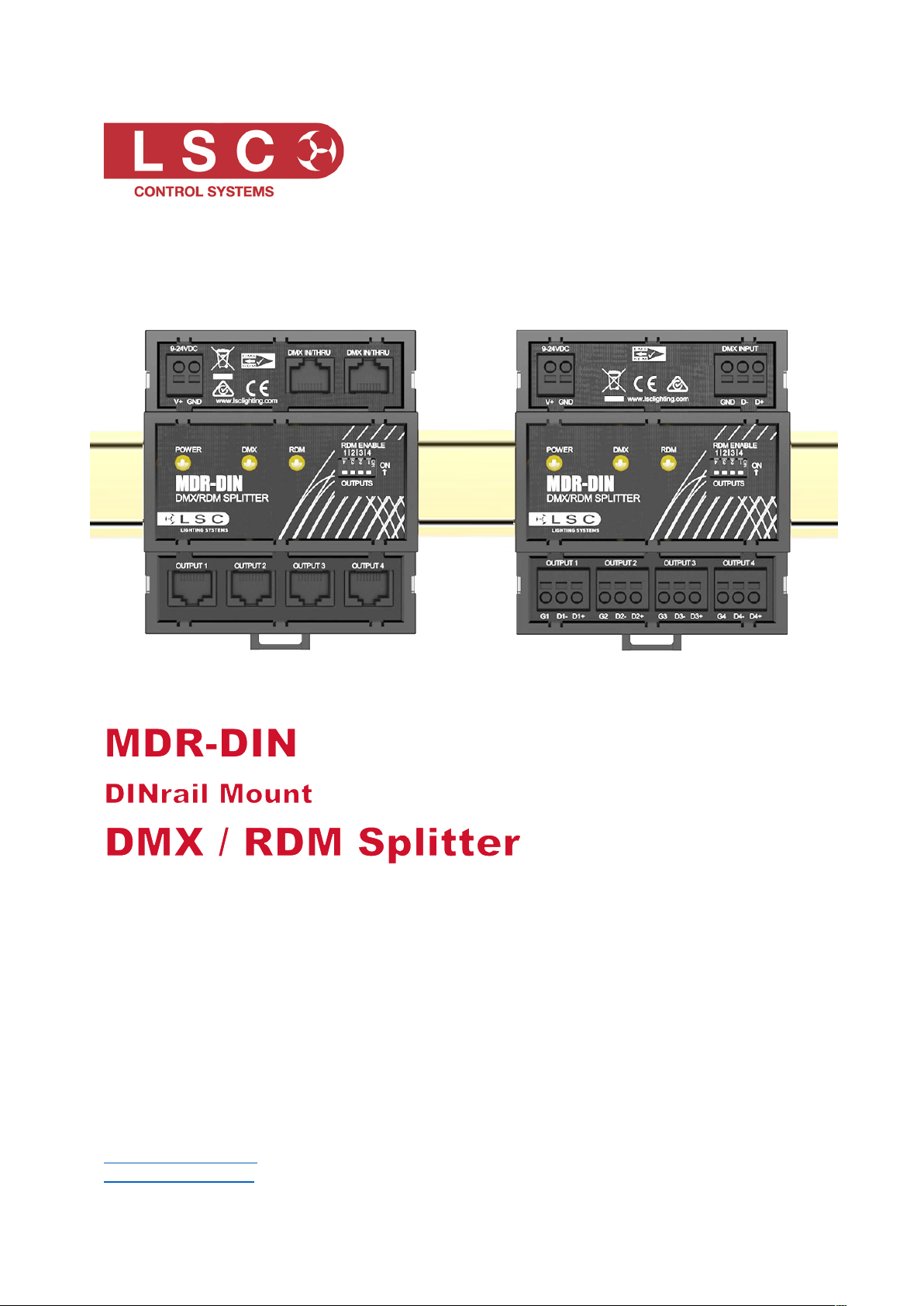
The MDR-DIN splitter is based on the successful range of MDR splitters. It is housed in a 5-
module wide DIN plastic enclosure designed to mount onto a standard TS-35 DIN rail as used
extensively in the electrical industry to mount circuit breakers and industrial control equipment.
The MDR-DIN splitter provides four individual outputs from one DMX/RDM input. Each output is
completely electrically isolated from the input and all other outputs, ensuring that voltage
differences and noise will not compromise your installation.
The MDR-DIN handles the management of RDM (Remote Device Management) signals across
its four outputs. RDM is an extension to the existing DMX standard and allows controllers to
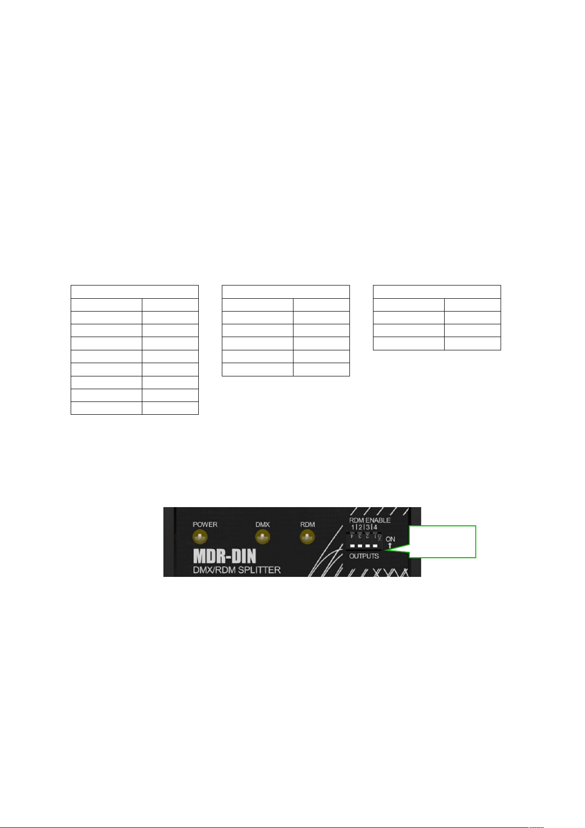
configure and monitor DMX based products. Unique to the MDR-DIN is the ability to individually
disable RDM on any of its outputs using the front-panel switches. While many devices now offer
RDM compatibility, there are still products available that do not perform correctly with RDM,
causing the DMX network to flicker or jam when RDM signals are present. The MDR-DIN
provides the ability to isolate these devices to one output by disabling the RDM, ensuring RDM
can be used successfully on the remaining ports.
With LSC’s companion product, Houston-X, the state of the RDM enabled switches can be
monitored remotely and a list of connected RDM devices can be reported including which output
each device is connected to. Houston X also allows MDR-DIN software to be updated via RDM,
so once it’s installed there’s no need to access the product again.
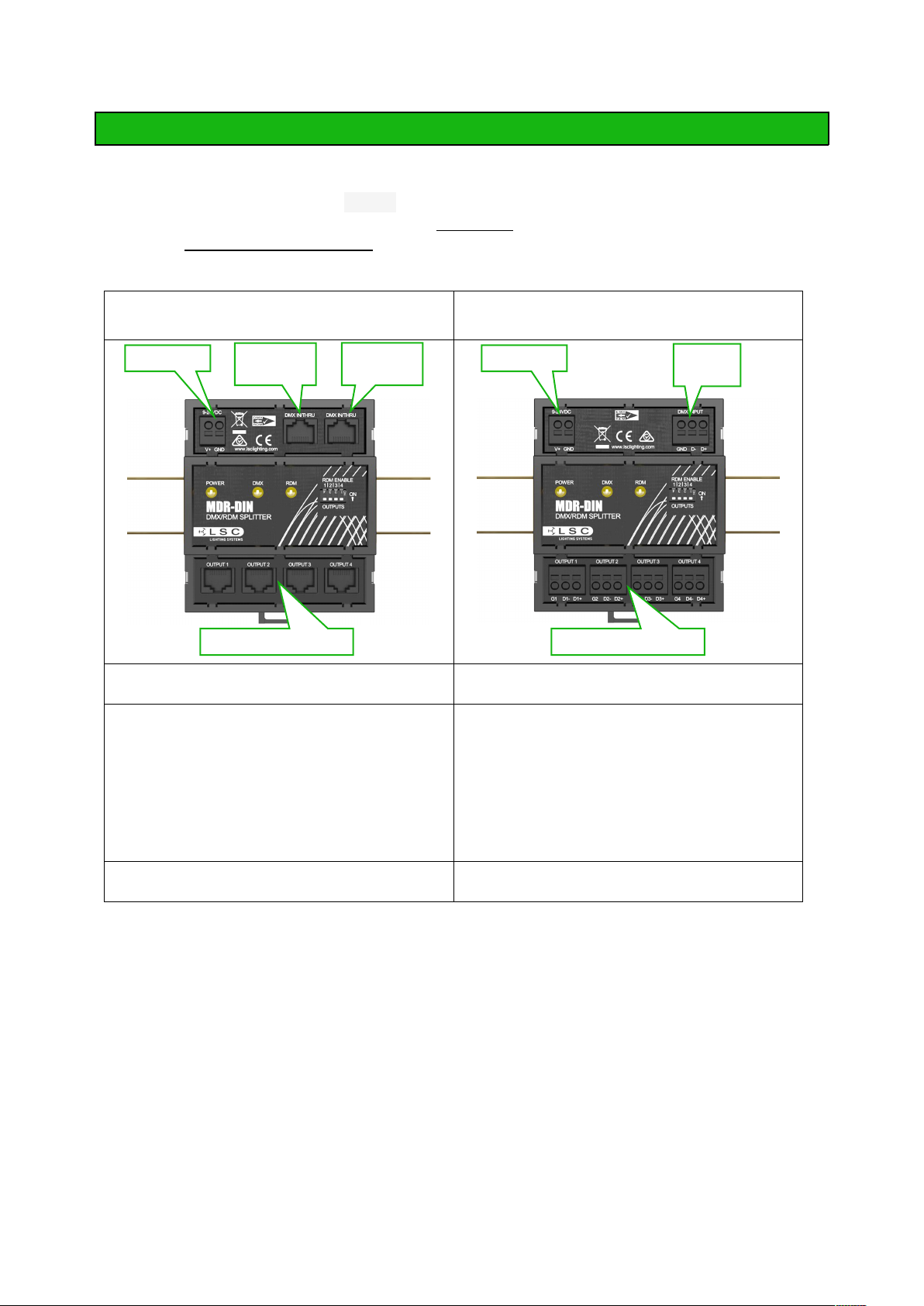
1.2 Models
Two models are available. Both models use push fit terminals for power connections.
• MDRD/T. Push-fit terminals for DMX INPUT and 4 DMX outputs
• MDRD/J. RJ45 sockets for 2 DMX IN/THRU and 4 DMX outputs for installations where
Cat-5 style cable is used for DMX512 reticulation
1.3 Features
• Four DMX/RDM outputs
• Each output is electrically isolated from the input and all other outputs
• RDM capability of each output port can be disabled for situations where legacy
equipment is not compatible with RDM signals
• Splitter is discoverable by RDM
• Outputs can be labelled via RDM
• LSC’s Houston-X monitoring and configuration system can display your network
topography
• Each output circuit can be labelled via RDM for greater clarity in more complex
networks
• LEDs for power, DMX and RDM activity
• Easy software update via RDM
• Conforms to the latest DMX/RDM standards
• CE (European) and RCM (Australian) approved
• Full two-year factory warranty
• Designed and manufactured in Australia by LSC – an Australian-owned company with
over 30 years' experience in developing world-first DMX512 products

MDR-DIN DMX Splitter
User Manual
Page 5
2 Installation
2.1 Installation
1. Mount the unit on a standard TS-35 DINrail (IEC/EN 60715). The unit is 5 modules wide.
2. Connect a suitable power source to the 9-24V DC push-fit terminals observing the correct
polarity. A minimum of 5W of power is required.
3. Connect the DMX512 cables
MDRD/J
RJ45 Connectors
MDRD/T
Push-Fit Terminals
Plug the DMX source cable into either DMX
IN/THRU connector
Connect the DMX source cable into the DMX
INPUT terminals
If this MDR-DIN splitter is the last device at
the end of the DMX512 input cable, connect
a 120 ohm resistor to the other DMX
IN/THRU connector. See section 2.4 for the
pin-outs. If the MDR splitter is not the last
device on the line, the other DMX IN/THRU
connector can be used to connect the DMX
to other equipment
If this MDR-DIN splitter is the last device at
the end of the DMX512 input cable, connect
a 120 ohm resistor across the DMX INPUT
terminals. If the MDR splitter is not the last
device on the line, the same DMX INPUT
terminals can be used to connect the DMX
to other equipment in parallel.
Connect the DMX512 output cable(s) to the
DMX512 output connector(s).
Connect the DMX512 output cable(s) to the
DMX512 output terminals.
2.2 DMX Cables
Only use specific DMX data cable. The data cable must conform to the EIA485 cable
requirements by providing the following specifications:
• Low capacitance
• One or more twisted pairs
• Foil and braid shielded
• Impedance of 85-150 ohms, nominally 120 ohms
• 22AWG gauge for continuous lengths over 300 metres
Cat 5 UTP (Unshielded Twisted Pair) and STP (Shielded Twisted Pair) cable is acceptable. If
you want to make your own cables, LSC recommends using Beldon 9842 (or equivalent). Never
use audio cable.
The end of the DMX line must be terminated (120 Ω) to prevent the signal reflecting back up the
line and causing possible errors.
Power I/P
DMX
IN/THRU
DMX
IN/THRU
Power I/P
DMX
INPUT
4 X DMX OUTPUTS
4 X DMX OUTPUTS

MDR-DIN DMX Splitter
User Manual
Page 6
2.3 Push-Fit Terminals
The following cables are suitable for use with the push-fit terminals:
• 2.5mm² stranded wire
• 4.0mm² solid wire
Stripping length is 8mm. Insert a small screwdriver into the slot adjacent to the cable hole. This
releases the spring inside the connector. Insert the cable into the round hole then remove the
screwdriver.
Solid wires or wires fitted with ferrules can often be pushed directly into the connector without
the use of the screwdriver. When connecting multiple cables to a single terminal the wires must
be twisted together to ensure a good connection to both legs. Non-insulated bootlace ferrules
can also be used for stranded cables. Ferrules are not recommended for solid cables. Insulated
bootlace ferrules can also be used allowing stranded cables to be easily inserted without the
need of a tool to actuate the spring release.
The maximum ferrule outer diameter is 4mm.
2.4 DMX Pin Outs
RJ45
Pin Number
Function
1
+ Data
2
- Data
3
Not Used
4
Not Used
5
Not Used
6
Not Used
7
Ground
8
Ground
5 pin XLR
Pin Number
Function
1
Ground
2
- Data
3
+ Data
4
Not Used
5
Not Used
3 Pin XLR
Pin Number
Function
1
Ground
2
- Data
3
+ Data
2.5 Operation
• The Power LED is lit when power is present and flashes when an RDM Identify request is
received
• The DMX LED flashes when DMX data is present
• The RDM data LED flashes when RDM data is present
2.6 RDM Enable
RDM allows RDM-based controllers and devices to communicate with each other in bidirectional
mode over the DMX cable, interleaved with the DMX512-A signal. Some older DMX-controlled
equipment is not compatible with RDM data and could flash or flicker when RDM data is present.
To overcome this problem, each individual output port can have the RDM data turned off via the
front-panel switches.
2.7 DMX Explained
DMX512-A is the industry standard for the transmission of digital control signals between lighting
equipment. It utilises just a single pair of wires on which is transmitted the level information for
the control of up to 512 DMX slots (addresses or channels). The information for each slot is sent
sequentially. The level of slot 1 is transmitted, then the level of slot 2, then 3, etc., up to a
RDM Enable
switches

MDR-DIN DMX Splitter
User Manual
Page 7
maximum of 512 slots. This stream of data containing the levels for all 512 DMX slots is repeated
a minimum (generally) of 44 times per second. This provides sufficient updates of channel
information for smooth fade transitions. DMX allows a controller to communicate with a device.
It does not allow the device to communicate with the controller.
MDRD/T
3 Compliance Statements
The MDR-DIN from LSC Control Systems Ltd is CE (European) and RCM (Australian) approved.
It has been designed and tested to the European Committee for Electrotechnical Standardization
(CENELEC) standard– EN55022 (Information Technology Equipment).
All LSC products with CE Compliance automatically comply with C-Tick requirements as per
Section 182 of the Radio communications Act 1992. LSC Company Registration number is
N921.
4 Specifications
MDRD/J
MDRD/T
Number of Buffered Outputs
4
Input and Thru Connectors
RJ45
Push-fit terminals
Output Connectors
Individual RDM Disable per Port
DMX Protocol
ANSI DMX512-A Standard E1.11:2008
(R2013)
RDM Protocol
ANSI RDM Standard E1.20:2010
Power, DMX and RDM Indicator LED
Software Upgrade via RDM
All Inputs and Outputs Isolated
Galvanic Isolation Barrier
1500V
Short Circuit Protected
DMX512-A Compatible
Power Supply Requirements (not included)
9-24V DC (5W)
Conformity
CE, RCM
Individual RDM Disable Switches (per port)
Chassis Style
TS-35 DINrail mount
(IEC/EN 60715)
Construction Style
High-strength, flame-retardant ABS
plastic material
Physical Dimensions
88mm (w) x 59mm (d) x 104mm (h)
5 DIN units wide
Actual Weight
0.16kg
Shipping Dimensions
92mm (w) x 64mm (d) x 108mm (h)
Note: All outputs are individually isolated from each other as well as the input. Isolation is for
both data and common connections and provides a galvanic barrier to 1500V. Outputs are EMI-
filtered and current-limited to protect against short circuits.
END
Table of contents
Other LSC Cables And Connectors manuals
Popular Cables And Connectors manuals by other brands

Amphenol
Amphenol PL182X-301-50-G15 Assembly manual

Bosch Thermotechnik
Bosch Thermotechnik 7 736 500 272 installation manual

Philips
Philips SWV2926W Specifications

CYP
CYP CLUX-4EN Operation manual

NEUTRIK
NEUTRIK etherCON TOP Assembly instruction

TE Connectivity
TE Connectivity DYNAMIC 5000 Series instruction sheet