MONTAJE DE CONDUCTO (Monte la caja de conexiones resistente a la intemperie usando una boquilla de conducto de 1/2”)
CABLEADO
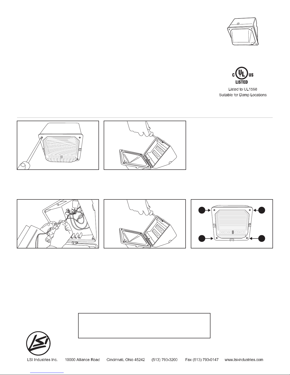
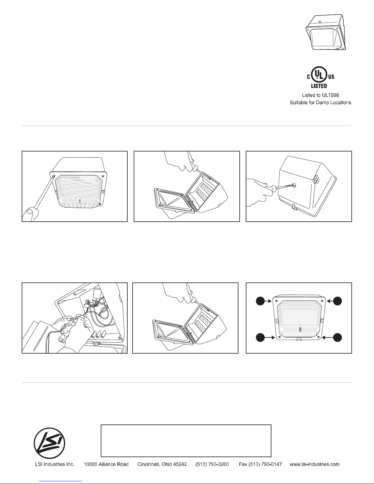
PASO 1:
Quite la carcasa delantera al sacar los
tomillos.
PASO 2:
Retire el conjunto disipador de calor de
LED (2).
PASO 3:
Saque el enchufe ciego en la parte trasera
del dispositivo. Jale los cables de suministro
a través de la placa de montaje y fíjelos a la
caja de montaje. Sujete a la caja de
montaje. Selle con sellador de silicón
resistente a la intemperie para prevenir que
la humedad entre en el dispositivo.
PASO 4:
Conecte el conector de ensamblaje. PASO 5:
Reemplace el conjunto de disipador térmico
de LED con los (2) tornillos provistos.
PASO 6:
Cierre el alojamiento frontal ajustando los
tornillos según el siguiente esquema.
1 4
3 2
Nota: El aplique LED usa un multi-voltios que detecta automáticamente, por lo que no hace falta rehacer el cableado. Revise
para estar seguro que el voltaje de suministro al dispositivo sea compatible con la reactancia del dispositivo (120-277V). Conecte el
cable blanco del dispositivo al cable blanco de servicio. Conecte el cable negro del dispositivo al cable negro de servicio. Conecte el
cable verde del dispositivo al cable de puesta a tierra. Asegúrese que todas las conexiones estén seguras usando los dispositivos
aprobados de conexión.
NOTA: Afloje dos tornillos cautivos en el lado izquierdo de la carcasa. Consulte los códigos eléctricos locales para ver los requisitos de
cableado y puesta a tierra. El dispositivo debe estar ubicado por lo menos 18” debajo de cualquier detalle estructural. El dispositivo no
debe de estar en un hueco.
IMPORTANTE: LEER ANTES DE SACAR EL ARTÍCULO DE LA CAJA. GUARDAR PARA FUTURA REFERENCIA
SEGURIDAD: Este artículo se debe conectar de acuerdo al CÓDIGO ELÉCTRICO NACIONAL y los
códigos y ordenanzas locales aplicables. Este producto lo debe instalar una persona familiarizada con la
fabricación y operación del producto y con los peligros asociados a su instalación. Un electricista autorizado
calificado debe terminar el trabajo. Por seguridad se requiere una conexión a tierra correcta.
ADVERTENCIA: Antes de instalar o realizar el mantenimiento de este artículo asegúrese que la electricidad
está APAGADA.
RIESGO DE LESIONES: El artículo puede dañarse o ser inestable si no se instala correctamente.
TMWP Series
INSTRUCCIONES DE INSTALACIÓN Y MONTAJE
Preguntas de instalación?
Llame al Departamento de Servicio de Campo de LSI en:
1-800-436-7800 Ext. 3300
Fax: 1-877-861-1368
240-135LSI Rev. 03/17 ©2017 LSI Industries Inc.