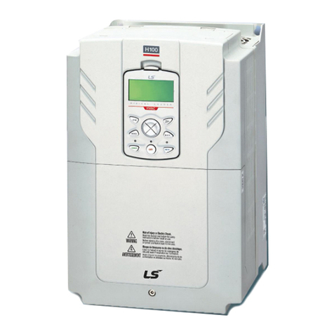
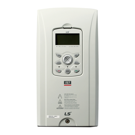
LSIS SV-iS7 series User manual


iS7 CC-Link IE Field Manual
1
Thank you for purchasing iS7 CC-Link option board of LS Variable Frequency
Drives!
Safety Instruction
To prevent injury and danger in advance for safe and correct use of the product,
be sure to follow the Safety Instructions.
The instructions are divided as ‘WARNING’ and ‘CAUTION’ which mean as follow.
WARNING
CAUTION
The meaning of each symbol in this manual and on your equipment is as follows.
This is the safety alert symbol.
This is the dangerous voltage alert symbol.
After reading the manual, keep it in the place that the user always can
Contact easily.
Before you proceed, be sure to read and become familiar with the safety
precautions at the beginning of this manual. If you have any questions, seek
expert advice before you proceed. Do not proceed if you are unsure of the safety
precautions or any procedure.
WARNING
Be cautious about dealing with CMOS elements of option board.
It can cause malfunction by static electricity.
Connection changing like communication wire change must be done with
power off.
It can cause communication faulty or malfunction.
Be sure to connect exactly between Inverter and option board.
It can cause communication faulty or malfunction.
Check parameter unit when setting parameter.
It can cause communication faulty
This symbol indicates the possibility of death or
serious injury.
This symbol indicates the possibility of injury or
damage to property.

iS7 CC-Link IE Field Manual
2
Introduction
The CC-Link IE Field Master can operate the IS7 drive and monitor the state of IS7 in
the CC-Link IE Field network through the IS7 CC-Link IE Field communication option
board.
SV-IS7 CC-Link IE Field is 1Gbps Ethernet based network. It is not compatible with
CC-Link.
1. Specification of CC-Link IE Field Communication Option Board
Item
Description
Type
Inverter plug-in option, RJ-45 Connection type
Power
From Inverter
Transmission
Speed
1 Gbps
Communication
type
Token passing
Max, number of
stations
120, Heterogeneous connections are possible.
(When used with high-capacity devices, the number of
connections decreases)
Distance
Max. 100m(Twisted pair)
Connection
Branch
No limits.
Topology
Line/Ring/Star topology
Cable
Ethernet cable (IEEE 802.3 1000BASE-T compliant cable
or ANSI/TIA/EIA-568-B(Category 5e) compliant shielded
4-pair branched cable
Connector
Shielded RJ-45
Node
Intelligent device
station
Maximum cycle
size(per node)
RX
32 bit
RY
32 bit
RWr
8 word
RWw
8 word
Transient
transmission
Not available

iS7 CC-Link IE Field Manual
3
2. Product Components
- SV-IS7 CC-Link IE Field communication option board 1 ea
- Screw for fixing on the inverter 2 ea
- SV-IS7 CC-Link IE Field User Manual 1 ea

iS7 CC-Link IE Field Manual
4
3. Installation of the SV-IS7 CC-Link IE Field Option
(1) SV-IS7 CC-Link IE Field Option Module
LINK 1
LINK 2
RUN SD
/RD
DLNK
/ERR LERR
CC-LINK IE Port
CC-LINK IE Port
Screw
Screw
(2) SV-IS7 CC-Link IE Field Option Board Layout
X1
X2
CPU
RJ45 CC-LINK IE Field
connector
RUN
SD/RD
LERR
Inverter
connector
DLNK/ERR

iS7 CC-Link IE Field Manual
5
(3) Mounting the communication option board on SV-IS7 drive
4. Network Connection
Connection terminal of communication cable
Pin No.
Signal
Description
Color
1
TX/RX+
Transmitted/Received data Plus
White/Yellow
2
TX/RX-
Transmitted/Received data Minus
Yellow
3
TX/RX+
Transmitted/Received data Plus
White/Yellow
4
TX/RX-
Transmitted/Received data Minus
Blue
5
TX/RX+
Transmitted/Received data Plus
White/Blue
6
TX/RX-
Transmitted/Received data Minus
Green
7
TX/RX+
Transmitted/Received data Plus
White/Brown
8
TX/RX-
Transmitted/Received data Minus
Brown
CC-Link IE Field
Communication
option board

iS7 CC-Link IE Field Manual
6
(4) Communication Cable Connector
** Wires connected to pin #1 and pin #2 must be twisted.
** Wires connected to pin #3 and pin #6 must be twisted.
Maximum Time-Delay for CC-Link IE Communication
The table below contains the maximum time-delays for each profile that are available
with the CC-Link IE communication option card. The time-delay is the time taken to
process data and return it to the master PLC.
When the master PLC communication cycle time is less (shorter) than the maximum
time-delay, accurate communication from the CC-Link cannot be guaranteed. To
guarantee communication accuracy, the master PLC’s communication cycle time must
be more (longer) than the maximum time-delay.
Mode
Maximum Time-delay for CC-Link
Communication
Profile1
80ms
Profile2
15ms
1
8
1
2
3
4
5
6
7
8
메모 [노태희1]: 추가_131217

iS7 CC-Link IE Field Manual
7
(1) Bandwidth
CC-Link/IE Field communication requires CAT 6a network cables.
(2) Twist- Pair Cable Types
Type
Description
Application
UTP
(U.UTP)
Unshielded high-speed
signal cable
Max. 200MHz
Voice, data and low quality video signals
FTP
(S.UTP)
Single shielded cable
(shielded core only)
*Shield material : Al/plastic complex foil
or copper braid
Max. 100MHz
Electrically stable and protected against EMI
Voice, data and low quality video signals
STP
(S.STP)
Double shielded cable
(shielded pairs and shielded
core)
*Shield material(pair): AL/Plastic
complex foil *Shield material(core):
AL/Plastic complex
Foil or copper braid
Max. 500MHz
Voice, data and video signals
Replaces 75Ωcoaxial cable

iS7 CC-Link IE Field Manual
8
(3) Network Connection
*CC-LINK IE Field Option does not distinguish the directions of LINK1 and
LINK2
Network Type
Configuration
Star topology
Line topology
Ring topology

iS7 CC-Link IE Field Manual
9
5. LED Display
4 green and red LEDs on the CC-Link IE Field communication board displays the
status of CC-Link IE Field communication board. LED is organized as following.
Green
RUN
Green/Red
SD/RD
Red
LERR
Green/Red
DLNK/ERR
LED
Name
Color
Function
RUN
Green
ON –Communication transmitting/receiving
Flickering at the 200ms –Communication
transmitting/receiving is not established
OFF –Check if the Communication cable is connected
correctly or H/W failure
SD
Green
ON –Data transmitting
OFF –Waiting for data transmission
RD
Red
ON –Data receiving
OFF –Waiting for data receive
DLNK
Green
ON –Cyclic data transmitting
OFF –Cyclic data waiting or connection termination
ERR
Red
ON –communication error with PLC/ Lost command
error
OFF –Normal state
LERR
Red
ON –Receive data error or link error
OFF –Normal state

iS7 CC-Link IE Field Manual
10
6. Trouble Shooting
LED Display
Cause
Countermeasure
RUN
SD/RD
DLINK/ERR
LERR
OFF
-
-
-
Power supply is not
energized.
Check if the communication
board is installed on the
inverter. Check if the
inverter is turned On.
Flickering
with
200ms
-
-
-
Abnormal Interface
communication
between
communication
board and inverter
Check if communication
cable and power supply
cable is separated.
After the power of inverter is
turned Off, and then
energize the power of
inverter.
-
-
RED ON
-
Communication is
not established.
Check if communication
cable and power supply
cable is separated.
After the power of inverter is
turned Off, and then
energize the power of
inverter.
-
-
-
RED
ON
Abnormal Interface
communication
between
communication
board and PLC
Check if communication
cable and power supply
cable is separated.
Check the status of the
connected nodes.

iS7 CC-Link IE Field Manual
11
7. Quick Communication Start
Install the CC-Link IE Field communication board while inverter power supply is
turned off. After inverter power supply turns on, check CNF-30 parameter. It should be
‘CC-Link IE Field’.
(1) Connect to the network with communication cable via CC-Link IE Field
communication board.
(2) Set the Network ID of inverter at parameter COM-10
(3) Set the Station ID of inverter at parameter COM-11
(4) Set to ‘Yes’at COM-94 Comm Update
(5) Check that RUN LED of CC-Link IE Field Communication board is
turned on. If not, check that the parameter value of COM-10, COM-11 of
Keypad is correct.

iS7 CC-Link IE Field Manual
12
8. Keypad Parameter related with CC-Link IE Field Communication
Code
Parameter Name
Initial Value
Range
CNF-30
Option-1 Type
-
-
DRV-06
Cmd Source
Fx/Rx-1
Keypad
Fx/Rx-1
Fx/Rx-2
Int. 485
FieldBus
PLC
DRV-07
Freq Ref Src
Keypad-1
Keypad-1
Keypad-2
V1
I1
V2
I2
Int. 485
Encoder
FieldBus
PLC
PRT-12
Lost Cmd Mode
None
None
FreeRun
Dec
Hold Input
Hold Output
Lost Preset
PRT-13
Lost Cmd Time
1.0sec
0.1~120.0sec
PRT-14
Lost Preset F
0.00Hz
0.00~400.00Hz
COM-06
FBus S/W Ver
-
-
COM-09
FBus LED
-
-

iS7 CC-Link IE Field Manual
13
(1) Option-1 Type (CNF-30)
It displays the name of communication board installed on the inverter.
It displays ‘CC-Link IE Field’when CC-Link IE Field communication board is
installed correctly and there is no fault.
(2) Cmd Source (DRV-06)
It sets the run command source of inverter
The parameter sets to ‘Fieldbus’when it commands Run/Stop operation to
inverter by CC-Link IE Field communication.
(3) Freq Ref Src (DRV-07)
It sets the frequency command source of inverter.
The parameter sets to ‘Fieldbus’when it commands Command frequency by
CC-Link IE Field communication.
COM-10
Opt Parameter1
1
1~239
Network ID
COM-11
Opt Parameter2
1
1~120
Station ID
COM-12
Opt Parameter3
0
0 (Profile1)
1 (Profile2)
COM-31
~COM-38
Para Status-1
~ Para Status-8
-
0x0000
~0xFFFF
COM-51
~COM-58
Para Control-1
~ Para Control-8
-
0x0000
~0xFFFF
COM-94
Comm Update
No
No
Yes

iS7 CC-Link IE Field Manual
14
(4) Lost Cmd Mode (PRT-12)
It designates the Run mode when Lost Command is occurred during the time
of PRT-13 Lost Cmd Time.
None: It does anything when Lost Command is occurred.
FreeRun: After the status of inverter is changed to Lost Command, motor will free-run to
stop and Trip will be occurred.
Dec: After the status of inverter is changed to Lost Command, motor will decelerate to
stop and Lost Command Stop will be occurred.
Hold Input: Running with the last Run command and Lost Command Warning will be
occurred.
Hold Output: Running with the current run speed and Lost Command Warning will be
occurred.
Lost Preset: Running with the preset value of PRT-14 and Lost Command Warning will
be occurred.
(5) Lost Preset F (PRT-14) –Lost Preset Frequency
When PRT-12 Lost Cmd Mode is set to Lost Preset, inverter will operate with
the frequency which is set in Lost Preset F at Lost Preset Frequency occurred.
(6) Lost Cmd Time (PRT-13) –Decision time of Lost Preset Frequency
If Preset Frequency is lost for the preset time of PRT-13 Lost Cmd Time, it is
recognized to Lost Preset Frequency.
If the communication is restored within the time of PRT-13 Lost Cmd Time, it
is not recognized to error.
Lost
Command
Lost
Command
PRT-13
Lost Cmd Time
PRT-13
Lost Cmd Time
Recognition of
Lost Command
The status of
Communication

iS7 CC-Link IE Field Manual
15
(7) FBus S/W Ver (COM-06)
It displays the version of communication board installed on the inverter.
(8) FBus LED (COM-09) –LED display for On/Off
It displays the status information of CC-Link IE Field communication.
It displays 4 LEDs at COM-0 FBus LED.
LED status is displayed at COM-9 FBus LED parameter by keypad. 3 LEDs
among 4 LEDs displayed indicates the status of CC-Link IE Field communication
option board. It displays the information about CPU status, Inverter Interface
disconnection and failure of saving the Station ID and Baud Rate to EEPROM in
order of from right to left.
Example of COM-09 LED status)
(9) Opt Parameter1 (COM-10) –Network ID setting
Set the network ID of CC-Link IE Field.
Physically connected communication devices must use the same
network id.
The value of Baudrate will be applied to CC-Link option board after Comm
Update sets to ‘YES’.
Bit
Description
Status
Causes of Status
0
RUN LED
ON
Normal communication
1
SD/RD LED
ON
Normal communication
2
DLNK/ERR
On or Flicker
Normal communication /
Fault has occurred.
3
LERR
On
Fault has occurred.
COM LED
RUN LED
ERR LED
CPU LED
OFF
OFF
ON
OFF

iS7 CC-Link IE Field Manual
16
(10) Opt Parameter2(COM-11) –Station Number setting
It sets the Station ID of CC-Link IE Field. It can set Station Number
from 1 to 120.
Station ID can not be duplicated. Check if Station ID is not
duplicated.
The value of Station ID will be applied to CC-Link option board after Comm
Update sets to ‘YES’.
★★★ Caution
Example of network connection)
Same station numbers can not be used more than once in a network.
Set the station number sequentially in order of connection. (Do not create a
dead station as station 1, station 2, and station 4.)
(11) Opt Parameter3 (COM-12) –Profile setting
LSIS provides two profiles.
Profile2 is more responsive than Profile1.
(12) Para Status-1~8 (COM-31~38)
It is displayed only when the setting value of COM-11 Opt
Parameter2 is ‘1’(Profile2).
It set the inverter address to read in Para Status 1~8 when read
operation of command(RWr0~7) of remote register is executed.
For example, If Para Status-1 sets to 0x0003, the saved value in
address which is set in 0x0003 will be read.
Station1
Station2
Station3
Station4
CC-Link Master
FBus ID 1
FBus ID 2
FBus ID 3
FBus ID 4
Station0

iS7 CC-Link IE Field Manual
17
(13) Para Control1~8 (COM-51~58)
It is displayed only when the setting value of COM-11 Opt
Parameter2 is ‘1’(Profile2).
It set the inverter address to read in Para Control 1~8 when read
operation of command(RWw0~7) of remote register is executed.
For example, if the value of Para Control-1 is set to 0x1004, the
value of RWw0 is written to the 0x1004 address.
(14) Comm Update (COM-94)
The value of COM-07 FBus ID and COM-10 Opt Parameter 1 will be applied
to CC-Link IE Field option board after Comm Update sets to ‘YES’.
The changed Station ID and communication speed will be applied to CC-Link
IE Field option board after Comm Update sets to ‘YES’.
9. CC-Link IE Field Data List
Inverter occupies the buffer memory 1 station of master.
It means the input/output data information between master and inverter.

iS7 CC-Link IE Field Manual
18
9.1 Details of Remote Input and Output Signals
Remote Output Signals
(Master unit to Inverter)
Remote Input Signals
(Inverter to Master unit)
Device No.
Signal Function
Device No.
Signal Function
RY0
Forward running
command
RX0
Forward running
RY1
Reverse running
command
RX1
Reverse running
RY2~8
N/A
RX2
Accelerating
RX3
Decelerating
RX4
Reach to preset speed
RX5
DC Braking
RX6
N/A
RX7
Relay1 output terminal
RX8
Relay2 output terminal
RY9
Output stop
RX9
Q1 output terminal
RYA~B
N/A
RXA
N/A
RXB
N/A
RYC
Monitor command
RXC
Monitoring
RYD
Frequency setting
command 1
(RAM)
RXD
Frequency setting
completion 1
(RAM)
RYE
Frequency setting
command 2
(EEPROM)
RXE
Frequency setting
completion 2
RYF
Instruction code
execution request
RXF
Instruction code execution
completion (EEPROM)
RY10~19
N/A
RX10~19
N/A
RY1A
Error reset request flag
RX1A
Error status flag
RY1B
N/A
RX1B
Available status to run
RY1C~1F
System reservation
RX1C~1F
System reservation

iS7 CC-Link IE Field Manual
19
9.2 Remote output
Remote Output Signals (Master to Inverter)
Device
No.
Signal Function
Description
RY0
Forward running
command
ON
Forward running start
OFF
Stop command
RY1
Reverse running
command
ON
Reverse running start
OFF
Stop command
RY2~8
N/A
-
RY9
Interrupting of
inverter output
When it turns On, motor free-run to stop.
RYA~B
N/A
-
RYC
Monitor command
When monitor command (RYC) is switched On, the
corresponding monitor value to RWw0 is saved in
RWr0. RXC (Monitoring) switches On.
Only works when the Profile 1 is selected.
RYD
Frequency setting
command 1
(RAM)
When frequency setting command 1 (RYD) is
switched On, command frequency (RWw1) is
written to RAM of the inverter. Frequency setting
completion 1 (RXD) is turned On after completion of
write.
Only works when the Profile 1 is selected.
RYE
Frequency setting
command 2
(RAM, EEPROM)
When the frequency setting command (RYE) is
switched on, the set frequency (RWw1) is written to
RAM and EEPROM of the inverter. On completion
of write, frequency setting completion (RXD)
switches on. The set frequency is remained even if
power of inverter is switched On/Off.
Only works when the Profile 1 is selected.
RYF
Request for
command code
execution
It requests the execution of the command code
(RWw2). In case command code is Write request,
the value of RWw3 is valid.
Only works when the Profile 1 is selected.
RY10~19
N/A
-
Other manuals for SV-iS7 series
8
Table of contents
Other LSIS DC Drive manuals

LSIS
LSIS S100 Series User manual

LSIS
LSIS SV-iS7 series User manual

LSIS
LSIS LSLV-H100 User manual

LSIS
LSIS Starvert iG5A Series User manual

LSIS
LSIS SV008iC5-1F User manual

LSIS
LSIS S100 Series User manual

LSIS
LSIS iS7 Series Use and care manual

LSIS
LSIS 004iC5-1 User manual

LSIS
LSIS S100 Series User manual

LSIS
LSIS H100 User manual