ITOH DENKI POWER MOLLER 24 CBM-103FN User manual

2 Great Valley Blvd., Wilkes-Barre, PA 18706
Office Ph: 570-820-8811
Fax: 570-820-8838
www.itohdenki.com
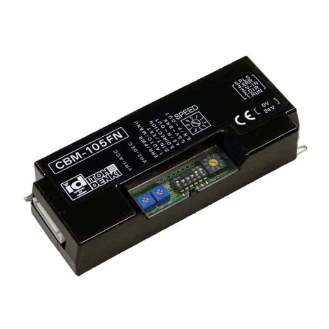
CBM-103FN/FP
Specifically designed for the KE series Power Moller® family
Adjustable acceleration and deceleration time (0 to 2.5s)
Stable speed operation
Manual or automatic recovery from thermal overload and low voltage
One (1) rotary switch to select up to 10 different fixed speeds
Two (2) LEDs (green & red) to identify error type
Pulse signal output to indicate motor revolution (2 pulses/motor revolution)
RoHS and EMC conformity
Low Voltage Protection
External Direction control
Specifications subject to change without notice
Features:
Driver Card Manual

2 Great Valley Blvd., Wilkes-Barre, PA 18706
Office Ph: 570-820-8811
Fax: 570-820-8838
www.itohdenki.com
CN1
2 PIN Connector
POWER
Connector on Card
WAGO #231-432/001-000
Connector for Wiring
WAGO ##231-102/026-000
Pin
Description
1
+24V DC
Wire size
28~14 AWG
2
0V
CN3
7 PIN Connector
MOTOR
Connector on Card
JST #S7B-XH-A
Connector for Wiring
JST #XHP-7
Pin
Description
1
GND – Grey
Wire size:
28~22 AWG
Terminal Pins:
JST #SXH-001T-P0.6
2
+12V DC – Blue
3
Hall sensor U - Violet
4
Hall sensor V – Orange
5
Hall sensor W – Green
6
Thermistor – Light Blue
7
Not Used
CN4
PIN Connector
MOTOR
Connector on Card
JST #S3P-VH
Connector for Wiring
JST #VHR-3N
Pin
Description
1
Motor phase U – Red
Wire size:
20~16 AWG
Terminal pins:
JST SVH-41T-P1.1
2
Motor phase V – White
3
Motor phase W – Black
Specifications
Specifications subject to change without notice
Connections:
KE Motor Cable:

2 Great Valley Blvd., Wilkes-Barre, PA 18706
Office Ph: 570-820-8811
Fax: 570-820-8838
www.itohdenki.com
CN2
5 PIN Connector
CONTROL
Connector on Card
WAGO #733-365
Connector for Wiring
WAGO #733-105
Pin
Description
1
+24V DC (PNP) or 0V (NPN) input – RUN
Wire Size:
28~20 AWG
2
+24V DC (PNP) or 0V (NPN) input – DIR
3
0 ~ +10V DC input – V-IN (speed variation)
4
+24V DC or 0V output – ERR
5
0V (NPN) output – PLS (pulse)
Specifications
Specifications subject to change without notice
Control connections:
Press down spring clamp in connector with a
small screwdriver.
Insert leads in proper order.
Lead should be stripped approx: 0.31~0.35”
WAGO connector (included) must be inserted
and/or pulled out carefully, so as not to
damage other parts

2 Great Valley Blvd., Wilkes-Barre, PA 18706
Office Ph: 570-820-8811
Fax: 570-820-8838
www.itohdenki.com
Specifications
Specifications subject to change without notice
Electrical: 24V DC ±10% input
- Battery
- Power Supply: fullwave rectified, smooth current <10% Ripple
Power ON delay < 1s
10A locking current
Input signals (minimum 2.2mA, maximum 7.3mA)
- NPN (0V)
- PNP (+24V DC)
Output signals (open collector 24V, 25mA or less)
- NPN (0V)
- PNP (+24V DC; selectable for Error only)
Applicable Models: PM635KE
Brake: Dynamic (electric)
Protection: Motor control thermal protection
- 95°C (203°F) on the PCB
- 105°C (221°F) in the motor
Built-in diode for incorrect wiring protection
Built-in 18A in-line fuse for supply protection
Built-in thermal fuse to prevent overheating
- 139°C (282°F)
environment: Temperature 0~40° C (32~104° F)
<90% Relative Humidity (No condensation)
No corrosive gas
Vibration <0.5G

2 Great Valley Blvd., Wilkes-Barre, PA 18706
Office Ph: 570-820-8811
Fax: 570-820-8838
www.itohdenki.com
Switch
Function
Position
Initial Setting
Up
Down
SW3
Error Output
NPN
PNP
NPN: CBM-103FN
PNP: CBM-103FP
Switch
Function
Position
Initial Setting
Left
Right
SW5
Input Type
NPN
PNP
NPN: CBM-103FN
PNP: CBM-103FP
Operation
Specifications subject to change without notice
DIP Switches – User Settings:
switches:
DIP-
SW
Function
ON Setting
OFF Setting
Initial
Setting
1
Error recovery:
Thermal;
Low voltage;
Induced voltage
Manual Reset
Automatic Reset
ON
See Page 8
2
Speed change
selection
External Voltage
Input
Internal Rotary
Switch
OFF
See Page 6
3
Motor Direction
(no external DIR
signal; viewed
from cable side)
CW
CCW
OFF
4
ERR output
Normal, ON
Error, OFF
OFF
Potentiometers:
VR1 – Acceleration: Adjust acceleration time
from 0~2.5s after the RUN signal is applied
VR2 – Deceleration: Adjust deceleration time
from 0~2.5s after the RUN signal is removed
* VRs turn 270°

2 Great Valley Blvd., Wilkes-Barre, PA 18706
Office Ph: 570-820-8811
Fax: 570-820-8838
www.itohdenki.com
Specifications subject to change without notice
operation
LED AND ERROR INDICATIONS:
LED 1: Green (power)
LED 2: Red (error condition)
Motor pulse output signal
0V (NPN) output from CN2-5
Two (2) pulses per motor revolution
Maximum speed pulse frequency approximately 147Hz

2 Great Valley Blvd., Wilkes-Barre, PA 18706
Office Ph: 570-820-8811
Fax: 570-820-8838
www.itohdenki.com
Specifications subject to change without notice
operation
error list:
Automatic Recovery:
DIP switch 1 – OFF
Toggling the run signal (OFF/ON) is not necessary
Thermal error resets 60s AFTER operating temperature is restored
Low voltage error resets as soon as the supply voltage rises above 18V
Induced voltage error resets 1s AFTER induced voltage drops and stays below 30V
Error
Description
Solution
Fuse or temperature
fuse, blown
> 18A through circuit or
> 139°C (282°F)
Replace Card
Motor disconnected
(CN3 or CN4)
Motor connector(s)
unplugged
Plug in appropriate connectors
Stalled motor
RUN signal turns ON,
but motor does not
turn for 1s
After motor shuts off
Turn OFF RUN signal,
then turn back ON
Thermal error
(PCB or motor)
Motor control circuit
has reached 95°C
(203°F) on the PCB or
105°C (221°F) in the
motor
After operating
temperature is
restored
Low voltage
Supply voltage has
dropped < 15V for at
least 1s or dropped <
15V five times within
0.5s
After supply voltage
rises > 18V
Induced voltage
(overspeeding)
Voltage from motor
rises > 40V
After induced voltage
drops < 30V

2 Great Valley Blvd., Wilkes-Barre, PA 18706
Office Ph: 570-820-8811
Fax: 570-820-8838
www.itohdenki.com
Rotary
Switch
V-IN (V)
Speed (ft/min) +/- 5%
1-stage
2-stage
3-stage
9
9.69 ± 0.25
758.0
199.5
52.5
8
9.06 ± 0.25
710.6
187.0
49.2
7
8.44 ± 0.25
663.3
174.5
45.9
n/a
7.81 ± 0.25
615.9
162.1
42.7
6
7.19 ± 0.25
568.5
149.6
39.4
n/a
6.56 ± 0.25
521.1
137.1
36.1
5
5.94 ± 0.25
473.8
124.7
32.8
n/a
5.31 ± 0.25
426.4
112.2
29.5
4
4.69 ± 0.25
379.0
99.7
26.2
n/a
4.06 ± 0.25
331.6
87.3
23.0
3
3.44 ± 0.25
284.3
74.8
19.7
n/a
2.81 ± 0.25
236.9
62.3
16.4
2
2.19 ± 0.25
189.5
49.9
13.1
1
1.56 ± 0.25
142.1
37.4
9.8
0
0.94 ± 0.25
94.8
24.9
6.6
n/a
0.31 ± 0.25
47.4
12.5
3.3
Specifications subject to change without notice
Operation
speed change table:
10 speed steps
available through on-
board rotary switch
16 speed steps
available through
external voltage input
(V-IN)

2 Great Valley Blvd., Wilkes-Barre, PA 18706
Office Ph: 570-820-8811
Fax: 570-820-8838
www.itohdenki.com
Specifications subject to change without notice
Operation
1. Pry open the plastic cover at
screwdriver slots on back of card
2. Change internal dip switch(es)
to appropriate setting and
replace cover
npn or pnp inputs/outputs:
The card(s) are ordered with the inputs/outputs preset from the factory – ALL NPN or ALL
PNP.
The model designation will show the factory preset.
CBM-103FN – NPN input/output type
CBM-103FP – PNP input/output type
If it is necessary to change the input or output type, the internal dip switch(es) will need
to be changed as shown below:
Position for Input
Signal Type (SW5)
Initial Setting
NPN Setting
PNP Setting
Right
Left
Right: CBM-103FN
Left: CBM-103FP
Position for Output
Signal Type (SW3)
Initial Setting
NPN Setting
PNP Setting
Up
Down
Up: CBM-103FN
Down: CBM-103FP

Precaution
Action
Reason
Power supply
If the power supply is not sized
appropriately for the number of
cards/rollers it provides power to,
then a low voltage condition may
occur.
If the voltage drops below 15V DC and remains low
for 1s, then the low voltage error will appear.
If the voltage drops below 15V DC five times in 0.5s,
then the low voltage error will appear.
If the voltage drops below 15V DC less than five
times in 0.5s or does not remain low for 1s, the
roller may stutter – quickly turning off then on.
Multiple power
supplies
0V line of all power supplies on the
same conveyor line (powering the
card/rollers, & controls) need to be
physically linked together
This completes the signal path from one section of the
conveyor (powered by a power supply) to the adjacent
section of conveyor (powered by another power
supply) and allows for proper communication through
the cable and external interfaces.
Voltage drop
across the
power bus
Use suitable gauge wire in relation to
distance and current draw to prevent
voltage drop.
Operating DC voltage is 24V ±10%
When running long distances from a DC power supply,
the voltage drop during motor operation across the
power bus may be significant (may drop below 15V). If
there is a large enough drop in voltage, the roller(s)
may behave in a strange manner. In order to prevent
this, a larger gauge wire must be used.
Grounding
Ensure the control card is securely
grounded to the conveyor frame. The
conveyor frame should also be at the
same potential reference as earth
ground. Standard grounding practices
should be followed.
Static discharge may interfere and damage internal
components.
Electrical
24V DC ±10%
4A maximum current limiter (motor
lock is 4A)
Diode protection for miswiring
Sensor power short circuit protection
5A fuse for power supply protection
Improper power will damage the card. The motor/ card
should not be subject to locked conditions repeatedly.
Internal fuse is not replaceable. If the fuse has blown,
more serious damage has occurred within the
card/motor
Environment
Ambient temperature is 32~104°F
Ambient humidity is < 90% RH
Atmosphere has no corrosive gas
Vibration is < 0.5G - Indoor use only
Extreme environmental variables may cause poor or no
performance and damage the card.
Over-Speeding
Over-speeding of the roller’s no-load
speed by more than 50% may cause
damage.
Back EMF will be generated.
2 Great Valley Blvd., Wilkes-Barre, PA 18706
Office Ph: 570-820-8811
Fax: 570-820-8838
www.itohdenki.com
Specifications subject to change without notice
Installation Precautions IMPORTANT: PLEASE READ
BEFORE ISNTALLATION

2 Great Valley Blvd., Wilkes-Barre, PA 18706
Office Ph: 570-820-8811
Fax: 570-820-8838
www.itohdenki.com
Revision
Number
Change
Changed by:
11-0914
Initial Document
12-1226
Added autosensing inputs and precautions for electrical potential
13-0314
Added diode recommendation and wiring diagram
13-0514
Removed auto-sensing feature
14-1219
Added internal input type switch
15-0409
Added internal output type switch and mirrored induced and low
voltage errors
JC and BB
19-0108
Updated company address
REVISION HISTORY
This manual suits for next models
1
Table of contents
Other ITOH DENKI DC Drive manuals

ITOH DENKI
ITOH DENKI CB-016BP7 User manual

ITOH DENKI
ITOH DENKI CB-016 series User manual

ITOH DENKI
ITOH DENKI POWER MOLLER 24 HBM-604BN User manual

ITOH DENKI
ITOH DENKI POWER MOLLER 24 HBK-608FN User manual

ITOH DENKI
ITOH DENKI POWER MOLLER HBV-609 Guide

ITOH DENKI
ITOH DENKI Power Moller 24 CBM-105FN User manual

ITOH DENKI
ITOH DENKI CBM-105 FN User manual

ITOH DENKI
ITOH DENKI POWER MOLLER 24 HB-510N User manual

ITOH DENKI
ITOH DENKI CB-016BP7 User manual

ITOH DENKI
ITOH DENKI POWER MOLLER HBM-604BN User manual