LT LTE-1-01 Series User manual

Print status 08/2023, English
Operating instructions
Extender
Type: Liquidtool Extender
Product number: LTE-1-01-XXXXXX
Year of manufacture: 2023
Follow these instructions for proper and safe use.
Keep for future reference.


Extender
Table of contents
Print status 08/2023, English
3
TABLE OF CONTENTS
Table of contents ......................................................................................................... 3
Purpose of the operating instructions....................................................................... 5
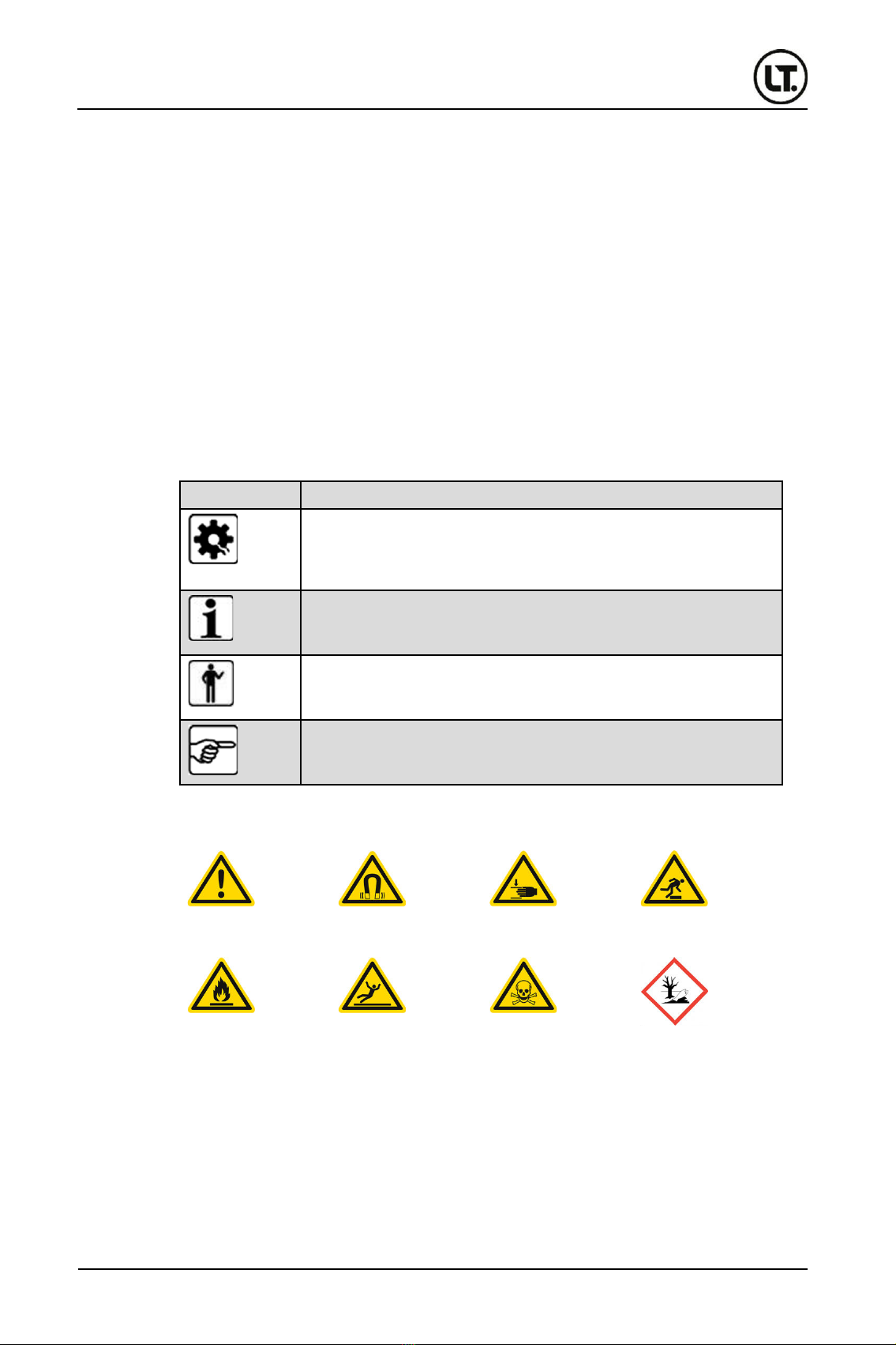
Orientation in the operating instructions .................................................................. 5
1Identification ................................................................................................. 7
1.1 Product labeling .................................................................................................... 7
1.2 Manufacturer's data............................................................................................... 7
1.3 Nameplate............................................................................................................. 8
1.4 Declaration of conformity....................................................................................... 9
2Basic safety instructions ........................................................................... 10
2.1 Operator's duty of care........................................................................................ 10
2.2 General occupational safety................................................................................ 10
2.2.1 Personnel qualification............................................................................. 10
2.2.2 Authorized personnel ............................................................................... 11
2.3 Residual hazards ................................................................................................ 11
2.3.1 Hazards due to electrical energy.............................................................. 11
2.3.2 Hazards due to magnetism ...................................................................... 11
2.3.3 Hazards due to leakage and hose lines ................................................... 12
2.3.4 Hazards due to cooling lubricant (KSS) ................................................... 13
2.4 Safety instructions of the extender ...................................................................... 14
2.5 Emergency information ....................................................................................... 14
3Description, structure and function.......................................................... 15
3.1 Intended use ....................................................................................................... 15
3.2 Reasonably foreseeable misapplication.............................................................. 15
3.3 Conversions and modifications ........................................................................... 15
3.4 Technical data..................................................................................................... 15
3.5 Location requirements......................................................................................... 16
3.6 Structure.............................................................................................................. 16
3.7 Function and system description......................................................................... 17
3.8 LED status light ................................................................................................... 17
3.9 Interfaces ............................................................................................................ 18
4Transport, installation and storage .......................................................... 19
4.1 Introductory notes on safety ................................................................................ 19
4.2 Packing ............................................................................................................... 19
4.3 Transport............................................................................................................. 19
4.4 Delivery ............................................................................................................... 20
4.4.1 Scope of delivery ..................................................................................... 20
4.4.2 Inspection for transport damage .............................................................. 20
4.5 Download app ..................................................................................................... 21
4.6 Storage................................................................................................................ 21
5Commissioning........................................................................................... 22
5.1 Introductory notes on safety ................................................................................ 22
5.2 Installation ........................................................................................................... 22
5.3 Notes on connecting the extender....................................................................... 23
5.4 Connection .......................................................................................................... 24
6Operation..................................................................................................... 31
6.1 Introductory notes on safety ................................................................................ 31

Extender
Table of contents
4
Print status 08/2023, English
6.2 Switch on extender.............................................................................................. 31
6.3 Switch off extender.............................................................................................. 31
6.4 Operation ............................................................................................................ 31
7Decommissioning....................................................................................... 32
7.1 Introductory notes on safety ................................................................................ 32
7.2 Dismantling ......................................................................................................... 32
7.3 Cleaning.............................................................................................................. 35
8Maintenance and repair.............................................................................. 35
8.1 Troubleshooting .................................................................................................. 35
9Waste disposal............................................................................................ 36
9.1 Introductory notes on safety ................................................................................ 36
9.2 Dismantling ......................................................................................................... 36
9.3 Proper and environmentally compatible disposal ................................................ 36
9.4 Disposal points.................................................................................................... 36

Extender
Purpose of the operating instructions
Print status 08/2023, English
5
PURPOSE OF THE OPERATING INSTRUCTIONS
Before operating the Extender for the first time or when you are assigned to do other work on
the Extender, you must read the Operating Instructions.
The use and handling of the extender described below is not self-evident and is explained in
detail in the accompanying technical documentation.
Pay particular attention to chapter "2 Basic safety instructions".
The operating instructions will help you to use the Extender properly, effectively and safely in
accordance with its intended purpose. Therefore, read the following chapters carefully and
attentively. If necessary, always refer to the information that is important to you.
The operating instructions inform and warn you of residual risks against which risk reduction by
design and protective measures is not or not completely effective.
ORIENTATION IN THE OPERATING INSTRUCTIONS
These operating instructions contain the following general information symbols to guide you, the
reader, through the operating instructions and to provide you with important information.
Pictogram
Meaning
Caution possible property damage
This pictogram indicates that material damage to the extender may occur
during an action if the action specifications are not correctly observed and
performed.
Important information
This pictogram indicates important additional information that includes a
warning of a hazard.
Personnel qualification
This pictogram indicates which personnel (target group) are allowed to
perform the actions in the respective chapter.
Instruction for action
This pictogram indicates an instruction for action and always precedes an
active action to be performed by the user.
Tab. 1: General pictograms and their meaning
Warning symbols warn of danger spots, risks and obstacles.
Danger point
warning
Magnetic field
warning
Warning of crushing
hazard
Warning of trip
hazards
Warning of
flammable
substances
Slip hazard warning
Warning against
substances harmful
to health
Environmental
damage warning
Operating
instructions
Residual risks
Representation of
general
information
symbols
Possible symbols
in an instruction
manual

Extender
Orientation in the operating instructions
6
Print status 08/2023, English
Commandment symbols are used for accident prevention at the workplace
General bid symbol
Wear safety shoes
Wear protective gloves
Wear appropriate work
clothes
Wear safety goggles
Read instruction
Prohibition symbols contribute to more safety.
General prohibition symbol
Prohibition for persons with pacemaker
Prohibition of food and beverages in the
workplace prohibited
Prohibition of open fire and ignition sources

Extender
Identification
Print status 08/2023, English
7
1IDENTIFICATION
1.1 Product labeling
Extender
Product number: LTE-1-01-XXXXXX
Year of manufacture: 2023
1.2 Manufacturer information
Headquarters
Liquidtool Systems AG
Winterseistrasse 22
3415 Hasle-Rüegsau
Switzerland
Email:
Internet:
www.liquidtool.com
Tab. 2: Manufacturer's data

Extender
Identification
8
Print status 08/2023, English
1.3 Nameplate
The extender is clearly identified by the nameplate and the product information on the product.
The nameplate of the extender is located on the bottom of the extender.
Fig. 1: Mounting location
1
Nameplate
Fig. 2: Nameplate
1
Company address
2
For EU member states only: Disposal notice for electrical appliances
3
Year of manufacture indication

Extender
Identification
Print status 08/2023, English
9
1.4 Declaration of Conformity
Fig. 3: Declaration of conformity

Extender
Basic safety instructions
10
Print status 08/2023, English
2BASIC SAFETY INSTRUCTIONS
2.1 Duty of care of the operator
The following requirements are placed on the technical condition of the extender and must be
ensured by the operator:
•The extender may only be used as intended
•The extender must always be checked for their proper technical condition before being
switched on
•The safety devices must be checked regularly for proper functioning
•The safety and warning notices attached to the extender must not be removed and must be
regularly checked for legibility and replaced if necessary
•No unauthorized conversions, manipulations and modifications may be made to the
extender
•The operating instructions must always be available in legible condition and complete at the
place of use of the Extender, this also applies to the instructions from suppliers.
2.2 General occupational safety
2.2.1 Personnel qualification
Important information about personnel qualification
All activities on the Extender may only be carried out by instructed, trained and
authorized persons.
WARNING
Danger due to insufficient personnel qualifications
There is a risk of serious injury and considerable damage to property if
unqualified personnel are in the danger zone or carry out work on the
Extender.
➢Operating personnel must meet the specified qualification.
➢Unqualified personnel must be kept away from the hazardous area.
A trained/instructed person is a person who has been instructed and, if necessary, trained about
the tasks assigned to him/her and the possible dangers in case of improper behavior. He/she
has also been instructed about the necessary protective equipment and protective measures.
Personnel to be trained, instructed or undergoing general training may only work under the
constant supervision of an experienced person. The personnel has read and understood the
operating instructions.
Technical
condition of the
extender
Trained, instructed
operating
personnel

Extender
Basic safety instructions
Print status 08/2023, English
11
A specialist is defined as a person who has successfully completed vocational training. The
specialist must also have knowledge of the relevant standards and regulations. They must be
able to assess the work assigned to them and, on the basis of their professional training and
work experience, must be able to recognize and avoid potential hazards on their own.
The electrician is a person in the sense of a specialist with special knowledge in the field of
electrical engineering (training in a recognized training profession as a journeyman/skilled
worker, master craftsman, industrial foreman, state-certified technician, graduate engineer,
bachelor or master).
2.2.2 Authorized personnel
Life phase/chapter
Personnel qualification
Transport, installation and
storage
•Trained, instructed operating personnel
Commissioning
•Trained, instructed operating personnel
•Specialist
•Qualified electrician for work on electrical systems or
equipment
Operation
•Trained, instructed operating personnel
Decommissioning
•Trained, instructed operating personnel
•Specialist
•Qualified electrician for work on electrical systems or
equipment
Service and maintenance
•Trained, instructed operating personnel
•Specialist
•Qualified electrician for work on electrical systems or
equipment
Disposal
•Trained, instructed operating personnel
•Specialist
•Qualified electrician for work on electrical systems or
equipment
Troubleshooting
•Specialist
•Qualified electrician for work on electrical systems or
equipment
Tab. 3: Authorized personnel
The personnel working on the extender must be regularly trained and instructed by the operator.
2.3 Residual hazards
2.3.1 Hazards due to electrical energy
The extender is connected to the power supply via a 24 volt power supply unit. When
connecting the power supply to the extender, check that the cable is seated correctly.
Before maintenance work or disassembly, disconnect the power plug and thus disconnect the
extender from the power supply.
The electrical equipment of the Extender must be checked at regular intervals. Defects, such as
loose connections, rubbed or scorched cables, must be rectified immediately by a qualified
electrician.
The Extender must be switched off immediately in the event of faults in the electrical power
supply.
2.3.2 Magnetism hazards
The extender is attached to surfaces by powerful magnets. These magnets cause
electromagnetic fields that can affect pacemakers and similar devices. This can lead to
malfunctions in pacemakers. The electromagnetic field affects devices in the immediate vicinity,
Specialist
Electrician
Instruction
Hazards due to
strong magnets

Extender
Basic safety instructions
12
Print status 08/2023, English
the perimeter is about 0.5 meters around the extender. Persons with pacemakers should not
stay in this field.
WARNING
Danger from strong magnets
The magnets cause strong, electromagnetic fields that can affect and
interfere with electronic devices such as pacemakers. Malfunctioning
pacemakers can cause death or serious injury to affected individuals.
➢Persons with pacemakers must not be in the vicinity of the extender.
➢Persons with pacemakers must not perform any activities with the
extender.
➢Regularly check this warning notice on the extender or on the machine
tool. Replace damaged warning notices immediately.
The hazard exists even when the extender is switched off, the magnets are always active.
Persons with pacemakers must therefore not carry out any activities with the extender (neither
transport, commissioning, disposal or maintenance and servicing).
In addition, regularly check the warning signs attached to the machine tool for damage. Only
these pictograms can warn and protect uninvolved third parties from the magnets. For this
purpose, comply with the information in the maintenance plan.
The extender is attached to surfaces such as machine housings by strong magnets. During
assembly, the magnetic effect can instantly pull the extender to the surface. If the fitter does not
pay attention to his fingers, they can be crushed. This can result in slight bruising of individual
fingers or fingertips. The extender has recessed grips on the housing to protect against
crushing. Together with appropriate care, the extender can be mounted without risk.
The extender is attached to surfaces by means of magnets. If the magnetic adhesion of the
surface is too low or non-existent, the extender may fall down. Falling down can crush the
installer's feet. If the extender falls to the floor, it can be damaged.
Test the magnetic effect of the surface by carefully moving the extender towards it. Observe the
magnetic effect and hold the extender by the recessed grips to prevent your fingers from being
crushed. Then observe the extender for a short time to see if it moves and threatens to fall off. If
the extender moves, a different surface must be selected for attachment.
2.3.3 Hazards due to leakage and hose lines
The extender is connected to a cooling lubricant tank via hose lines. If these lines are not laid
properly or if damaged lines are used, this will lead to leaks and cooling lubricant will escape.
Escaping cooling lubricant can cause injuries (e.g. by slipping). Therefore, lay the hose lines
carefully and without tripping. Before commissioning, check the assembly of the hose lines on
the cooling lubricant container and extender. Comply with the specifications in the maintenance
plan for regular checks.
The extender is connected to the tank of the cooling lubricant with hose lines. These hose lines
must be laid carefully to prevent the risk of tripping. Persons who trip over hose lines can fall
and injure themselves. In addition, the lines or the connections on the extender or on the tank
can be damaged and cooling lubricant can escape in an uncontrolled manner.
Risk of crushing
due to magnets
Falling extender
Leakage and
defective hose
lines
Risk of tripping
due to cables

Extender
Basic safety instructions
Print status 08/2023, English
13
2.3.4 Hazards due to cooling lubricant (KSS)
Depending on the cooling lubricant used, there may be various hazards and risks. Therefore, be
sure to read the data sheet of the cooling lubricant!
WARNING
Damage to health due to cooling lubricant
Direct contact of cooling lubricant with the skin can lead to illness and
damage to health.
Direct eye contact with cooling lubricant can cause severe irritation of the
eyes.
Inhalation of the vapors or aerosols may cause irritation and respiratory
diseases.
Escaping and/or splashing cooling lubricant can contaminate food or drink.
➢Observe the data sheet of the cooling lubricant.
➢Wear protective gloves.
➢Wear protective goggles.
➢During maintenance, servicing, cleaning and disposal, note that
residues of the cooling lubricant are present in the lines and in the unit
even after it has been switched off.
➢Eating and drinking in the vicinity of cooling lubricant is prohibited!
➢Contact a doctor immediately if you experience any discomfort.
Spilled cooling lubricant must be wiped up and disposed of immediately. There is a danger of
slipping! Persons could slip in it and injure themselves. Therefore, also check the lines regularly
for leaks (see maintenance schedule).
NOTE
Environmental damage due to leaking cooling lubricant
Escaping cooling lubricant damages the environment and can be the trigger
for further hazards.
➢Observe the data sheet of the cooling lubricant.
➢Regularly check pipelines for leaks.
➢Remedy any leaks discovered immediately.
➢Dispose of cooling lubricants in accordance with regulations.
➢During maintenance, servicing, cleaning and disposal, note that
residues of the cooling lubricant are present in the lines and in the unit
even after it has been switched off.
➢Notify the appropriate environmental agency in the event of large spills.
Hazard due to
cooling lubricants
(KSS)

Extender
Basic safety instructions
14
Print status 08/2023, English
2.4 Safety instructions of the extender
The extender is supplied with several pictograms and warnings as stickers. Due to the small
size of the product, these cannot be attached to the extender. During assembly, they must
instead be affixed in the vicinity of the extender, e.g. on the housing of the machine tool. These
stickers must be checked regularly. Damaged stickers must be replaced immediately.
Fig. 4: Safety instructions on the machine tool (example)
1
2
3
2.5 Emergency information
In the event of an emergency on the Extender, it must be put out of operation by disconnecting
the power plug. It must be checked whether there are any injured persons.
SAFETY NOTE
In case of malfunction or emergency, immediately pull out the mains
plug!
This disconnects the extender from the power supply and thus shuts it down
immediately.
Important information for your safety
You are responsible!
In any case, the safety instructions in chapter "2 Basic safety instructions" and the
locally applicable safety regulations must be observed and complied with.
Important information in the data sheet of the cooling lubricant
There are different cooling lubricants which can have different effects on health.
In case of emergencies, observe the data sheet of the cooling lubricant!
Behavior in an
emergency

Extender
Description, structure and function
Print status 08/2023, English
15
3DESCRIPTION, STRUCTURE AND FUNCTION
3.1 Intended use
The extender may only be used in combination with the Liquidtool sensor. It is used to extend
the functionality of the sensor and thus, together with the SmalrFiller, enables the automatic
filling of a machine tool with cooling lubricant. The cooling lubricant must be water emulsifiable.
For the measurement, the extender requires access to the cooling lubricant tank of a machine
tool. The access is established via the hose lines. The app belonging to the extender then
collects the determined data.
The extender may only be used if:
•This is in technically perfect condition
•The personnel has the necessary safety and hazard awareness
•The instructions in the operating manual are followed
3.2 Reasonably foreseeable misapplication
The Extender is not intended for any purpose other than the intended use listed here.
In principle, any use other than the intended use is considered improper use. This means that
safe operation is no longer guaranteed. The operator, and not the manufacturer, is responsible
for all personal injury and damage to property resulting from improper use.
Foreseeable misapplication also includes:
•Improper mounting, commissioning, operation and maintenance of the Extender
•Operating the extender in a faulty state
•Operating the extender without protective coverings
•Setting up or operating the Extender in potentially explosive atmospheres
•Use of operating materials that are not approved by the manufacturer
3.3 Conversions and modifications
For safety reasons, conversions and modifications to the extender are only permitted after
consultation with the manufacturer.
The use of non-original spare parts may invalidate liability for any resulting consequences.
Therefore, always use only the specified spare parts, this applies in particular to safety-relevant
components.
3.4 Technical data
Value
Unit
Length/Depth
525
mm
Wide
200
mm
Height
78
mm
Weight
4.3
kg
Tab. 4: Mass and weight
Value
Unit
Voltage
24
VDC
Power
max. 2.5
A
Mains connection
External power supply with 100-240V / 50-60Hz AC | 5
connection adapters (ILC type A, C, G, I)
Protection class
Dust and splash water protected
Tab. 5: Connected loads and power - electricity
Mass and
weight
Connected loads
and power -
electricity
Interfaces

Extender
Description, structure and function
16
Print status 08/2023, English
Communication / Interfaces
RS 485
Tab. 6: Interfaces
Value
Sound power level
<75 dB(A)
A-weighted equivalent continuous sound
pressure level is below 70 dB(A)
Tab. 7: Emission values
3.5 Location requirements
To ensure trouble-free operation of the extender, the following location and installation
conditions must be met.
The ambient temperature must be between +5 °C and +40 °C to ensure smooth operation. The
environment must be frost-free, dry and protected against corrosion.
3.6 Structure
Fig. 5: Structure of the extender (bottom diagonal view)
1
Housing
2
Status LED
3
Emulsion inlet (G3/4)
4
Emulsion outlet
5
Connection ultrasonic sensor
6
Connection coupling drain
7
Connection power supply
8
Connection coupling level
measurement
Emission values
Temperature

Extender
Description, structure and function
Print status 08/2023, English
17
Fig. 6: Structure of the extender (rear view)
1
Recessed grip
2
Main switch
3
Ethernet cable breakthrough
3.7 Function and system description
The extender extends the functionality of the Liquidtool sensor with an automatic monitoring of
the level of the cooling lubricant tank of a machine. The level is measured redundantly by
means of differential pressure at the bottom of the tank as well as by means of an ultrasonic
sensor on the lid of the tank. The measurement results are transmitted to the Liquidtool
Manager and stored there.
In combination with a SmartFiller, a machine tool can be automatically filled with cooling
lubricant based on the measured values.
3.8 LED status light
There are three LEDs on the front of the product. These flash as soon as the valves are open
and cooling lubricant flows through the device.
The status of the product on is displayed via the LED on the Liquidtool sensor. For more
information, please refer to our Liquidtool App.
Color
State
Description/meaning
White
lights up permanently
No internet connection
Green
lights up permanently
The device is ready for operation
Blue
lights up permanently
Dar device is paired via Bluetooth
Blue
flashing
The device is in Bluetooth pairing mode
Orange
lights up permanently
Warning
Red
lights up permanently
Fault/Error
Tab. 8LED for status indication

Extender
Description, structure and function
18
Print status 08/2023, English
3.9 Interfaces
The extender has the following interfaces:
•Power switch
•Inlet with filter
•Status LED
•Outlet
•Plug connection (power supply)
•Level measurement (differential
pressure)
•Plug connection (ultrasonic sensor)
•

Extender
Transport, installation and storage
Print status 08/2023, English
19
4TRANSPORT, INSTALLATION AND STORAGE
4.1 Introductory notes on safety
Personnel qualification
The following personnel are authorized for "transport, installation and storage":
•Trained, instructed operating personnel
Important information for your safety
You are responsible!
In any case, the safety instructions in chapter "2 Basic safety instructions" and the
locally applicable safety regulations must be observed and complied with.
Wear the required protective equipment (PPE).
SAFETY NOTE
Important information about transport
If the extender has already been used, you must decommission and clean it
before transport. Follow the instructions in the respective chapter.
➢Information on decommissioning can be found in chapter "7
Decommissioning" on page32 .
➢Information on cleaning can be found in chapter "7.4 Cleaning" on
page35 .
WARNING
Danger from strong magnets
The magnets cause strong, electromagnetic fields that can affect and
interfere with electronic devices such as pacemakers. Malfunctioning
pacemakers can cause death or serious injury to affected individuals.
➢Persons with pacemakers must not be in the vicinity of the extender.
➢Persons with pacemakers must not perform any activities with the
extender.
➢Regularly check the warning label on the extender or the machine tool.
Replace damaged warning labels immediately.
4.2 Packing
The Extender is packed in cardboard boxes. Unpack all parts and dispose of the packaging in
an environmentally friendly manner.
4.3 Transportation
Due to its light weight, you can carry the extender in its packaging to your installation site.

Extender
Transport, installation and storage
20
Print status 08/2023, English
4.4 Delivery
4.4.1 Scope of delivery
Included in delivery are:
Fig. 7: Scope of delivery
1
1 Liquidtool Extender
2
3 hoses
(1x 12mm tracing, 1x 6mm measuring outlet, 1x 6mm level sensor)
3
1 Ultrasonic sensor
4
1 Power supply unit with plug adapter
4.4.2 Inspection for transport damage
Check the Extender for transport damage immediately after delivery to the installation site. If
there is any transport damage, report it to the manufacturer immediately. It is recommended to
document the transport damage with photos.
Table of contents