LTC Laser MicroMap LP-4210F Manual

Laser MicroMap
Inspection System
Operating Procedure
For LP-4210F
Systems
Revised 17 Dec 2010
6742 185TH AVE. NE, SUITE 300 REDMOND WASHINGTON, USA 98052 425-885-0607 WWW.LASER-NDT.COM

1
TABLE OF CONTENTS
TABLE OF CONTENTS.................................................................................................................................................1
LASER SAFETY ..........................................................................................................................................................3
INTRODUCTION..........................................................................................................................................................4
Overview..............................................................................................................................................................4
System Configuration..........................................................................................................................................4
LP-4210F™ Data Acquisition Instrument ...........................................................................................................5
Delivery System....................................................................................................................................................7
LaserViewer™ 2010 Software .............................................................................................................................7
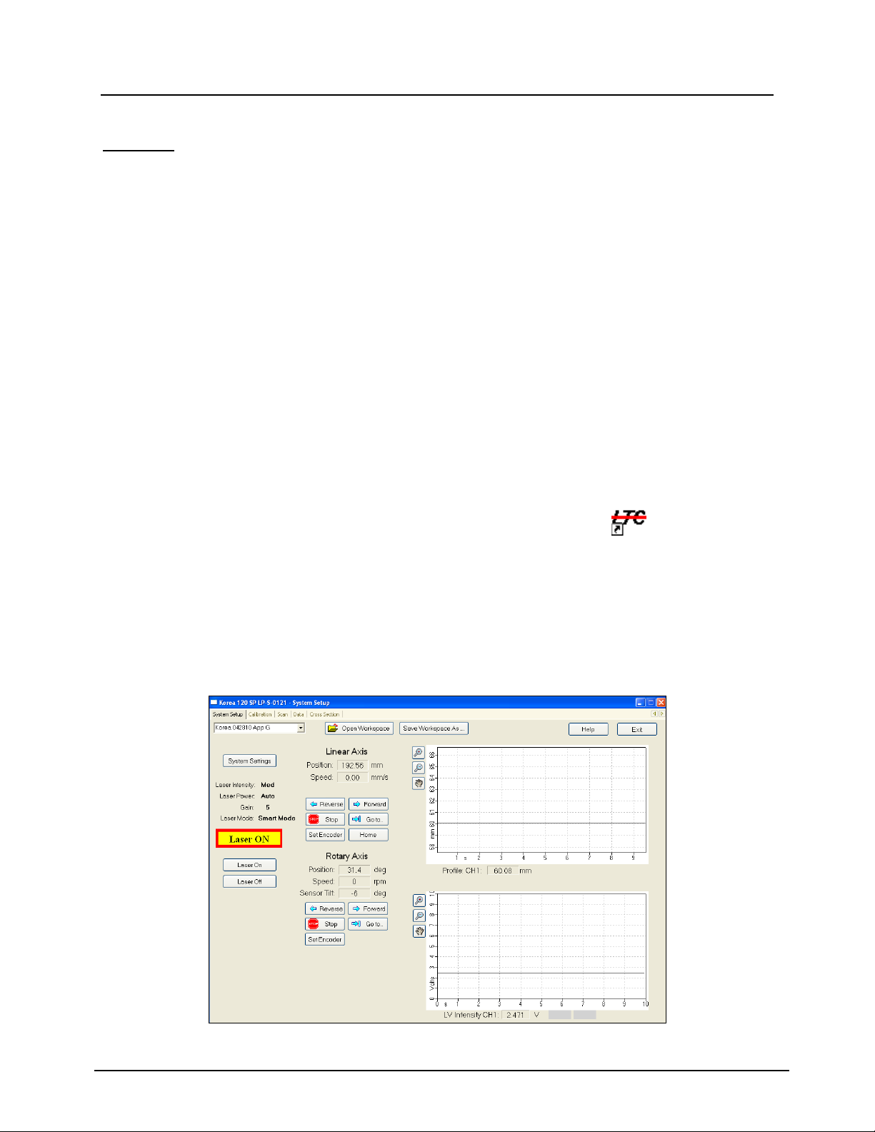
SYSTEM SETUP ..........................................................................................................................................................8
SYSTEM SETTINGS.....................................................................................................................................................9
Laser Power.........................................................................................................................................................9
Automatic.............................................................................................................................................................9
Fixed ....................................................................................................................................................................9
Laser Intensity.....................................................................................................................................................9
Gain .....................................................................................................................................................................9
Null......................................................................................................................................................................9
OPENING AND SAVING WORKSPACES......................................................................................................................10
Opening a Different Workspace .......................................................................................................................10
Saving a Workspace..........................................................................................................................................10
MOTOR AND AXIS CONTROL ...................................................................................................................................11
Driving Motors..................................................................................................................................................11
Moving to a Specified Location ........................................................................................................................11
Stopping Motors ................................................................................................................................................11
Setting Encoder Values.....................................................................................................................................11
SYSTEM CALIBRATION ............................................................................................................................................12
Initializing a Calibration Scan .........................................................................................................................12
If the Calibration Verification Process Passes.................................................................................................12
If the Calibration Process Fails........................................................................................................................13
Calibration Troubleshooting.............................................................................................................................14
SCANNING OPERATION............................................................................................................................................15
Setting the Scan Parameters.............................................................................................................................15
Advanced Scan Parameters................................................................................................................................15
Initializing a Scan .............................................................................................................................................16
VIEWING AND ANALYZING DATA............................................................................................................................17
Viewing Profile Data.........................................................................................................................................17
Opening Data Files............................................................................................................................................17
Data File Header ...............................................................................................................................................17
Color Plot Display .............................................................................................................................................18
Color Palette......................................................................................................................................................19
Changing the Magnification ..............................................................................................................................19
Viewing in 1:1 Aspect Ratio...............................................................................................................................20
Displaying Cross-Sectional Auxiliary Windows ................................................................................................20
Displaying Annotations......................................................................................................................................20
Viewing LaserVideo™ (LVI) Data ...................................................................................................................21
Data Analysis.....................................................................................................................................................22
Applying Processors to a Scan Data File ..........................................................................................................22
Processors..........................................................................................................................................................23
Reading Data Values .........................................................................................................................................25
Making point-to-point measurements.................................................................................................................25
Calculating Area/Diameter Statistics.................................................................................................................25
Viewing Cross Sectional Data...........................................................................................................................26
Selecting the Viewing Position...........................................................................................................................26
Selecting the Reference Radius ..........................................................................................................................27
Measuring the Radius/Diameter ........................................................................................................................27
Measuring Pit Depth..........................................................................................................................................27
Printing and Saving Data .................................................................................................................................28

2
Saving Processed Data ......................................................................................................................................28
Saving Text Files................................................................................................................................................29
Saving Bitmaps...................................................................................................................................................29
Printing ..............................................................................................................................................................29
USB KEY POWER ISSUE ..........................................................................................................................................30
Resolution ..........................................................................................................................................................30
QUICK REFERENCE SHEET.......................................................................................................................................31
TROUBLESHOOTING.................................................................................................................................................32
Laser..................................................................................................................................................................32
Motors................................................................................................................................................................32
Data ...................................................................................................................................................................33
Software.............................................................................................................................................................34

3
Laser Safety
The LP sensor system contains a Class IIIa laser: a visible, red laser diode with a
wavelength between 630-660nm and a maximum output power of 4.5mW. When used
according to these procedures, this product operates as a Class II laser product. The LP
data acquisition instrument is equipped with a SmartLaser™ mode that causes the laser
to turn on and off, with a maximum pulse length of 1.6ms and a frequency of 1Hz, when
a sample is not in range. The laser will only operate continuously when the sensor
detects a surface in range.
When the system is scanning inside closed-end tubes, LTC may setup the
LaserViewer™ workspace so that SmartLaser™ turns off during a scan of the sample,
and then automatically turns back on after the scan is ended. Scans should only be
performed when the sensor is inside a test sample or the provided calibration ring. This
procedure is required to operate as a Class II laser product.
No routine maintenance for the sensor needs to occur beyond keeping the system
generally clean. If fingerprints or other contamination are on the laser or photodetector
windows, make sure the system is off, then clean with an alcohol-based lens cleaner
and a lens cloth/tissue. For any other maintenance or service questions, contact LTC.
CAUTION
Use of controls or adjustments or performance of procedures other than those
specified herein may result in hazardous radiation exposure.
The sensor warning and ID/certification labels are located on the sensor.
Manufactured by: Model: DD-XXXX
Laser Techniques, LLC Serial #: LP-S-XXXX
Redmond, WA USA Mfd. Dec. 2008
Complies with USFDA 21CFR1040.10
<1mW @ 630-660nm
LASER APERTURE LABEL
AVOID EXPOSURE- Laser radiation is
emitted from this aperture.
ID/CERTIFICATION LABEL
SENSOR WARNING LABEL

4
Introduction
Overview
This manual is intended to provide the reader an introduction to the basic theory and application
of laser-based profilometry. It also includes specific instructions for the setup and operation of
the Laser MicroMap™ laser profilometry system (LP system).
The LP probe sensor employs the principle of optical triangulation using a 630 –680nm
wavelength visible diode laser. When operated in AUTO mode the LP system meets the Class II
requirements as set forth in FDA - 21 CFR 1040.10. In TEST mode (intended for maintenance
only) the system is classified as a Class IIIa laser product.
Although this document is intended to provide sufficient instructions for the operation and use of
the LP system, on-site training is advised to augment the information contained herein.
System Configuration
The Field-Grade Laser MicroMap™ system is typically comprised of three elements: the LP-
4210F™ data acquisition and control instrument (which also houses the motor control unit), a
sensor, and a sensor delivery unit. In addition, all inspection systems have a calibration fixture
that is either external to the system or integrated into the sensor delivery unit. The following is a
brief description of each of the basic elements of a system. For more information regarding each
element for a specific application, refer to the Addendum that is provided with each system.

5
LP-4210F™ Data Acquisition Instrument
The LP-4210F™ provides controls for all motion of the sensor, laser power control, analog
signal processing, and data acquisition and analysis capabilities.
Front Panel Controls
POWER –A red LED that indicates power ON/OFF.
LASER –An indicator light that illuminates yellow when the sensor control board is powered
and red when the laser is emitting light.
SENSOR –A two-position, key-lockable switch that controls the laser diode with OFF and ON
settings. In the OFF state, there is no power to the sensor control board. Use this setting when
plugging or unplugging the sensor from the LP-4210F™ unit.In the ON state, the sensor control
board is powered up, and the laser can be nulled and turned on using LaserViewer™ software.
MOTOR POWER –The LP-4210F™ houses a Motor Control Unit (MCU). This unit is often
custom-configured according to the client’s application. The Motor Power switch turns
ON/OFF the MCU. The switch will illuminate red when the MCU is ON. To prevent moving
the sensor accidentally, turn the MCU OFF when not driving the motors or scanning.
USB –Two USB 2.0 ports.
Figure 1. LP-4210F™ Front Panel

6
Rear Panel Controls
MOTOR FUSE 2.5AMP –The MCU uses a 2.5A time delay fuse.
MOTOR and SENSOR –The Linear Motor Cable and Sensor Cable attach to these connectors.
EXT MONITOR –An external VGA monitor may be plugged into this connector. When using
an external monitor, the image quality on the internal monitor may degrade significantly.
ETHERNET –A Category 5e Ethernet port for the data acquisition system.
USB –Two USB 2.0 ports.
100-240VAC (50/60Hz) FUSE 4AMP –The power supply is rated for 100-240VAC (50/60Hz),
and will automatically detect the voltage input level at the power module. LP-4210F™is
provided with a 4A fused rocker-type momentary power switch.
Motor Control Unit
The LP-4210F™ system is provided with an internal Motor Control Unit. This unit is custom-
configured according to each customer’s application, and is not accessible by the customer.
Figure 2. LP-4210F™ Back Panel

7
Delivery System
The LP system may include a sensor delivery system. This unit is often custom-configured
according to each client’s application. The attached Addendum contains provides a detailed
description of the delivery system, if included.
LaserViewer™ 2010 Software
To open LaserViewer™2010, double-click on the LaserViewer™ 2010 icon on the desktop, or
choose Programs, LTC, LaserViewer ™2010 from the Start Menu.
LaserViewer™ 2010 will not operate if the software key is not attached to one of the USB ports
on the LP-4210F™ before starting the software.
If LaserViewer™ 2010 is started without the software key, the program must be closed, then re-
opened after the key is in place.

8
System Setup
Important
All instruments in the system should be plugged into the same circuit to insure a common
ground.
Always confirm that the power is OFF to all instruments, including the Motor Controller
Unit, before attaching or detaching cables.
When attaching or detaching cables only grasp the outer ring of the connector. DO NOT
grasp and rotate the main body of the connector.
1. Attach all cables and the sensor as shown in the Addendum.
2. Confirm that the LP-4210F™ is plugged into a fused and surge-protected power source
that provides 100 –240 VAC at 50 to 60 Hz.
3. Confirm that the SENSOR key switch and the MOTOR POWER switch are in the OFF
position.
4. Ensure that the LaserViewer™USB Key is in a USB port.
5. Turn the LP-4210F™ ON, and double-click the LaserViewer icon on the desktop.
6. Click the System Setup tab.
7. Verify that the workspace name is correct. If not, click the Open Workspace button and
click on the correct workspace for the application (Figure 3).
8. Turn the SENSOR key switch on for at least 5 minutes before proceeding with
calibration. This allows the internal electronics to warm up and will minimize any
temperature-related drift in calibration.
Figure 3. System Setup Tab

9
System Settings
Open the System Settings window from the System Setup tab (Figure 3).
Note: The default settings are recommended. The System Settings window is intended
primarily for test purposes.
Laser Power
Automatic
This is the default setting. In Automatic mode, the laser is under control of an embedded laser
driver that is housed in the sensor module. In this mode the system employs Automatic Gain
Control (AGC), and the laser output will vary between 10% and 90% of full rated power,
depending on the surface reflectivity of the target.
Fixed
Fixed mode is Manual Gain Control (MGC). In Fixed mode the Laser Intensity buttons control
the laser output power, and the Gain buttons control the amplification (gain) of the normalized
analog voltage signal from the sensor.
Laser Intensity
The Laser Intensity buttons control the laser output power in Fixed mode. The Low, Med, and
High settings typically correspond to 20%, 50% and 100% of full rated power, respectively. The
precise laser power output for each setting is set by the manufacturer.
Gain
The Gain buttons control the amplification (gain) of the normalized analog voltage signal from
the sensor. Each interval of Gain (1, 2, 5, 10, 20, 50, 100) is the factor by which the LVI signal
increases.
Null
The Null button is used to balance the amplifier offsets for individual sensors. This button is
used primarily for testing, as the sensor will auto-null before scans.
Figure 4. System Settings

10
Opening and Saving Workspaces
LaserViewer™ Workspaces contain all of the setup information necessary to perform scans or
analyze data. This system has been provided with one or more pre-configured Workspaces that
have been tailored to your application. However, it may be convenient to save several different
Workspaces, each with different pre-set scan and processing parameters, to facilitate acquiring
and analyzing different types of scans (e.g. large low-resolution scan vs. small high-resolution
scan).
Note: LaserViewer™ automatically opens the Workspace that was open when it was closed last.
Opening a Different Workspace
Click on the Open Workspace... button on the System Setup tab, then browse to the new
Workspace.
If the desired Workspace is in the same folder as the current Workspace, click the down arrow
next to the Workspace name on the System Setup tab, then select the new Workspace.
Saving a Workspace
Click on the Save Workspace As... button on the System Setup tab, then browse to the desired
folder and type the new Workspace name.
Important: Do not overwrite the Workspaces provided with this system. Once a Workspace file
has been overwritten, it cannot be returned to its previous state. However, a backup folder has
been included with the original Workspace(s) and variable file(s).

11
Motor and Axis Control
Driving Motors
Click on the Forward or Reverse button on the System Setup tab. One click will produce slow
motion, two clicks will produce faster motion, and three clicks will provide the fastest motion.
Moving to a Specified Location
1. Click on the Goto.. button for the appropriate axis on the System Setup tab.
2. Type the desired location and speed.
3. Click Goto.
Important: Always pay close attention to motors while they are moving to prevent collisions
between the sensor and other objects.
Stopping Motors
Click the Stop button for the appropriate axis on the System Setup tab. This will stop only the
specified motor. Any other motors in motion will continue moving.
To stop all motion, press the Space Bar.
Setting Encoder Values
1. Click the Set Encoder button on the System Setup tab.
2. Type the new encoder value.
3. Click OK.
Important: Every time the system reset is turned on or reset, the zero position must be reset. If
the encoders are zeroed anywhere except at the specified zero positions, then pre-set moves and
scans will not go to the correct positions. Damage to the sensor may result. Each system has a
specified zero position for the sensor. See the Addendum: System Setup for information about
this system.

12
System Calibration
Initializing a Calibration Scan
Note: Refer to the Addendum provided with this manual for calibration setup and scanning
instructions specific to your system.
1. Insert the sensor into the cal fixture, and initialize the encoders as described in the
Addendum.
2. Click the Calibration tab.
3. Click the Start Scan button.
If the Calibration Verification Process Passes
If the Pass/Fail indicators all display green and indicate PASS, the system is properly
calibrated and ready for operation.

13
If the Calibration Process Fails
1. Click the Adjust Cal correction button. (Figure 5)
This will modify the calibration parameters and, in most cases, allow the system to properly
calibrate.
2. Press Rescan to recalibrate the system.
3. If the calibration sequence is successful (three green PASS boxes), click the System
Setup tab.
4. Move the sensor backwards out of the Calibration Ring, and remove the Calibration
Ring.
5. Click the Scan tab and setup a scan as described in the Error! Reference source not
found. section.
In most cases, the system will calibrate in one or two attempts. If the system will not calibrate
after three attempts, check the Calibration Troubleshooting section.
Figure 5. Adjust Calibration

14
Calibration Troubleshooting
Confirm that all three rings appear in the plot (Figure 6). If they do not, attempt to reset
the home position by pressing Start Scan, and following the instructions.
Verify that each of the three annotations is centered in its respective ring (Figure 6). If
not, their positions can be adjusted in Advanced Parameters under Ring X Analysis
Start.
Check that bright lights were not shining on the sensor during the scan.
If there is a large error message, press Restore Defaults from the Cal Parameters
window, and rescan.
Check the Cal Ring Tolerance in the Cal Parameters window. This value should not be
less than 0.01mm. If one or two rings pass, but not all three in 3 or more attempts, the
Cal Ring Tolerance may need to be increased to 0.02mm.
Note: Large slope errors may require more than one correction. Offset errors and small slope
errors are typically corrected in a single iteration.
If the Accept AutoCal Correction button is pressed when the calibration procedure has not been
performed correctly, large errors in calibration may result. If the calibration parameter errors are
so large that the calibration ring becomes out of range, the error is not correctable and the backup
calibration parameters should be loaded. This can be done by clicking the Restore Defaults
button from the Cal Parameters window, and then pressing Save.
Figure 6. Calibration Alignment
The annotations should be centered within the rings.

15
Scanning Operation
Note: Refer to the Addendum provided with this manual for scanning instructions specific to
your system.
Setting the Scan Parameters
1. Click the Scan tab.
2. Click the Scan Parameters button to set the desired inspection parameters.
3. Set the desired scan length and resolution.
4. Click the Update button and confirm that the scan time, resolution, file size, and other
parameters are acceptable.
Note: It is recommended that files sized be kept below 250 MB and the data rate below 120
kHz. A warning will be displayed in the Scan Parameters window if either value exceeds these
set maximums. Decrease the Rotary Speed if the Data Rate is too high (Maximum is 600 rpm).
Advanced Scan Parameters
Advanced Scan Parameters can be accessed by clicking Advanced in the Scan Parameters
window. The factory settings generally should not be changed, but the following parameters
may be practical for varying scan requirements.
In Helical scan mode, the sensor is continuously drawn through the component as the
sensor rotates. This generates a helical scan pattern. This mode is most useful when high
resolution scanning (axial spacing 1-2mm or 0.04-0.08 inches).
In Incremental mode, the sensor continuously rotates but the linear axis steps from
position to position. This mode of operation is most useful when scanning large axial
spaces (>2mm or 0.08 inches). Incremental scans generally take longer than helical
scans.
SmartLaser™On/Off toggles between Smart Laser™ and Continuous Laser modes.
SmartLaser™ is the laser safety mode. When the sensor does not detect a surface in its
measuring range, the laser pulses at a low average power at a rate of 10 Hz until a surface
is detected. In Continuous mode, the laser is always on. This mode is intended for
maintenance only.

16
Figure 7. Scan Tab
Figure 8. Scan Parameters
Initializing a Scan
Important: The Home position should be verified immediately prior to each scan to ensure
positional accuracy. This procedure will reduce small axial position errors that can accumulate
as the system is driven forward and reverse multiple times in one session.
1. Click the Start Scan button on the Scan tab to initiate a scan sequence.
2. When the scan is complete, a save prompt will appear. Save the data to the appropriate
folder for later analysis. (Refer to the Printing and Saving section.)

17
Viewing and Analyzing Data
There are three data plots that enable operators to view and analyze data: the Profile plot, the
LVI plot, and the Cross Section plot. The Profile plot displays a color plot of the profile data.
The LVI plot displays the LaserVideo™ Image (total detected light at each point) of the scan.
The Cross Section plot displays cross-sectional slices of the profile data.
Viewing Profile Data
Opening Data Files
1. Click the File button on the Data tab, and then click Open File.
2. Browse to the folder that contains the file.
3. Click on the filename, and press Open.
Data File Header
Each data file contains header information, which includes the scan axis range, length and
resolution; the index axis range, length and resolution; the number of data subsets; and the data
type and range for each subset.
Click the File button from the Scan tab to access the file options, then the View Header
button to view the profile data header information.
Figure 9. Data Tab

18
Color Plot Display
The color plots in the Scan and Data tabs may be used to display live scan data and saved data,
respectively.
Color Plot image from LaserViewer™
3D Barrel image from LaserViewer3D™
Figure 10. Color Plot Display
The color plot displays a 2-dimensional image of
the inside of the scanned object. The vertical
axis is the axial position, while the horizontal
axis is the angular position. The colors of the
plot represent radii, and can be set by the color
palette in the upper left side of the screen (See
the Color Palette section below).

19
Color Palette
The Palette Painting window has several palettes that may be painted. In addition, moving the
cursor over the palette causes a histogram of the displayed data to appear above the palette.
1. Double-click on the palette display to the left of the color plot to activate palette painting.
2. In the Palette Painting window, right or left click on the desired color palette. Right
clicking sets the lower palette, and left clicking sets the upper palette. Jet is typically
used for Profile data, and Grey is typically used for LaserVideo™ Images.
3. If the Paintbrush icon is not highlighted (turns blue), click it to enable painting.
4. Move the cursor to the palette display above the color plot. The cursor will turn into a
paintbrush when it is over the palette display. If the cursor does not turn into a
paintbrush, click the Paintbrush icon.
5. Right or left-click and drag the paintbrush cursor over the portion of the palette to be
changed. Left-clicking paints the upper palette in the Palette Painting window, while
right-clicking paints the lower palette. The color plot will update immediately.
6. If desired, click Load to open a previously saved palette, and Save to save a palette.
Changing the Magnification
To zoom in to a selected area of data
1. Click the Zoom In icon.
2. Click and drag the cursor over the data to be magnified.
To return to the lowest magnification
Click the Zoom Out icon.
To move the viewed area in a zoomed color plot
1. Click the Pan icon.
2. Click and drag on the color plot.
Figure 11. Color Palette
Table of contents