4
Inspection Camera Kit 22mm
CAM1095
• Use only accessories that are recommended by
the manufacturer for your equipment. Accesso-
ries that may be suitable for one piece of equip-
ment may become hazardous when used with
other equipment.
• Do not force equipment. Use the correct equip-
ment for your application. The correct equipment
will do the job better and safer at the rate for
which it is designed.
• Practice good hygiene. Use hot, soapy water to
wash hands and other exposed body parts ex-
posed to drain contents after handling or using
drain inspection equipment. Do not eat or smoke
while operating or handling drain inspection
equipment. This will help prevent contamination
with toxic or infectious material.
• TurnOFFcamerawhennotinuse.Thiswillprolong
the unit’s life and avoid excessive heat build-up.
Servicing And Repairs
Have your equipment serviced by a qualied
repair person using only identical replacement
parts. This will ensure that the safety of the
equipment is maintained. This will also deter-
mine your warranty claim in the event of equip-
ment failure.
SPECIFIC SAFETY RULES
Do not use tool if switch does not turn it ON or
OFF. Any tool that cannot be controlled with the
switch is dangerous and must be repaired.
• Be sure that the unit is plugged into a properly
grounded outlet. If in doubt, check the outlet be-
fore plugging in the machine. Check the power
cord to see that there are no cuts or frays, and
that the grounding prong on the plug is still in
place.
• If the power cord supplied with the machine is
not long enough. Be sure to use the 3m or 5m
patch cables which are supplied
• Be careful when cleaning drains where cleaning
chemicals have been used. Avoid direct contact
with corrosive drain cleaners. Drain cleaning
chemicals can cause serious burns, as well as
damage the cable. Neutralize or remove corro-
sive drain cleaners in the drain before starting
the job.
• Protect against excessive heat. The product
should be situated away from heat sources such
as radiators, heat registers, stoves, or other
products (including ampliers) that produce heat.
EQUIPMENT OVERVIEW
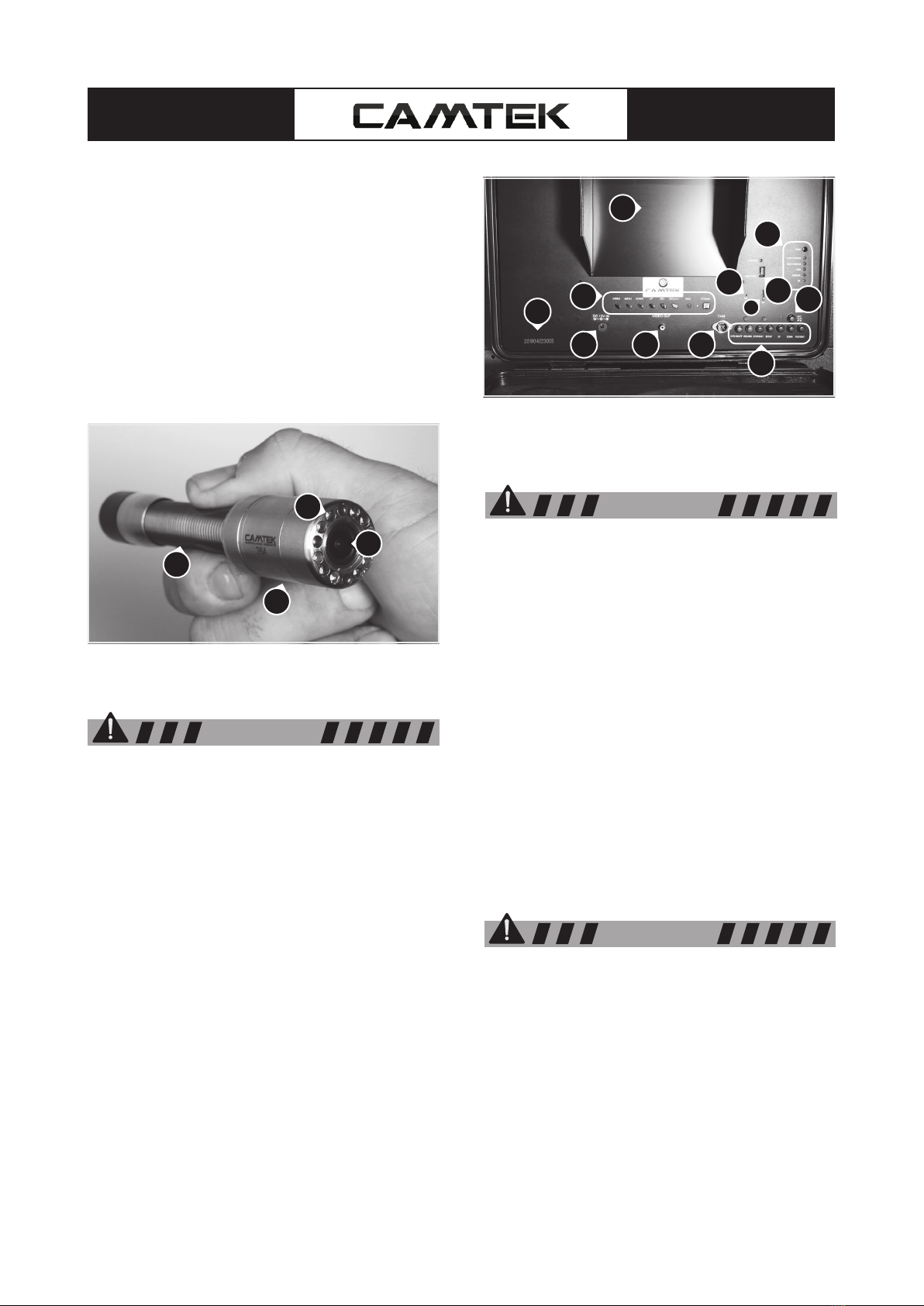
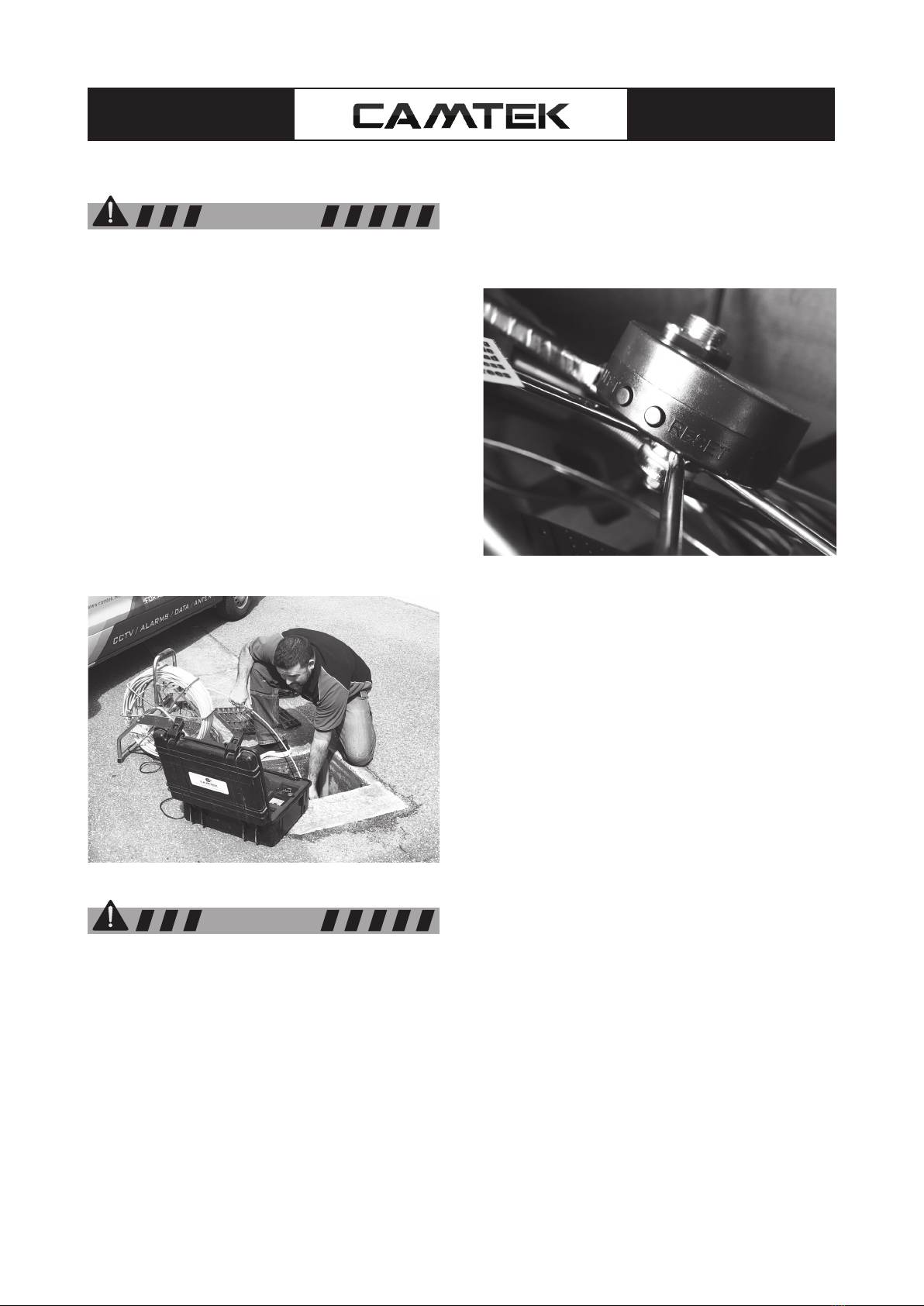
Camera
• The camera, although manufactured for the
harsh environments in which it will be used,
should be treated carefully as damage may
occur if dropped or KNOCKED severely
against the pipe or any other hard surface.
The stainless-steel camera housing is made to
protect the camera and electronics to a large
extent; however, it can be damaged by denting
which may cause possible failure of the protec-
tive and watertight O-ring seals that may cause
the camera to fail.
• The camera housing, and front viewing lens
should be checked thoroughly after each use
for signs of damage and if required should be
corrected prior to further use.
• The camera should always be cleaned and
inspected after every use as dirt, grime and
grease can cause unnecessary problems such
as failure of the camera seal.
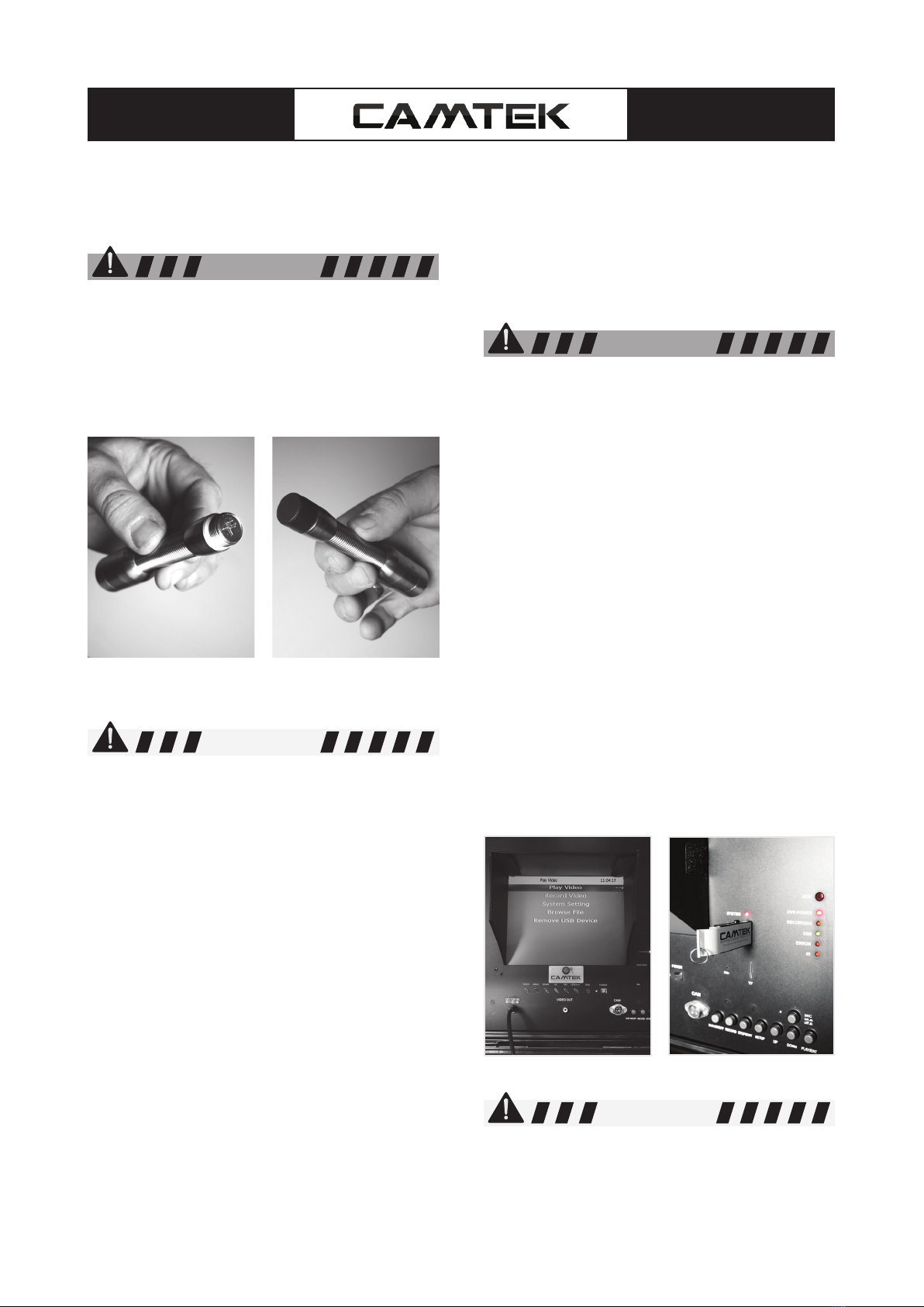
• The standard camera spring is attached to the
cable via stainless steel hex socket cap screws.
This connection includes an O-ring, sealing the
connection from water leakage. This connection
should be checked after every use to ensure
that the screws have not loosened during the in-
spection
• If disconnecting the camera from the push rod,
make sure that the O-ring is in good condi-
tion and/or replaced when replacing the camera
onto the push rod.
• The camera lens, front nose piece and lights
should be cleaned and checked after every
use for possible damage to the lens or light
covers and to prevent a build-up of dirt and
grime which may cause a degradation of the
video picture.
NOTICE
NOTICE
WARNING