LTI DI-FT Series Manual

2022
OPERATION/MAINTENANCE MANUAL
CUSTOM FABRICATORS OF FOODSERVICE EQUIPMENT
1947 Bill Casey Parkway ● Jonesboro, GA 30236
Tel: 1 (888) 584-2722 ● Fax: 1 (770)-471-3715
www.lowtempind.com
DI-FT
FT SERIES
FROST TOP SYSTEM

2022
Table of Contents
INSPECTION ........................................................................................................... 3
SAFETY PRECAUTIONS........................................................................................ 3
INSTALLATION INSTRUCTIONS ............................................................................... 5
OPERATING INSTRUCTIONS ................................................................................... 6
START UP ........................................................................................................... 6
OPERATION........................................................................................................ 7
CLEANING INSTRUCTIONS.................................................................................... 10
PREVENTATIVE MAINTENANCE............................................................................ 11
TROUBLESHOOTING............................................................................................. 12
REPLACEMENT PARTS .......................................................................................... 13
DIAGRAMS........................................................................................................... 14
WARRANTY.......................................................................................................... 19

3
INSPECTION
Upon receipt, the crate should be inspected for visual damage. Any damage should be
reported immediately to the carrier.
SAFETY PRECAUTIONS
This manual includes safety and operating instructions for Frost Top (FT) series system. LTI
recommends reading all safety precautions and statements to ensure safe operation before
installing and operating. Below are the precautions that are explained in more detail. Please
read carefully.
DANGER
Danger warns of imminent hazard which will result in serious injury or death.
WARNING
Warning indicates the presence of a potential hazard or unsafe practice that will or can
cause severe personal injury or death.
CAUTION
Caution indicates the presence of a hazard or unsafe practice that will or can cause minor
or moderate personal injury if the caution is ignored.
NOTICE:
Used to note information that is important but not hazard-related.

4
WARNING
ELECTRIC SHOCK HAZARD
•Unit must be installed by a qualified
electrician. Installation must
conform to all local electrical codes.
In the absence of local codes, use
the latest version of the National
Electrical Code.
•Unit should be safely and
adequately grounded in accordance
to local codes, or in the absence of
local codes, the most up to date
version of the National Electrical
Code ANSI/NFPA70, to protect the
user from electrical shock.
•The unit requires a grounded system
and a dedicated circuit.
•The unit must be serviced by
qualified personnel only. Service by
unqualified personnel may lead to
electric shock or burn.
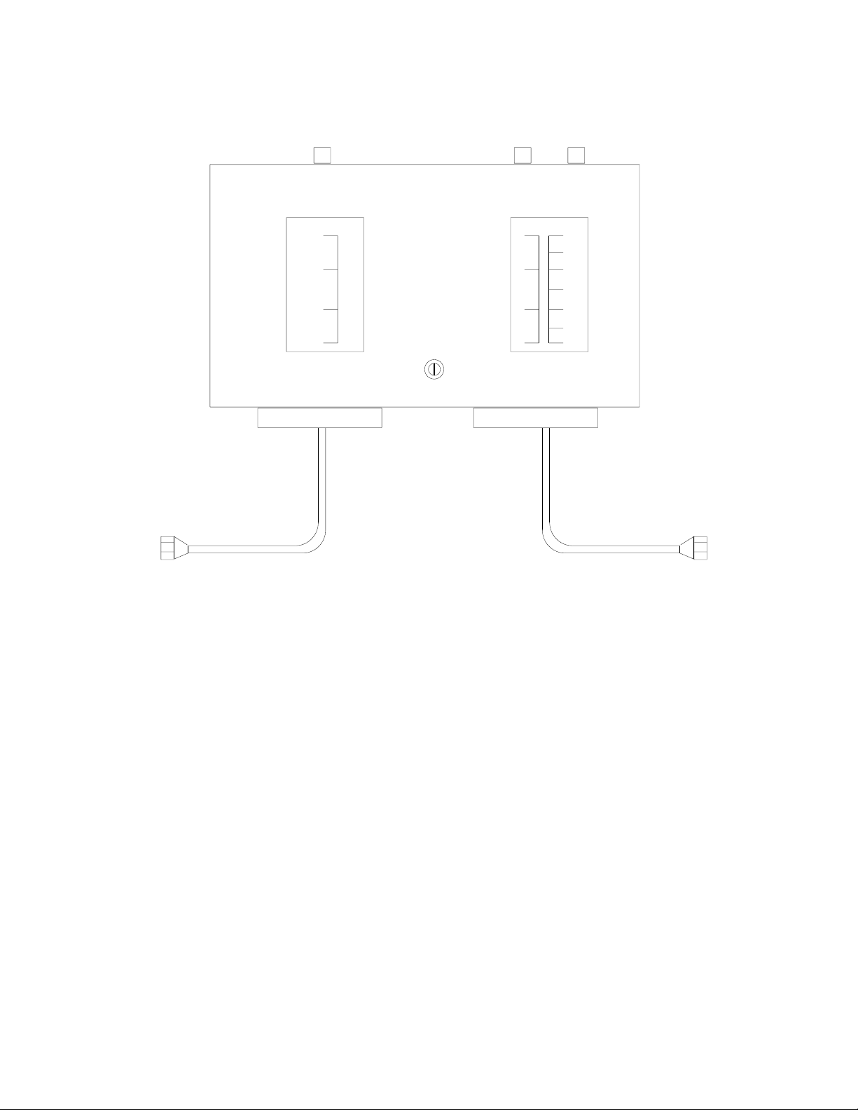
•Control panel must be mounted on a
vertical surface/wall and installed in
the vertical position. Mounting
control panel in the horizontal
position may result in collection of
liquids and lead to electrical shock.
•Turn OFF power, unplug power
cord/turn off power at circuit
breaker, and allow unit to cool if
needed to before performing any
cleaning, adjustments, or
maintenance.
•Do not use flammable cleaning
solutions to clean this unit.
NOTICE:
•Units are voltage specific. Refer to
specifications label for electrical
requirements before installation.
•Use non-abrasive cleaners and
cloths only. Abrasive cleaners and
cloths could scratch finish of unit,
marring its appearance and making
it susceptible to soil accumulation.
•Do not use steel wool for cleaning.
•Do not use harsh chemicals such as
bleach, cleaners containing bleach,
or oven cleaners to clean this unit.

5
INSTALLATION INSTRUCTIONS
LTI FT Series are self-contained units designed for short term display and of food and desserts.
The units are designed to help maintain product temp for short periods of time and are
dependent upon the ambient temperature in which they are installed and product temperature
when it is placed in the unit. Products should be carefully monitored and rotated as necessary
to meet local health requirements.
When installed adequate air flow must be provided to ensure proper operation. Thru air flow is
required but if not, exhaust fans should be used to ensure adequate heat exhaust. Connect the
unit into the proper grounded electrical service. Refer to unit’s electrical data tag for correct
electrical service requirements and refrigeration information. The unit is now ready for
operation. Refer to figure for dimensions and overall details.
*** WARNING ***
To prevent any electrical accidents, this equipment should be installed and serviced by
qualified maintenance personnel only per national electrical code standards.

6
L
2" 2"
L'
24" OR *18"*
2"
2" 20" I.S.
OR
*18" I.S.*
4"
143
4"
183
4"
3"
183
4"
4"
143
4"
PLAN VIEW
1
2"
24" OR *22"*
1
2"
3
4"
3
4"
3/4"
OPEN
DRAIN
3/4"
OPEN
DRAIN
OPERATING INSTRUCTIONS
START UP
The refrigeration system supplied with these systems are of the hermetic type. Refrigerant is
metered by expansion valves which are located in the compressor housing of frost top (FT) unit.
Each refrigeration system is self-contained and has been leak tested, charged with refrigerant,
and operated to ensure the proper operation and setting of the controls.
Energize the unit by attaching the plug to an appropriate electrical supply (115 vac, 60 hz, single
phase, 12 amp) and turning on the service switch located in the compressor compartment.
Prep the unit for use by allowing the unit to run approximately one (1) hour before displaying
product.
Model #
Unit
Length
L
FT
Length
L’
Cut-Out Size
Comp.
Volts/
Phase
Amps
(120V)
NEMA
Plug
DI-FT-18-26-X
30”
26”
21 1/4 X 29 1/4
1/3
120V/1
7.0
5-15
DI-FT-20-25-X
29”
25”
23 1/4 X 28 1/4
1/3
120V/1
7.0
5-15
DI-FT-20-38-X
42”
38”
23 1/4 X 41 1/4
1/3
120V/1
7.0
5-15
DI-FT-20-51-X
55”
51”
23 1/4 X 54 1/4
1/3
120V/1
7.0
5-15
DI-FT-20-64-X
68”
64”
23 1/4 X 67 1/4
1/3
120V/1
7.0
5-15
DI-FT-20-77-X
81”
77”
23 1/4 X 80 1/4
1/3
120V/1
7.0
5-15

7
OPERATION
The system temperature is controlled by the pressure control which is located inside the
compressor housing. The TXV metering device controls the flow of refrigerant to the evaporator
of the unit.
The low pressure control (physically located in the front of the compressor compartment) is
used to cycle off the compressor. The low pressure control should not be adjusted from the
factory settings. Adjustment of this control may cause performance problems with the unit.
Factory Settings for Frost Top (FT) Units:
•Cut-In –40psi
•Cut-Out –15psi
•Differential - 25
For instructions on setting Pressure Controls see illustrations provided.

8
DIGITAL PRESSURE CONTROLLER
35 PSI
START
SET
SET SERVICE
UP & DOWN
START
ALARM MENU
•SET –To display target set point, in programming mode it selects a parameter or
confirm an operation.
•START- (RESTART) It depends on the rSC parameter; with rSC=rSt it allows a manual
restart and ad “dead band reset”; with rSC=nP only the dead band reset is allowed.
•(UP) –To see the condenser temperature for 5sec; in programming mode it browses the
parameter codes or increases the displayed value.
•(DOWN)- To see the dLt temperature; in programming mode it browses the parameter
codes or decrease the displayed value.
•(SERVICE)- To enter the service menu.
•(ALARM MENU)- To enter the Alarm menu.
How to Modify Set Point:
1. Press and hold down the SET key unit PSI begins to blink. Display will show Cin.
2. Press and release the SET key to display its value.
3. Use the UP or DOWN to change the value.
4. Push and immediately release the SET key: the display will show Cou.
5. Press and release the SET key to display its value.
6. Use the UP or DOWN to change the value.
7. Press the SET key save and to return to the suction pressure display press the SET + Up
arrow at the same time.

9
MECHANICAL PRESSURE CONTROL
150
250
350
450 10
20
30
40
100
80
60
40
20
0
10"
RANCO MODEL 012-4834-000 DUAL PRESSURE CONTROL
NUMBER OF POLES: 1
CONTACT ACTION:
(CONTROL LOW PRESS. SIDE) OPEN ON LOW, CLOSE ON HIGH
(SAFETY HIGH PRESS. SIDE) CLOSE ON HIGH, OPEN ON LOW
LOW PRESSURE SIDE
CUT-IN SETTING RANGE: 10" MERCURY VAC TO 100 PSI
DIFFERENTIAL: 10 TO 40 PSI
HIGH PRESSURE SIDE
CUT-OUT RANGE: 150 TO 450 PSI
DIFFERENTIAL: 70 PSI
AC FULL LOAD AMPS 24
REFRIGERANT CONNECTIONS: 1/4" FEMALE FLARE, 36" CAPILARY

10
CLEANING INSTRUCTIONS
To maintain the performance and finish of the unit clean the unit daily. Make sure to use
cleaning supplies and cleaners designed for cleaning stainless-steel surfaces.
Stainless steel:
Use soft cloths, microfiber, sponges, or plastic scouring pads. Avoid using scrapers wire brushes,
steel wool or anything that might scratch the surface. Always clean stainless-steel parallel with
the “grain”. Use cleaners that contain alkaline, alkaline chlorinated, or non-chloride chemicals.
CONDENSER COIL
WARNING: Always disconnect power before inspecting or cleaning condenser coil. Never use
high-pressure water to clean condenser coil as water can damage electrical components
located near the condenser coil.
The condenser coil requires adequate cleaning to maintain proper operation which is
recommend every 90 days. If debris is more prevalent the condenser coil should be cleaned
every 30 days. Neglecting the condenser coil cleaning procedures will void any warranties
associated with the condensing unit or cost to replace the compressor

11
PREVENTATIVE MAINTENANCE
To ensure that your equipment will continue to operate properly follow these simple steps.
•The unit should be cleaned thoroughly every day. Excess food spillage left can cause
damage to the unit. Where applicable clean unit daily.
•Make sure condensing unit has adequate air flow to prevent overheating. Thru air flow
is required but if not, exhaust fans should be used to ensure adequate heat exhaust.
Properly shrouding condenser inlet air flow is recommended to provide fresh air across
condenser.
•Make sure that the condenser is kept clean of dust and dirt and if filter is provided
change every 30-90 days. Failure to do this will cause compressor to overheat and may
cause compressor failure and will VOID ANY FACTORY WARRANTY on compressor.

12
TROUBLESHOOTING
REFRIGERANT TROUBLESHOOTING
COMPLIANT
PROBLEM
SOLUTION
COMPRESSOR WILL NOT START
LINES DISCONNECTED / SWITCH OPEN
CLOSE START ON DISCONNECT SWITCH
FUSE REMOVED OR BLOWN
REPLACE FUSE
CONTROL STUCK IN OPEN POSITION
REPAIR OR REPLACE CONTROL
CONTROL OFF DUE TO COLD LOCATION
RELOCATE CONTROL
COMPRESSOR WILL NOT START, HUMS
BUT TRIPS OVERLOAD PROTECTOR
LOW VOLTAGE TO UNIT
CALL POWER SUPPLIER
STARTING CAPACITOR DEFECTIVE
REPLACE CAPACITOR
RELAY FAILING TO CLOSE
REPLACE RELAY
COMPRESSOR MOTOR HAS A WINDING
OPEN OR SHORTED
REPLACE COMPRESSOR
INTERNAL MECHANICAL TROUBLE IN
COMPRESSOR
REPLACE COMPRESSOR
COMPRESSOR STARTS AND RUNS, BUT
SHORT CYCLES ON OVERLOAD
PROTECTOR
LOW VOLTAGE TO UNIT
CALL POWER SUPPLIER
OVERLOAD PROTECTOR DEFECTIVE
CHECK CURRENT, REPLACE PROTECTOR
RUN CAPACTIOR DEFECTIVE
REPLACE CAPACITOR
EXCESSIVED DISCHARGE PRESSURE
CHECK VENTILATION, RESTRICTIONS IN
COOLING MEDIUM, RESTRICTIONS IN
REFRIGERANT SYSTEM
COMPRESSOR TOO HOT, RETURN GAS
HOT
CHECK REFRIGRANT CHARGE (FIX LEAK IF
NECESSARY)
COMPRESSOR MOTOR HAS A WINDING
SHORTED
REPLACE COMPRESSOR
UNIT RUNS OKAY, BUT SHORT CYCLE ON
OVERLOAD PROTECTOR
CHECK CURRENT, REPLACE PROTECTOR
THERMOSTAT
DIFFERENTIAL SET TO CLSE, WIDEN
HIGH PRESSURE CUT OUT DUE TO:
INSUFFICIENT AIR, OVERCHARGE, OR AIR
IN SYSTEM
REDUCE REFRIGERANT CHARGE, PURGE.
CHECK AIR SUPPLY TO CONDENSER,
REDUCE REFRIGERANT CHARGE, PURGE
UNIT OPERATES LONG OR
CONTINUOUSLY
SHORTAGE OF REFRIGERANT
FIX LEAK, ADD CHARGE
CONTROL CONTACTS STUCK OR
FROZEN/CLOSED
CLEAN CONTACTS, OR REPLACE CONTROL
REFRIGERANT OR AIR CONDITIONED
SPACE HAS EXCESSIVE LOAD OR POOR
INSULATION
DETERMINE FAULT AND CORRECT
EVAPORATOR COIL ICED
DEFROST
RESTRICTION IN REFRIGERANT SYSTEM
DETERMINE LOCATION AND REMOVE
DIRTY CONDENSER
CLEAN CONDENSER
FILTER DIRTY
CLEAN OR REPLACE
START CAPACITOR OPEN
RELAY CONTACTS NOT OPENING
PROPERLY
CLEAN CONTACTS OR REPLACE IF
NECESSARY
PROLONGED OPERATION ON CYCLE DUE
TO LOW VOLTAGE, IMPROPER RELAY
CALL POWER SUPPLIER, OR REPLACE
RUN CAPACITOR OPEN, SHORTED OR
BLOWN
EXCESSIVE SHORT CYCLE
DETERMINE REASON FOR SHORT CYCLE
IMPROPER CAPACITOR
DETERMINE CORRECT SIZE AND REPLACE
EXCESSIVELY HIGH LINE (100% OF RATED-
MAX)
CALL POWER SUPPLIER
SPACE TEMPERATURE TOO HIGH
CONTROL SETTING TO HIGH
RESET CONTROL
INADEQUATE AIR CIRCULATION
IMPROVE AIR MOVEMENT
SUCTION LINE FROSTED OR SWEATING
EXPANSION VALVE STUCK
CLEAN VALVE OFF FOREIGN PARTICLES,
REPLACE IF NECESSARY
EVAPORATOR FAN NOT RUNNING
DETERMINE REASON AND CORRECT
OVERCHARGE OF REFRIGERANT
CORRECT CHARGE

13
REPLACEMENT PARTS
ITEM NO.
DESCRIPTION
STOCK NO.
MFG NO.
MANUFACTURER
1
CONDENSING UNIT
311937
AE2420-AA1BXM
(BOM-2E294-1)
TECUMSEH
1A
CONDENSING UNIT
311936
AE2415Z-AA1ASC
(BOM-32F328-59S)
TECUMSEH
2
COMPRESSOR
AE2420Z-DS1B
311937
AE1322E-679-J7
TECUMSEH
2A
COMPRESSOR AE2415-
AA1A
311936
BM AE1157E-679-J7
TECUMSEH
4
PRESSURE CONTROL
280610
012-4834-000
RANCO
5
DIGITAL PRESSURE
CONTROL
311938
TECUMSEH
P/N-900-11968
DIXELL
6
FILTER DRIER
282310
C-052-S-T-HH
SPORLAN
7
SIGHT GLASS
282400
SA-12S
SPORLAN
8
ACCUMULATOR
281700
3616
REFRIG.
RESEARCH
8A
ACCUMULATOR
102-10034
TECUMSEH
9
TXV-507
282572
Y1017-FP-1/6ZP
SPORLAN
9A
TXV-449
282586
EFD-1/5-ZP 2SX4 ODF 30
SPORLAN
10
LIQUID LINE SOLENOID
281610
E3S120W
SPORLAN
12
ROCKER SWITCH 2PL-
20A/277V
335917
TIGK721-6S-BL-NBL-
20A/277V
CARLING

14
DIAGRAMS
DI-FT WIRING DIAGRAM
WIRING DIAGRAM FOR DI-FT REFRIGERATION
UNIT WITH MECHANICAL PRESSURE CONTROL
NOTE ALL COMPONENTS
TO BE GROUNDED

15
DI-FT WIRING DIAGRAM
DIGITAL PRESSURE CONTROL
WIRING DIAGRAM FOR DI-FT REFRIGERATION
UNIT WITH DIGITAL PRESSURE CONTROL
NOTE ALL COMPONENTS
TO BE GROUNDED
NOTE ALL COMPONENTS
TO BE GROUNDED

16

17
BLACK
WHITE

18

19
WARRANTY
Effective date July 1st, 2020
The LTI parts and labor warranty for all products is (1) year for all products (some product families
have total of two-year parts and labor); The warranty period commences with the date of
installation, or six (6) months from date of shipment from the factory, whichever is sooner.
Refrigeration compressors come standard with a 5-year compressor warranty. The warranty
covers all products used in United State and Canada. All labor and parts expense after the
expiration of the warranty shall be the responsibility of the owner.
The QuickSwitch Family, TempestAir and ThermalWell families all include a 2yr parts and labor
warranty.
K-12 warranty is 2 years parts and labor on ALL equipment.
All warranty labor is to be pre-authorized by the factory. To request warranty please go to
https://lowtempind.com/resources/warranty/ or call 888-584-2722 for pre-authorization and
ask for the warranty department.
The warranty includes travel time to portal, not to exceed 100 miles round trip, or two hours
total travel time. The warranty requires that all labor must be performed during regular work
hours. Overtime premiums will be charged to the owner or must be pre-approved prior to the
service call. The warranty does not apply to any equipment or component parts which have been
subjected to shipping damage, improper voltage, improper installation, alteration, abuse, or
misuse. The warranty does not cover routine maintenance activities, any failure that results from
lack of, or improper equipment maintenance activities. The warranty does not cover any loss of
business profits, any loss of food, or other products, or damage to property due to electrical, gas
or mechanical malfunction or to any incidental or consequential damages of Purchaser or any
third party. Damage due to floods, fire or other acts of God also are not covered.
Due to the custom nature of the products returns are not allowed. All inquiries concerning this
warranty must be directed to LTI.
LTI
1947 Bill Casey Parkway ● Jonesboro, GA 30236
Tel: 888-584-2722 ● Fax: 1 (770)-471-3715
www.lowtempind.com
This manual suits for next models
6
Table of contents
Popular Commercial Food Equipment manuals by other brands

Diamond
Diamond AL1TB/H2-R2 Installation, Operating and Maintenance Instruction

Salva
Salva IVERPAN FC-18 User instructions

Allure
Allure Melanger JR6t Operator's manual

saro
saro FKT 935 operating instructions

Hussmann
Hussmann Rear Roll-in Dairy Installation & operation manual

Cornelius
Cornelius IDC PRO 255 Service manual

Moduline
Moduline HSH E Series Service manual

MINERVA OMEGA
MINERVA OMEGA DERBY 270 operating instructions

Diamond
Diamond OPTIMA 700 Installation, use and maintenance instructions

Diamond
Diamond G9/PLCA4 operating instructions

Cuppone
Cuppone BERNINI BRN 280 Installation

Arneg
Arneg Atlanta Direction for Installation and Use