LTV LTV-S7204E-POE User manual

Quick Installation Guide
4 Port PoE Ethernet Switch
LTV-S7204E-POE
LTV Europe Sicherheitstechnik GmbH
Am Wall 113
28195 Bremen
Germany
www.ltv-cctv.eu

Introduction
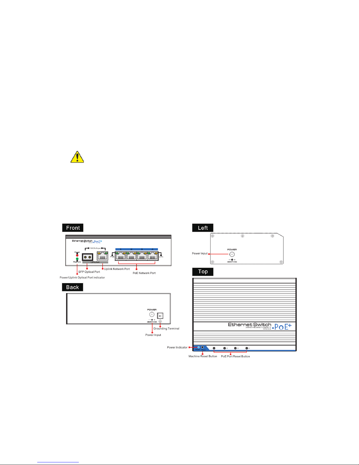
Front board with 4 PoE Ethernet ports, the yellow light on the RJ 45 socket
left side is to indicate the PoE status, the green light on the right side is to
indicate network status. There are 2 Uplink ports,1 SFP Optical port (reserva-
tion, congure optical transceiver depend on the customer's requirement)
and 1 Ethernet port. The green LED on the leftside is to indicate optical port
working status, red LED is to indicate power status, the green light on the
Ethernet RJ 45 socket is to indicate Ethernet port working status.
Installation steps
Please check the following items before installation.
If any missing, please contact the dealer.
4 Ports POE Ethernet switch 1pc
MIT hangers 2pcs
Din rail hanger 1pc
User manual 1pc
Please follow the following installation steps
1) Please turn o the signal source and the device's power, installation with
power on may damage the device;
2) Use 4 network cables to connect 4 IP cameras with POE switch's1~4PoE
port.
3) Use another network cable (or optical ber) to connect PoE Ethernet
switch's UPLINK port with NVR or computer.
4) Connect PoE switch with power adapter;
5) Check if the installation is correct and device is good, make sure all the
connection is reliable and power up the system.
6) Make sure every network device has power supply and work normally

LTV-S7204E-PoE Switch
This switch provides a uplink Ethernet port and one 100Mbps optical port;
four 100Mbps PoE Ethernet ports support IEEE802.3af/at standard. This
product is designed for HD IP Cameras. It makes the connection of those
devices far away from the power more exible and simplies wiring. This
product contains a optical port to realize perfect integration between ber
optical transceiver and Ethernet switch and by this solves the problem of
long distance transmission.
Features
Four 10/100Mbps PoE Ethernet ports, support power supply for the net-
work device meet IEEE802.3 af/at standard.
PoE network port support IEEE802.3 af/at standard, it can provide 30W
consumption and power supply to the big consumption infrared camera.
If provides 2 uplink ports, 100Mbps optical port and Ethernet port. Uplink
optical port reserve SFP port for users to select dierent performance SFP
optical ber module, conveniently solving the problem of long distance
transmission.
The switch and every PoE Ethernet port does have a reset button for users
to solve IP camera crash and others problems. No need to pullout and plug
network cables. The reset button is on the bevel.

Protection
Communication Port 4KV per: IEC61000-4-5
ESD
1a contact discharge 3 level
1b air discharge 3 level
Per: IEC61000-4-2
Environmental
Working temperature -40°C-75°C
Storage temperature -40°C-75°C
Humidity (non-conden-
sing) 0-95%
Mechanical
Dimension (L×W×H) 159mm×110mm×46.5mm
Material Aluminum
Color Black
Weight 540g
Stability MTBF >200000h
Product are subject to change without prior notice.
Trouble Shooting
Please nd the following solution when the device doesn't work
Please conrm if the installation is correct.
Please conrm if the RJ45 cable order in accordance with the EIA/TIA568A
or 568B industry standards.
The maximum consumption of every PoE port can supply to the PoE device
can't over 30 W, please do not use the PoE device which consumption over
30W.
Please replace a normal device with a failure one to check if the device is
broken.
If the problem still exist, please contact your local dealer.

Notice
When choose RJ-45 make sure if one end is EIA/TIA568A,the other end
should also be EIA/TIA568A.
When choose RJ-45 make sure if one end is EIA/TIA568B,the other end
should also be EIA/TIA568B.
RJ 45 Making Method
Instruments to be used: wire crimper, network tester. Wire sequence of RJ45
plug should conform with EIA/TIA568A or 568B.
1) Shuck o about 2cm long the insulating layer, and bar the 4 pairs UTP
cable.
2) Depart the 4 pairs UTP cable and straighten them.
3) Line up the 8 pieces of cables per EIA/TIA 568A or 568B.
4) Cut out 1.5 cm cable wrap and leave the bare wire.
5) Plug 8 cables into RJ45 plug, make sure each cable is in each pin.
6) Then use wire crimper to crimp it.
7) Follow the 5 steps above to make the another end, following the same
sequence of the rst plug.

Support IEEE802.3X full duplex ow control; support Auto MDI/MDIX functi-
on. The transmission distance of uplink Ethernet port up to 150m.
Redundance power design, power heat backup or raise power consump-
tion. Industrial standard product, fold metal outershell heat dissipation
without fan designed.
Excellent circuit isolation protection, the lightning protection can up to 4KV;
Installation fast, easily operation, convenient for wall, din rail and desktop
installation.
Notice
1) Transmission distance is related to the connecting cable. We suggest to
use standard Cat5e/6 network cable to get the 150m transmission distance.
2) If using optical port, customer need to purchase SFP module additional.
Board diagram

Specication
Item Description
Power
Power Supply Power Adapter 48V 1.25A
Voltage Range DC 48V-57V
Power Consumption <5W
Network
Connector
Network Port
1-4 port:10/100Mbps PoE
network port
UPLINK port:10/100Mbps
network port
SFP:100Mbps optical ber SFP
module port
Transmission Distance
UPLINK port:0~ 150m
SFP: Depend on the optical module
transmission performance
Transmission Medium Cat5e/6 Standard Network Cable
PoE Protocol IEEE802.3af/at
PoE Power Supply End span
PoE Power Consumption Every PoE port output <30W;
Network
Switch
Network Standard
IEEE802.3 10BASE-T, IEEE802.3u
100BASE-TX, IEEE802.3ab 1000BA-
SE-TX; IEEE802.3z 1000-SX/LX;
IEEE802.3 X
Switch Way Store and forward
Package Data Cache 512K
MAC address list 2K
LED Status
Indicators
Power 1 (red) on the front board; 1(red) on
the lean board
Optical Port 1 SFP port indicator (green)
Uplink Network Port 1 (green on the RJ 45 socket)
PoE Network
4 PoE status indicator (yellow on the
RJ 45 socket)
4 network status indicator (green)
Button
PoE Reset Button 4 corresponding with 1-4 port, PoE
reset after press the button
Reset button 1, switch restart after press this
button

LTV Europe Sicherheitstechnik GmbH
Am Wall 113
28195 Bremen
www.ltv-cctv.eu
support@ltv-cctv.eu
The LTV Europe Sicherheitstechnik GmbH as the publisher of this document, provi-
des no warranties related to the accuracy, completeness and topicality of the cont-
ent. The LTV Europe Sicherheitstechnik GmbH furthermore reserves the right to pub-
lish updated and revised versions of this document without prior notice. The names,
tradenames, trademarks etc. described in this work are used without guarantee of
free usability, and may be registered trademarks or brands without specic labelling,
and as such may be subject to legal regulations. This work is protected by copyright.
All rights, including the right to reproduce, reprint and the distribution and transla-
tion of this document, or parts thereof, are reserved. No part of this document may
be in any way reproduced, or electronically stored, processed, copied or distributed,
without written permission of the publisher or author, not even for the purpose of
teaching. All rights reserved.
© 2015 Version 01/2015
Table of contents
Other LTV Network Router manuals
Popular Network Router manuals by other brands

Cabletron Systems
Cabletron Systems Spectrum EMM-E6 installation guide

LevelOne
LevelOne FBR-1403TX user guide

ZyXEL Communications
ZyXEL Communications Prestige 650HW user guide

HP
HP a-msr Configuration guide

HARTING
HARTING Ha-VIS FTS 3100s-A Installation notes for electrical personnel

Digi
Digi TX54 user guide